Downloaded 239 times

![22 | P a g e BLUETOOTH BASED HOME AUTOMATION SYSTEM
Institute of Tech. & Science Indore
using 6volt relay. Many relay use an electromagnet to mechanically operate a
switch.
Fig.10. .Relays
2.5 Connector:-
Connectors are used for joining two wires temporally by using connector big
circuit can be divided and after completion they can rejoin. Now a day’s every
time inverter circuited can be removed out without using de soldering.
2.6 Aurdino burner:-
Arduino is common term for a software company, project, and user community,
that designs and manufactures computer open-source hardware, open-source
software, and microcontroller-based kits for building digital devices and
interactive objects that can sense and control physical devices.[1]](https://image.slidesharecdn.com/bluetoothbasedhomeautomationsystem-170327102946/75/Bluetooth-based-home-automation-system-22-2048.jpg)
![23 | P a g e BLUETOOTH BASED HOME AUTOMATION SYSTEM
Institute of Tech. & Science Indore
Arduino is common term for a software company, project, and user community,
that designs and manufactures computer open-source hardware, open-source
software, and microcontroller-based kits for building digital devices and
interactive objects that can sense and control physical devices.[1]
The project is based on microcontroller board designs, produced by several
vendors, using various microcontrollers. These systems provide sets of digital and
analog I/O pins that can interface to various expansion boards (termed shields)
and other circuits. The boards feature serial communication interfaces, including
Universal Serial Bus (USB) on some models, for loading programs from personal
computers. For programming the microcontrollers, the Arduino project provides
an integrated development environment(IDE) based on a programming language
named Processing, which also supports the languages C and C++.](https://image.slidesharecdn.com/bluetoothbasedhomeautomationsystem-170327102946/75/Bluetooth-based-home-automation-system-23-2048.jpg)
![24 | P a g e BLUETOOTH BASED HOME AUTOMATION SYSTEM
Institute of Tech. & Science Indore
The first Arduino was introduced in 2005, aiming to provide a low cost, easy way
for novices and professionals to create devices that interact with their
environment using sensors and actuators. Common examples of such devices
intended for beginner hobbyists include simple robots, thermostats, and motion
detectors.
Arduino boards are available commercially in preassembled form, or as do-it-
yourself kits. The hardware design specifications are openly available, allowing
the Arduino boards to be produced by anyone. Adafruit Industries estimated in
mid-2011 that over 300,000 official Arduinos had been commercially
produced,[2] and in 2013 that 700,000 official boards were in users' hands.
The project is based on microcontroller board designs, produced by several
vendors, using various microcontrollers. These systems provide sets of digital and
analog I/O pins that can interface to various expansion boards (termed shields)
and other circuits. The boards feature serial communication interfaces, including
Universal Serial Bus (USB) on some models, for loading programs from personal
computers. For programming the microcontrollers, the Arduino project provides
an integrated development environment(IDE) based on a programming language
named Processing, which also supports the languages C and C++.
The first Arduino was introduced in 2005, aiming to provide a low cost, easy way
for novices and professionals to create devices that interact with their
environment using sensors and actuators. Common examples of such devices
intended for beginner hobbyists include simple robots, thermostats, and motion
detectors.](https://image.slidesharecdn.com/bluetoothbasedhomeautomationsystem-170327102946/75/Bluetooth-based-home-automation-system-24-2048.jpg)
![25 | P a g e BLUETOOTH BASED HOME AUTOMATION SYSTEM
Institute of Tech. & Science Indore
Arduino boards are available commercially in preassembled form, or as do-it-
yourself kits. The hardware design specifications are openly available, allowing
the Arduino boards to be produced by anyone. Adafruit Industries estimated in
mid-2011 that over 300,000 official Arduinos had been commercially
produced,[2] and in 2013 that 700,000 official boards were in users' hands.
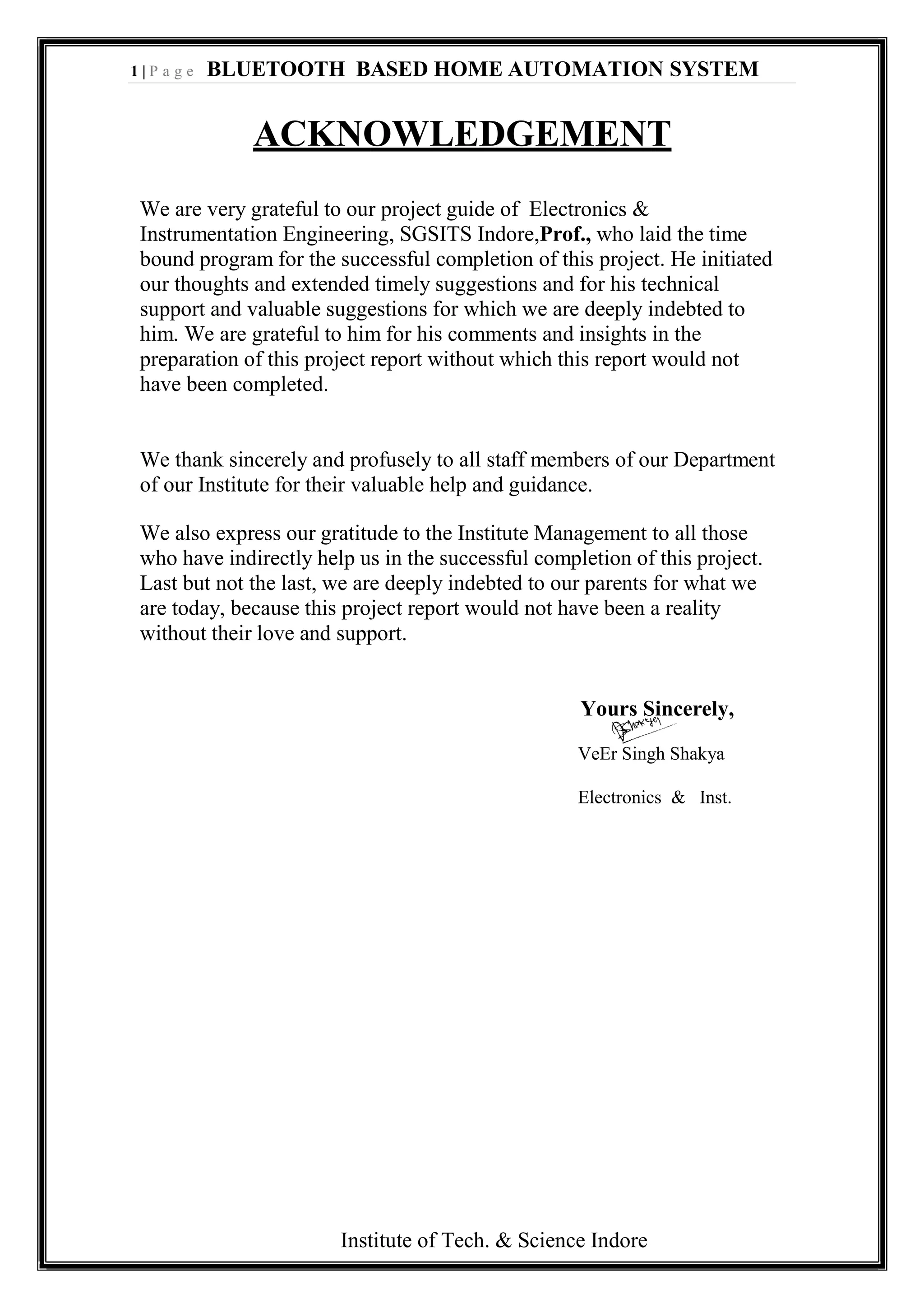
2.7 LCD:-
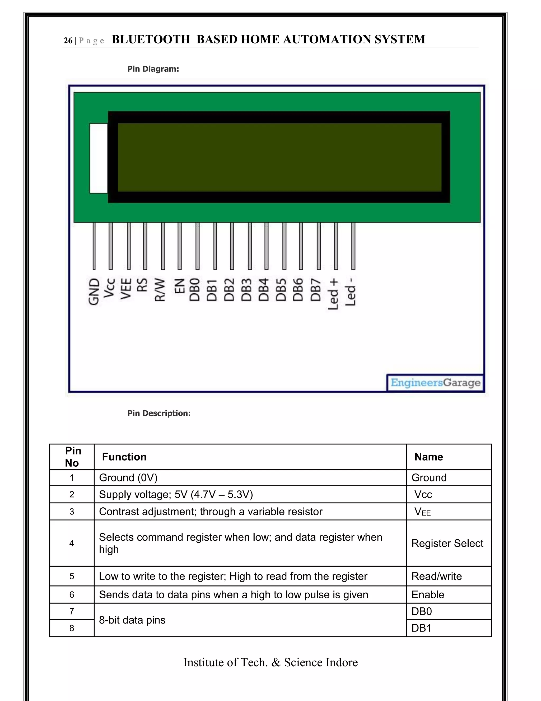
LCD (Liquid Crystal Display) screen is an electronic display module and find a wide
range of applications. A 16x2 LCD display is very basic module and is very
commonly used in various devices and circuits. These modules are preferred
over seven segments and other multi segment LEDs. The reasons being: LCDs are
economical; easily programmable; have no limitation of displaying special &
even custom characters (unlike in seven segments), animations and so on.
A 16x2 LCD means it can display 16 characters per line and there are 2 such lines.
In this LCD each character is displayed in 5x7 pixel matrix. This LCD has two
registers, namely, Command and Data.
The command register stores the command instructions given to the LCD. A
command is an instruction given to LCD to do a predefined task like initializing it,
clearing its screen, setting the cursor position, controlling display etc. The data
register stores the data to be displayed on the LCD. The data is the ASCII value of
the character to be displayed on the LCD. Click to learn more about internal
structure of a LCD.](https://image.slidesharecdn.com/bluetoothbasedhomeautomationsystem-170327102946/75/Bluetooth-based-home-automation-system-25-2048.jpg)
![27 | P a g e BLUETOOTH BASED HOME AUTOMATION SYSTEM
Institute of Tech. & Science Indore
9 DB2
10 DB3
11 DB4
12 DB5
13 DB6
14 DB7
15 Backlight VCC (5V) Led+
16 Backlight Ground (0V) Led-
3. Software
INTRODUCTION: Electronic design automation (EDA or ECAD) is a category
of software tools for designing electronic systems such as printed circuit boards
and integrated circuits. The tools work together in a design flow that chip
designers use to design and analyze entire semiconductor chips. The various
software’s used are:
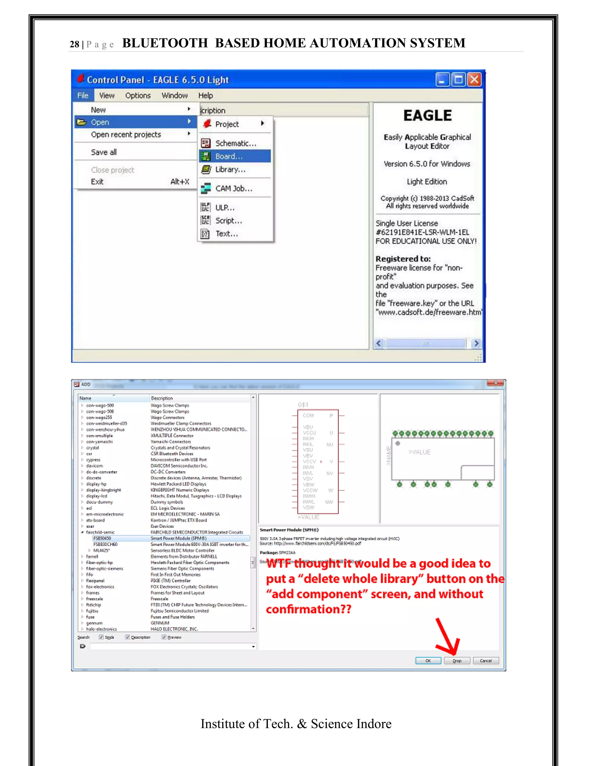
3.1 EAGLE:-
EAGLE stands for, Easily Applicable Graphical Layout Editor in English
and, Einfach anzuwendender grafischer Layout-Editor inGerman. It is designed
and developed by CadSoft Computer GmbH and is a flexible, expandable and
scriptable, electronic design automation (EDA) application with schematic capture
editor, printed circuit board (PCB) layout editor, auto-router and computer-aided
manufacturing (CAM) and bill of materials (BOM) tools. Premier Farnell bought
EAGLE in 2008.[1]](https://image.slidesharecdn.com/bluetoothbasedhomeautomationsystem-170327102946/75/Bluetooth-based-home-automation-system-27-2048.jpg)
![30 | P a g e BLUETOOTH BASED HOME AUTOMATION SYSTEM
Institute of Tech. & Science Indore
void com3();
void com2();
void com1();
void delay(const unsigned int ms);
unsigned char z;
unsigned char Mess1[]="SW OFF,";
unsigned char Mess2[]="SW ONN,";
unsigned char Mess3[]="Access Denied,";
void main()
{
unsigned char mybyte;
unsigned char old;
unsigned char rx;
TMOD=0x20; //use Timer 1, mode 2
TH1=0xFD; //9600 baud rate
SCON=0x50;
TR1=1; //start timer
while (1) { //repeat forever
while (RI==0); //wait to receive; //save value](https://image.slidesharecdn.com/bluetoothbasedhomeautomationsystem-170327102946/75/Bluetooth-based-home-automation-system-30-2048.jpg)
![36 | P a g e BLUETOOTH BASED HOME AUTOMATION SYSTEM
Institute of Tech. & Science Indore
SBUF=Mess3[z]; //place value in buffer
while(TI==0); //wait for transmit
TI=0;
}
}
void com2()
{
for (z=0;z<8;z++) {
SBUF=Mess2[z]; //place value in buffer
while(TI==0); //wait for transmit
TI=0;
}
}
void com1()
{
for (z=0;z<8;z++) {](https://image.slidesharecdn.com/bluetoothbasedhomeautomationsystem-170327102946/75/Bluetooth-based-home-automation-system-36-2048.jpg)
![37 | P a g e BLUETOOTH BASED HOME AUTOMATION SYSTEM
Institute of Tech. & Science Indore
SBUF=Mess1[z]; //place value in buffer
while(TI==0); //wait for transmit
TI=0;
}
}
void delay(const unsigned int ms)
{
unsigned int x, y;
for(x = 0; x<=ms;x++)
{
for(y=0;y<=1275;y++);
}
}
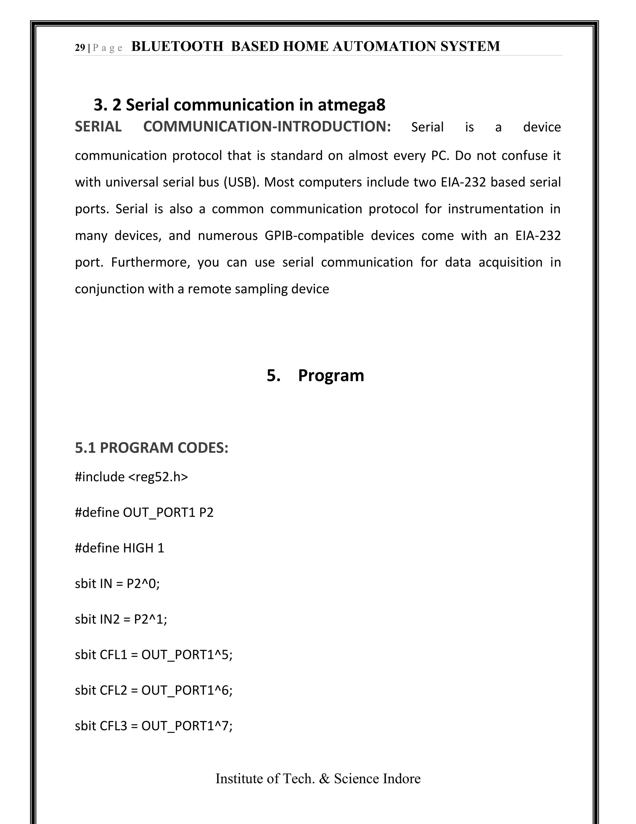
5.2 Program detail
1. #include <reg52.h>:-By using this we define the header file of micro –
controller 89s52.
2. #define OUT_PORT2 P1:-this line is used for defining a port with output
port.](https://image.slidesharecdn.com/bluetoothbasedhomeautomationsystem-170327102946/75/Bluetooth-based-home-automation-system-37-2048.jpg)

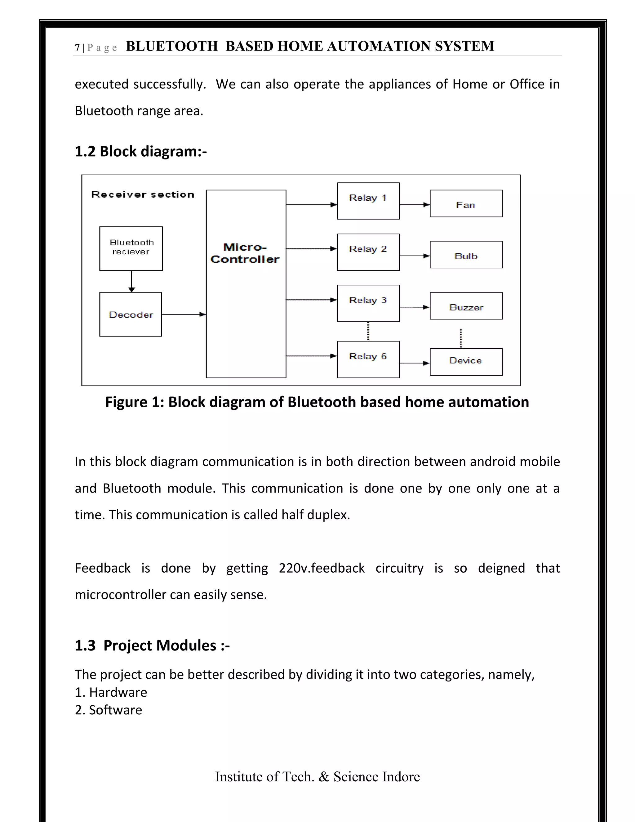
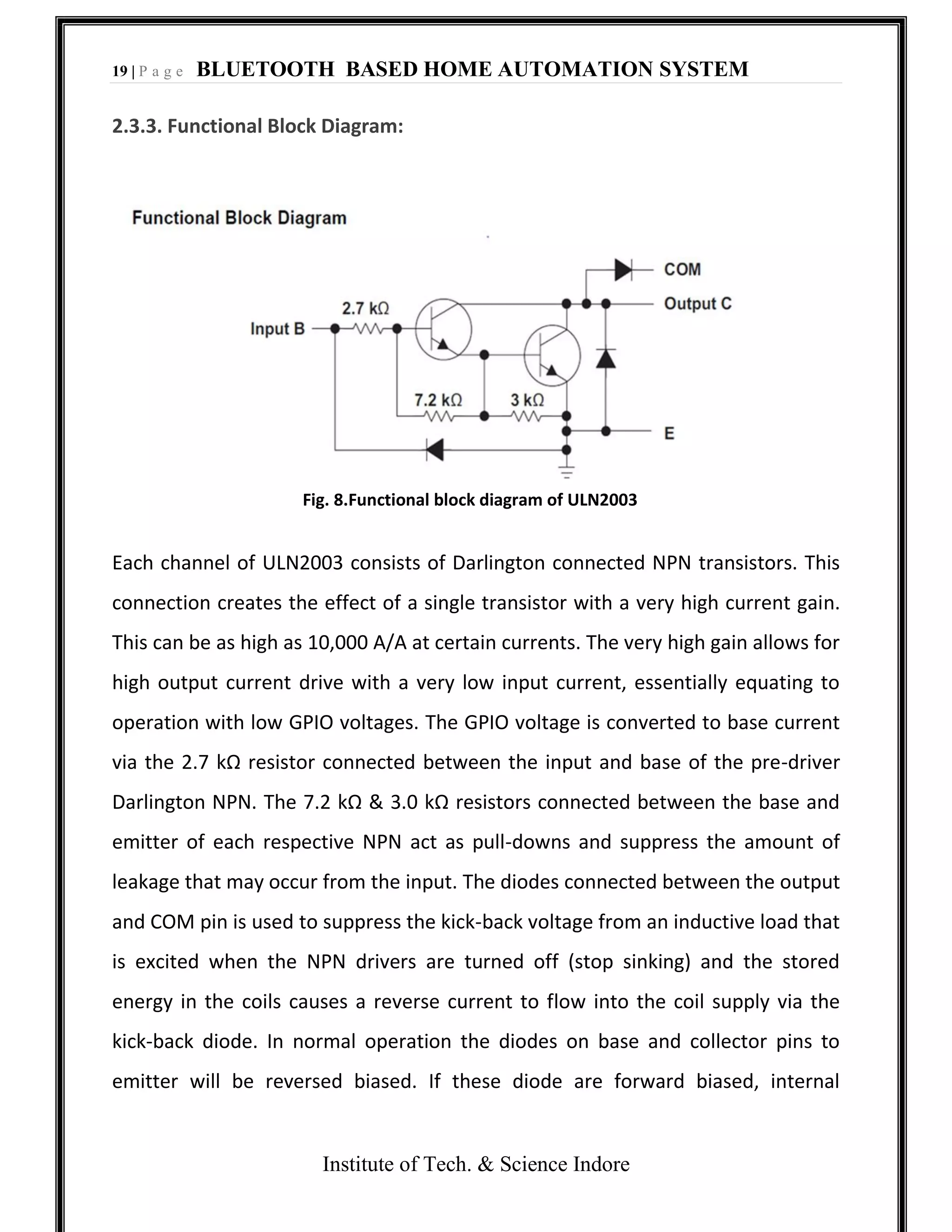
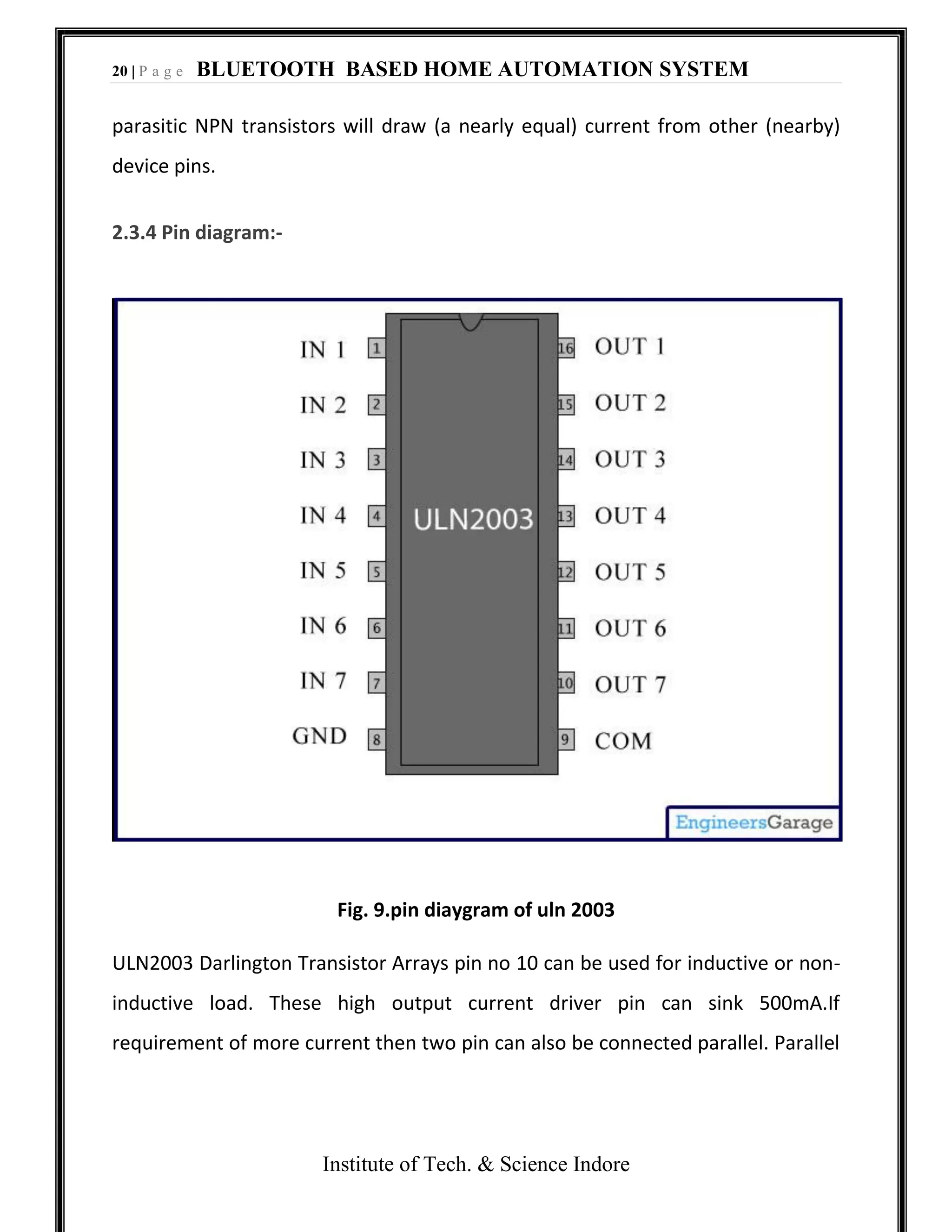
The document provides an overview of a Bluetooth based home automation system project. It includes a block diagram of the system which uses an ATmega8 microcontroller and HC-05 Bluetooth module to allow wireless control of home appliances like lights and fans from an Android mobile phone. The hardware and software components are described, including the microcontroller, Bluetooth module, driver IC, switches, power supply. It also discusses the serial communication between the microcontroller and Bluetooth module for transmitting commands from the phone to control the appliances.