Downloaded 113 times


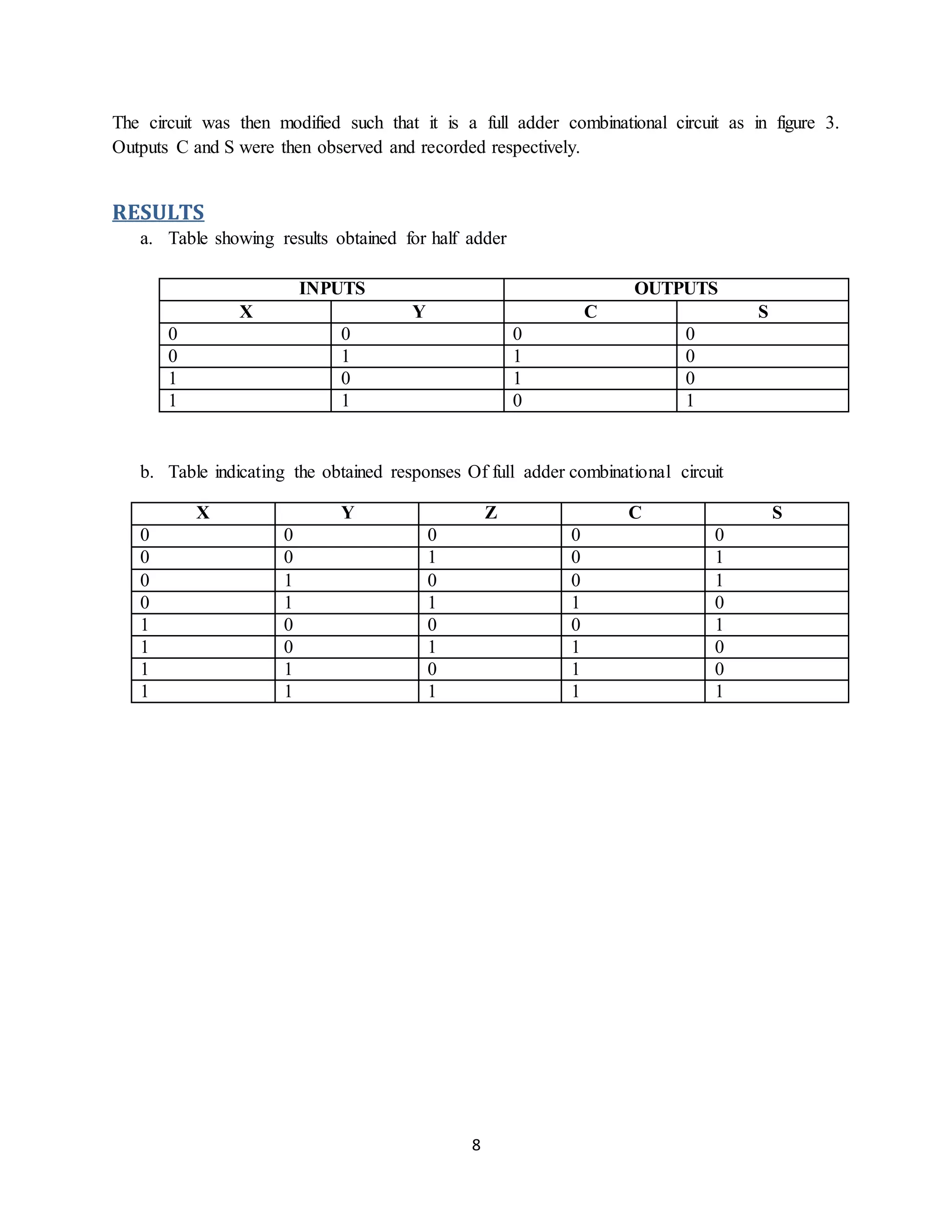


This document describes a laboratory experiment on logic gates and combinational circuits conducted by students at the University of Botswana. The aim was to introduce half adders and full adders. Students used AND, OR, and XOR gates to build the circuits on a breadboard. Their results matched the theoretical truth tables. Issues arose due to crowded workspaces and old equipment. Recommendations included upgrading equipment and better preparation by students. The conclusion was that practical observations matched expectations, demonstrating an understanding of combinational circuit design.