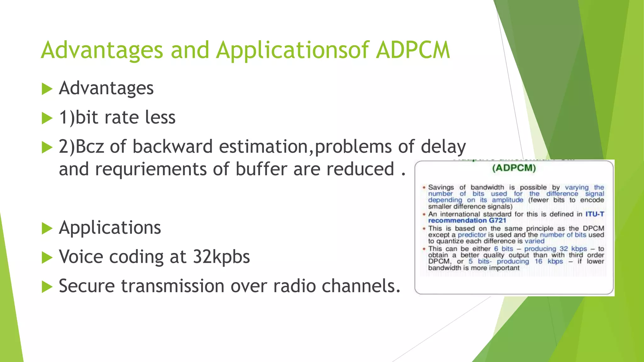
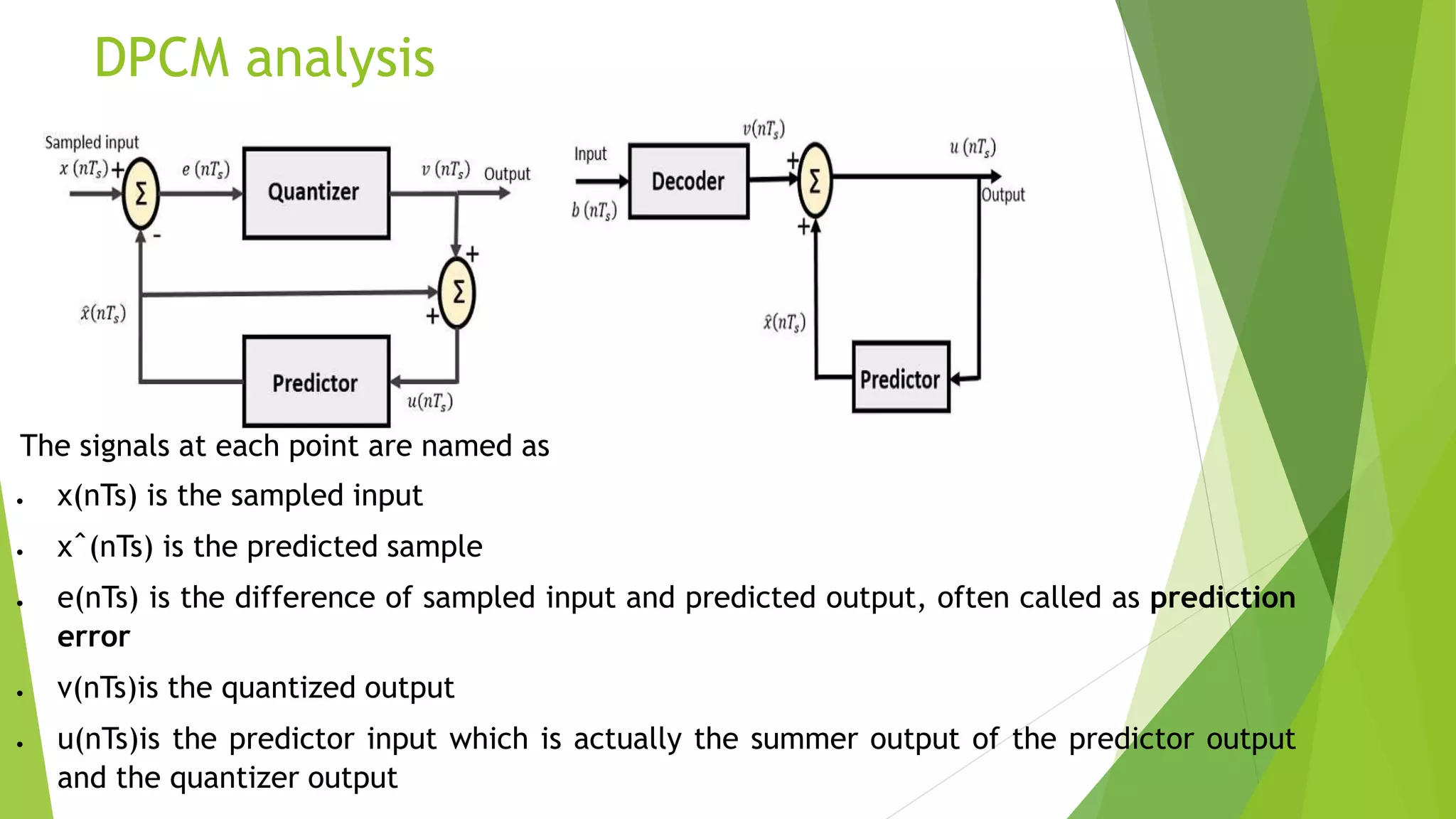
DPCM
Differential Pulse code
Modulation
By K.Ramya Sree
18BF1A0485
ECE – B
Sri Venkateswara College Of Engineering,Tirupati.
Why we need DPCM?
Short Review of PCM
 Short review of PCM
For the samples that are
highly correlated,when
encoded by PCM,will
leave Redundant
information behind.
Cause for Redundancy
●High Correlation b/w
conjugation bits.
●When sampled at a rate
slightly greater that Nyquist
rate.(fs>2W)
Where W is maximum
frequency of the analog i/p
signal.
Redundant bits
means Extra bits.
What is high correlation?
High correlation with reference to
DPCM.
 During the process of quantization
the signal doesnot change rapidly from one samples to the next sample.
With the result that the difference b/w adjacent samples has variance that is
smaller than the variance of the signal itself.
I.e;variance (difference b/w adjacent sample) < variance (digitalized signal)
So at this case the samples obtained are called as highly correlated samples.
Redundant Information bits in PCM
Signal x(t) sampled by flat top sampling.
 The above figure shows a continuing time signal x(t) denoted by a dotted line.
 This signal is sampled by flat-top sampling at intervals Ts, 2Ts, 3Ts…nTs.
 The sampling frequency is selected to be higher than the Nyquist rate.
 These samples are encoded by using 3-bit (7 levels) PCM.
 The samples are quantized to the nearest digital level as shown by small circles
in the above figure.
 The encoded binary value of each sample is written on the top of the samples.
Just observe the above figure at samples taken at 4Ts, 5Ts, and 6Ts are
encoded to the same value of (110). This information can be carried only by one
sample value. But three samples are carrying the same information means
redundant.
 Now let consider the samples at 9Ts and 10Ts, the difference between these
samples only due to the last bit and first two bits are redundant since they do not
change.
How to process the
Redundant Information?
Solution
 DPCM(differential pulse code modulation)
 To process this Redundant Information and to
have better output,it is a wise decision to take
the predicted sampled values ,assumed from its
previous output and summarize them with the
original quantised values.And such process is
called as DPCM.
 DPCM is a derivative of standard PCM.
 Differential pulse code modulation (DPCM) is a
procedure of converting an analog into a digital signal
in which an analog signal is sampled and then the
difference between the actual sample value and its
predicted value (predicted value is based on previous
sample or samples) is quantized and then encoded
forming a digital value.
 DPCM Reduces the bit rate.
 DPCM code words represent differences between
samples unlike PCM where code words represented a
sample value.
DPCM analysis
The signals at each point are named as −
 x(nTs) is the sampled input
 xˆ(nTs) is the predicted sample
 e(nTs) is the difference of sampled input and predicted output, often called as prediction
error
 v(nTs)is the quantized output
 u(nTs)is the predictor input which is actually the summer output of the predictor output
and the quantizer output
Quantizer Output is represented as −
v(nTs)=Q[e(nTs)]
=e(nTs)+q(nTs)
v(nTs)= e(nTs)+q(nTs) eqn 1
Where q (nTs) is the quantization error
Predictor input
u(nTs)=xˆ(nTs)+v(nTs)  eqn 2
u(nTs)=xˆ(nTs)+e(nTs)+q(nTs) (from eqn 1)
predictor output quantizer output
Result :Predictor input is the sum of
quantizer output and predictor output,
The same predictor circuit is used in the
decoder to reconstruct the original input.
DPCM Reciever The block diagram of DPCM
Receiver consists of
a decoder
a predictor
a summer circuit
The input given to the decoder is
processed and that output is summed up with
the output of the predictor, to obtain a better
output.
In the absence of noise, the encoded
receiver input will be the same as the
encoded transmitter output.
Prediction gain
Variance of message signal assumed to
be zero mean.
Variance of prediction error
Variance of
quantization
error
ADPM
 Adaptive differential pulse-code modulation (ADPCM) is a variant
of differential pulse-code modulation (DPCM) that varies the size of the
quantization step,(variation of step size depends upon amplitude levels)
 to allow further reduction of the required data bandwidth for a given signal-to-
noise ratio.
 Also reduces the bit rate.
 ADPCM implemented using forward
Logic for
adaptive
prediction
Or backward estimation.
In forward estimation,unquantized
sample of i/p signal is used to obtain
the step size.
in backward estimation,quantizer
o/p samples are used to obtain step
size.
Advantages and Applicationsof ADPCM
 Advantages
 1)bit rate less
 2)Bcz of backward estimation,problems of delay
and requriements of buffer are reduced .
 Applications
 Voice coding at 32kpbs
 Secure transmission over radio channels.
Any Queries ??
Thankyou

Dpcm

  • 1.
    DPCM Differential Pulse code Modulation ByK.Ramya Sree 18BF1A0485 ECE – B Sri Venkateswara College Of Engineering,Tirupati.
  • 2.
  • 3.
    Short Review ofPCM  Short review of PCM For the samples that are highly correlated,when encoded by PCM,will leave Redundant information behind. Cause for Redundancy ●High Correlation b/w conjugation bits. ●When sampled at a rate slightly greater that Nyquist rate.(fs>2W) Where W is maximum frequency of the analog i/p signal. Redundant bits means Extra bits.
  • 4.
    What is highcorrelation?
  • 5.
    High correlation withreference to DPCM.  During the process of quantization the signal doesnot change rapidly from one samples to the next sample. With the result that the difference b/w adjacent samples has variance that is smaller than the variance of the signal itself. I.e;variance (difference b/w adjacent sample) < variance (digitalized signal) So at this case the samples obtained are called as highly correlated samples.
  • 6.
    Redundant Information bitsin PCM Signal x(t) sampled by flat top sampling.
  • 7.
     The abovefigure shows a continuing time signal x(t) denoted by a dotted line.  This signal is sampled by flat-top sampling at intervals Ts, 2Ts, 3Ts…nTs.  The sampling frequency is selected to be higher than the Nyquist rate.  These samples are encoded by using 3-bit (7 levels) PCM.  The samples are quantized to the nearest digital level as shown by small circles in the above figure.  The encoded binary value of each sample is written on the top of the samples. Just observe the above figure at samples taken at 4Ts, 5Ts, and 6Ts are encoded to the same value of (110). This information can be carried only by one sample value. But three samples are carrying the same information means redundant.  Now let consider the samples at 9Ts and 10Ts, the difference between these samples only due to the last bit and first two bits are redundant since they do not change.
  • 8.
    How to processthe Redundant Information?
  • 9.
    Solution  DPCM(differential pulsecode modulation)  To process this Redundant Information and to have better output,it is a wise decision to take the predicted sampled values ,assumed from its previous output and summarize them with the original quantised values.And such process is called as DPCM.  DPCM is a derivative of standard PCM.
  • 10.
     Differential pulsecode modulation (DPCM) is a procedure of converting an analog into a digital signal in which an analog signal is sampled and then the difference between the actual sample value and its predicted value (predicted value is based on previous sample or samples) is quantized and then encoded forming a digital value.  DPCM Reduces the bit rate.  DPCM code words represent differences between samples unlike PCM where code words represented a sample value.
  • 11.
    DPCM analysis The signalsat each point are named as −  x(nTs) is the sampled input  xˆ(nTs) is the predicted sample  e(nTs) is the difference of sampled input and predicted output, often called as prediction error  v(nTs)is the quantized output  u(nTs)is the predictor input which is actually the summer output of the predictor output and the quantizer output
  • 12.
    Quantizer Output isrepresented as − v(nTs)=Q[e(nTs)] =e(nTs)+q(nTs) v(nTs)= e(nTs)+q(nTs) eqn 1 Where q (nTs) is the quantization error Predictor input u(nTs)=xˆ(nTs)+v(nTs)  eqn 2 u(nTs)=xˆ(nTs)+e(nTs)+q(nTs) (from eqn 1) predictor output quantizer output Result :Predictor input is the sum of quantizer output and predictor output, The same predictor circuit is used in the decoder to reconstruct the original input.
  • 13.
    DPCM Reciever Theblock diagram of DPCM Receiver consists of a decoder a predictor a summer circuit The input given to the decoder is processed and that output is summed up with the output of the predictor, to obtain a better output. In the absence of noise, the encoded receiver input will be the same as the encoded transmitter output.
  • 14.
    Prediction gain Variance ofmessage signal assumed to be zero mean. Variance of prediction error Variance of quantization error
  • 15.
    ADPM  Adaptive differentialpulse-code modulation (ADPCM) is a variant of differential pulse-code modulation (DPCM) that varies the size of the quantization step,(variation of step size depends upon amplitude levels)  to allow further reduction of the required data bandwidth for a given signal-to- noise ratio.  Also reduces the bit rate.  ADPCM implemented using forward Logic for adaptive prediction Or backward estimation. In forward estimation,unquantized sample of i/p signal is used to obtain the step size. in backward estimation,quantizer o/p samples are used to obtain step size.
  • 16.
    Advantages and ApplicationsofADPCM  Advantages  1)bit rate less  2)Bcz of backward estimation,problems of delay and requriements of buffer are reduced .  Applications  Voice coding at 32kpbs  Secure transmission over radio channels.
  • 17.
  • 18.