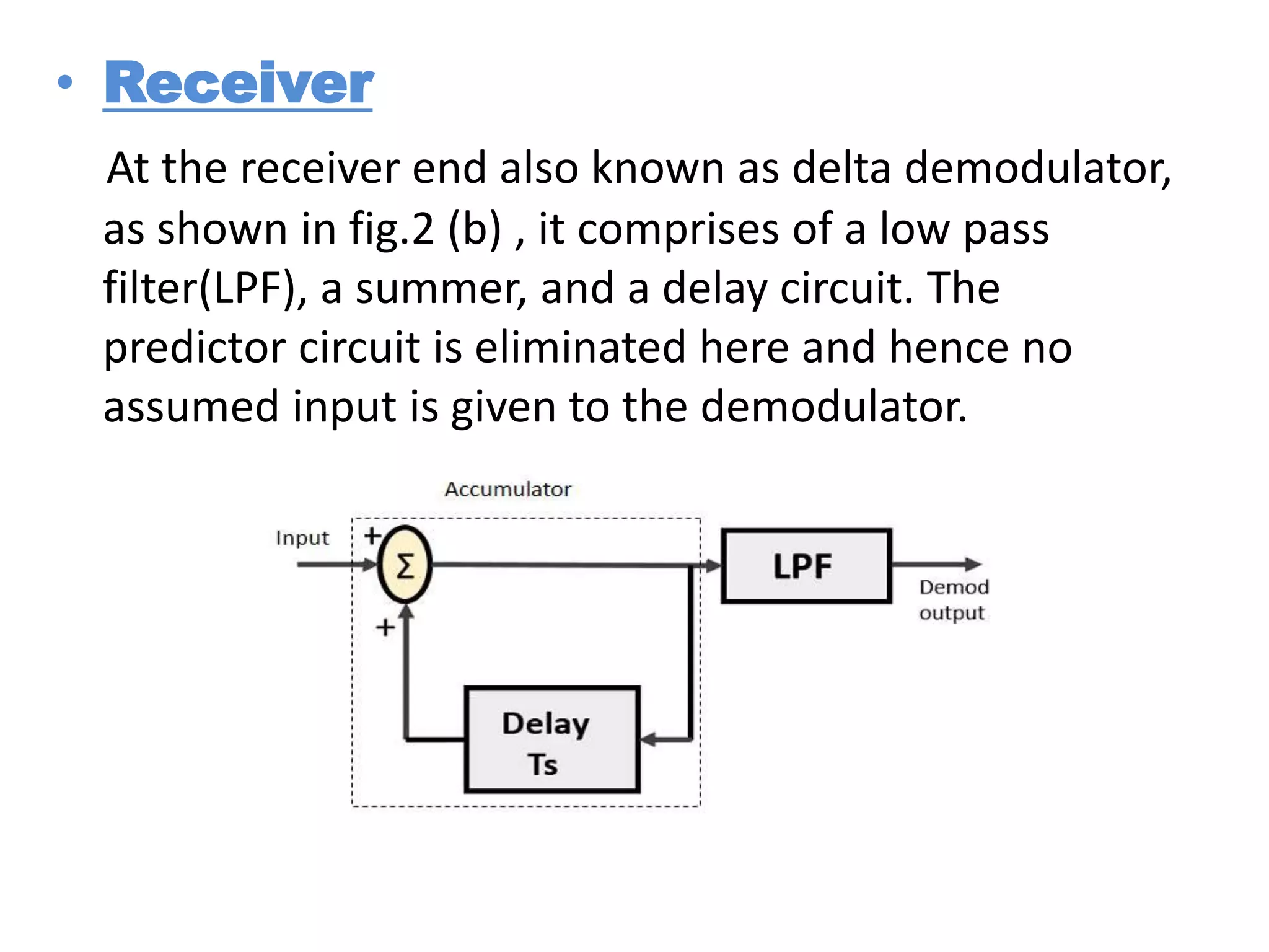
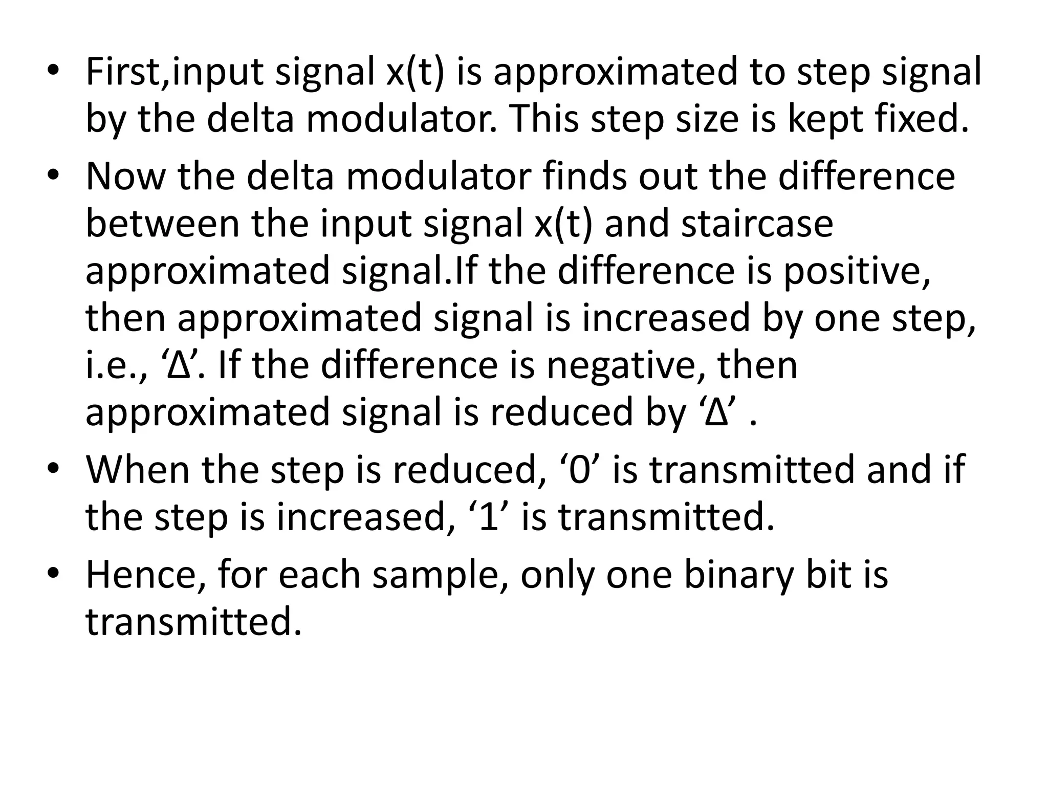
Delta modulation is a signal encoding technique used to more efficiently transmit analog signals over bandwidth-limited channels. It works by approximating the input signal as a staircase function and transmitting only a single bit per sample to indicate whether the signal increased or decreased from the previous sample. At the receiver, the bits are used to reconstruct the staircase approximation, which is then filtered to recover the original analog signal. The key aspects are transmitting only a single bit per sample, using a fixed step size, and increasing or decreasing the approximated signal based on the signal differences.

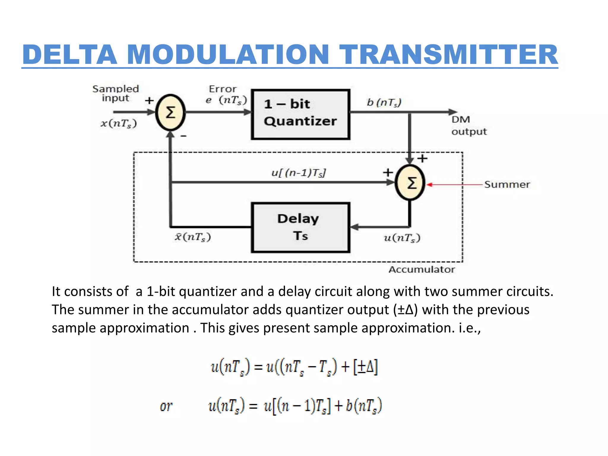
![• The previous sample approximation u[(n-1)Ts ]
is restored by delaying one sample period Ts .
• The samples input signal x(nTs ) and staircase
approximated signal xˆ(nTs ) are subtracted to
get error signal e(nTs ).
• Thus, depending on the sign of e(nTs ), one bit
quantizer generates an output of +Δ or -Δ .
• If the step size is +Δ, then binary ‘1’ is
transmitted and if it is -Δ, then binary ‘0’ is
transmitted](https://image.slidesharecdn.com/deltamodulation-200630072715/75/Delta-modulation-8-2048.jpg)