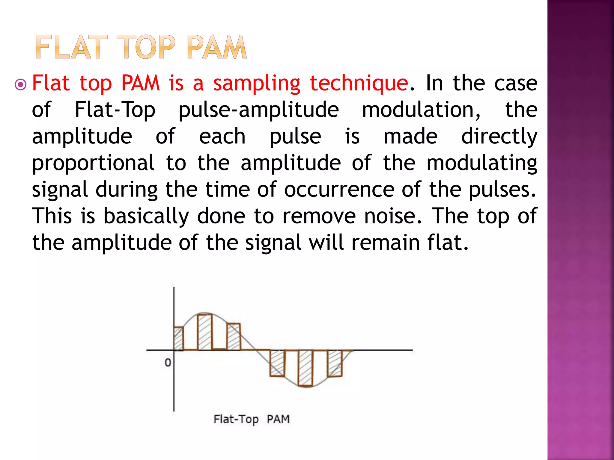
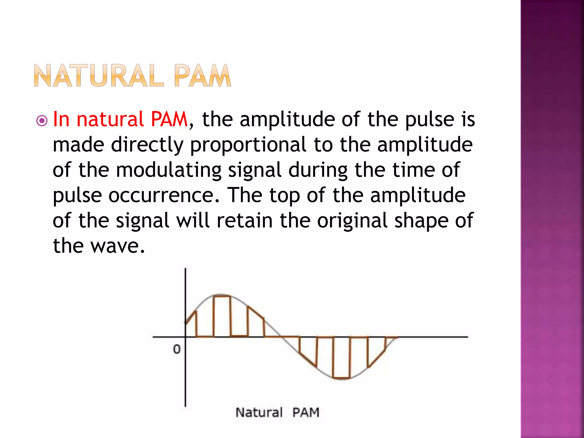
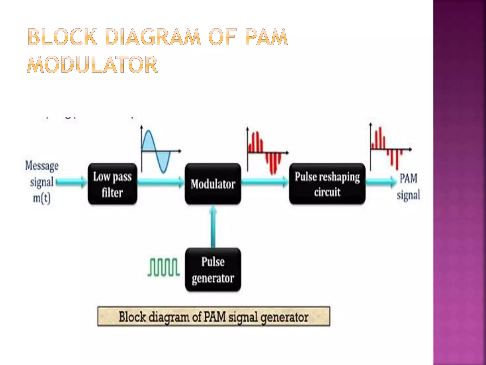
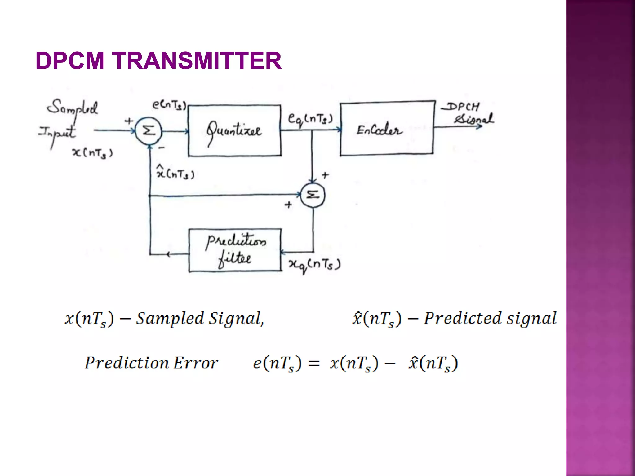
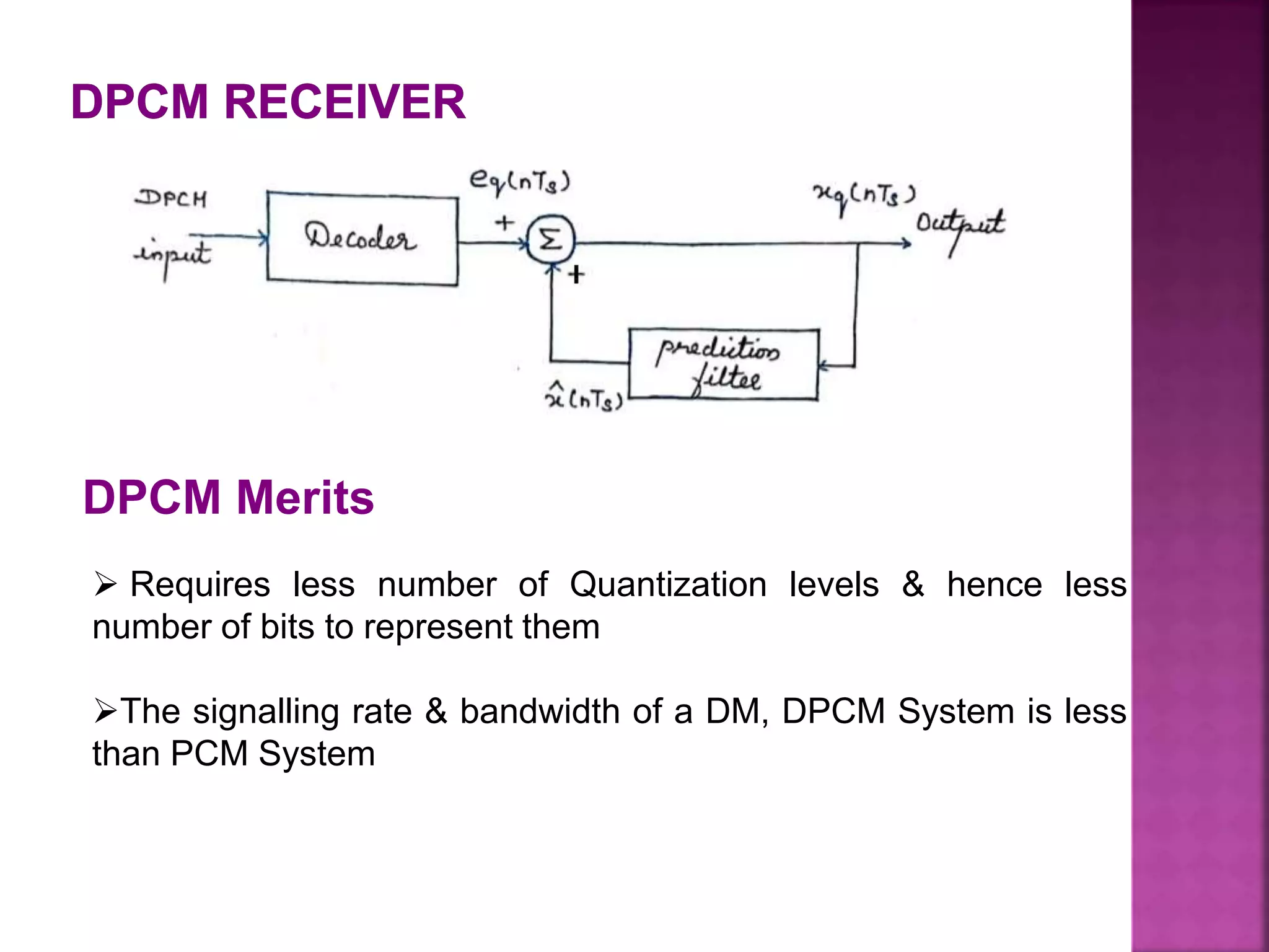
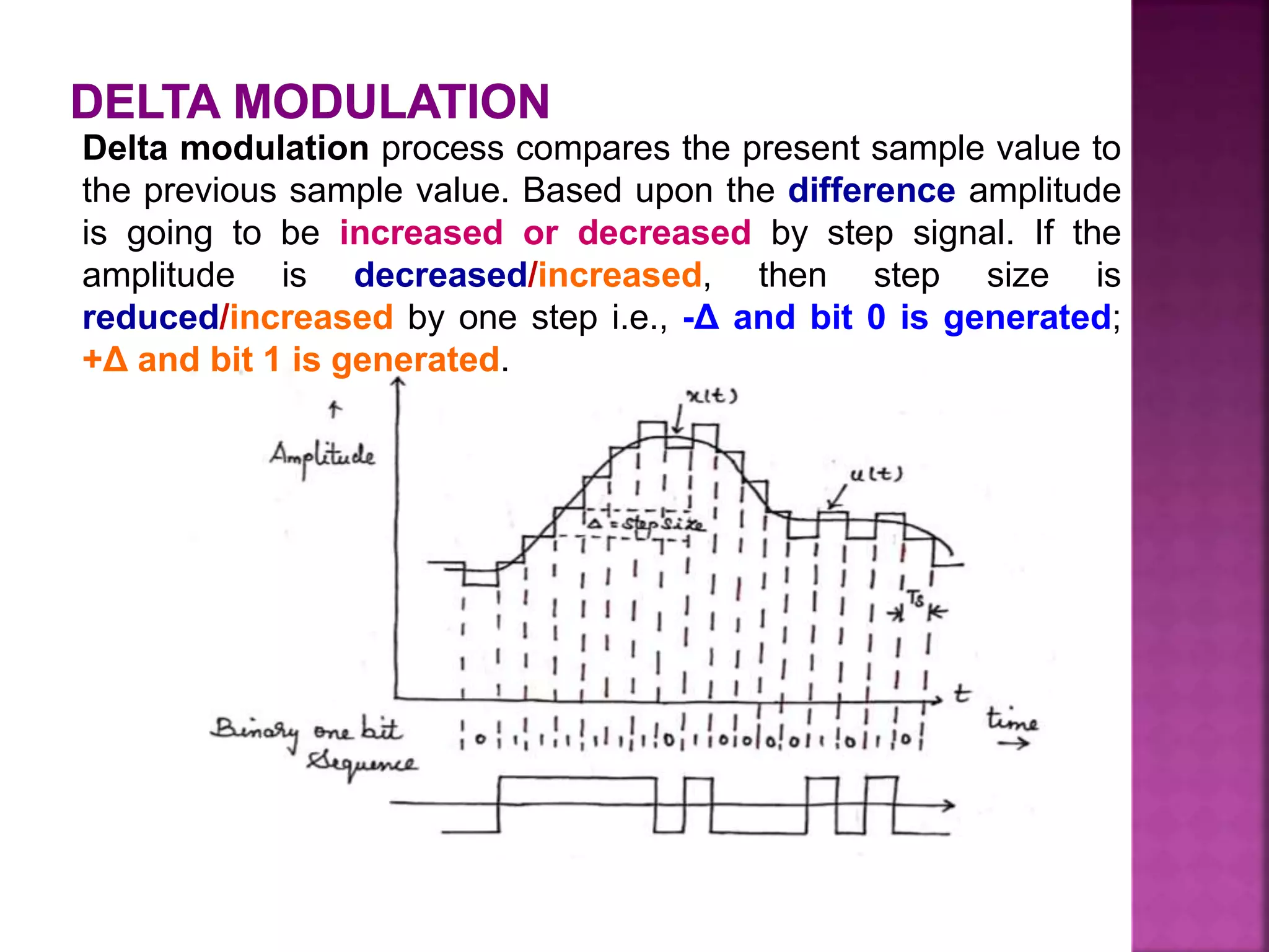
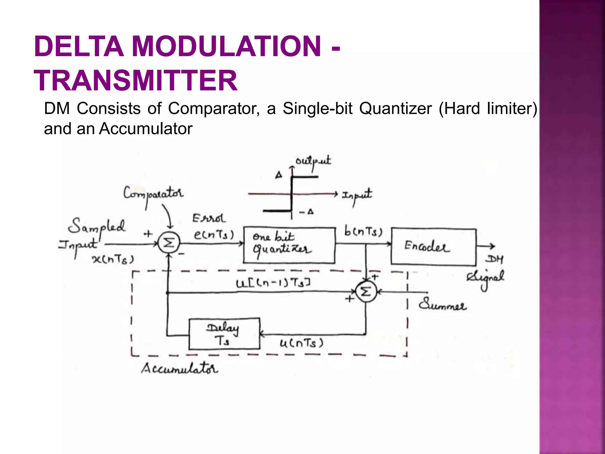
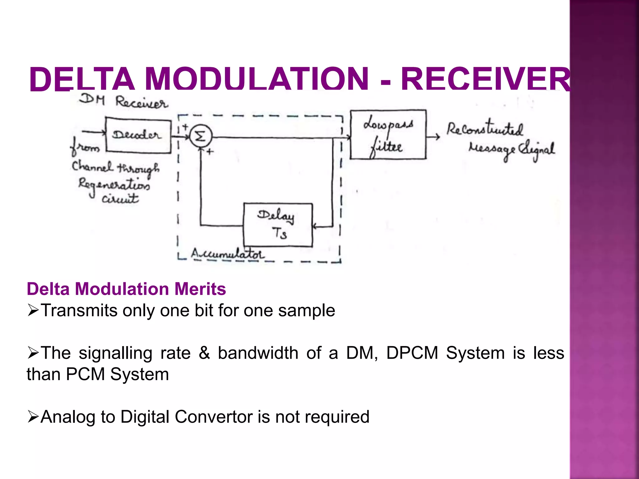
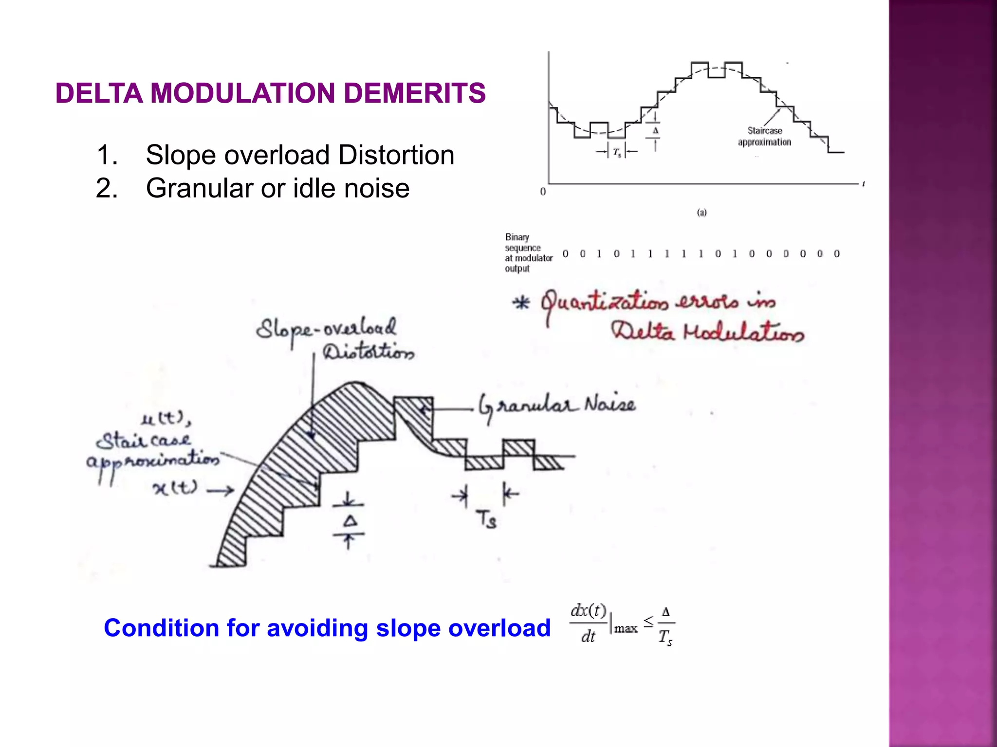
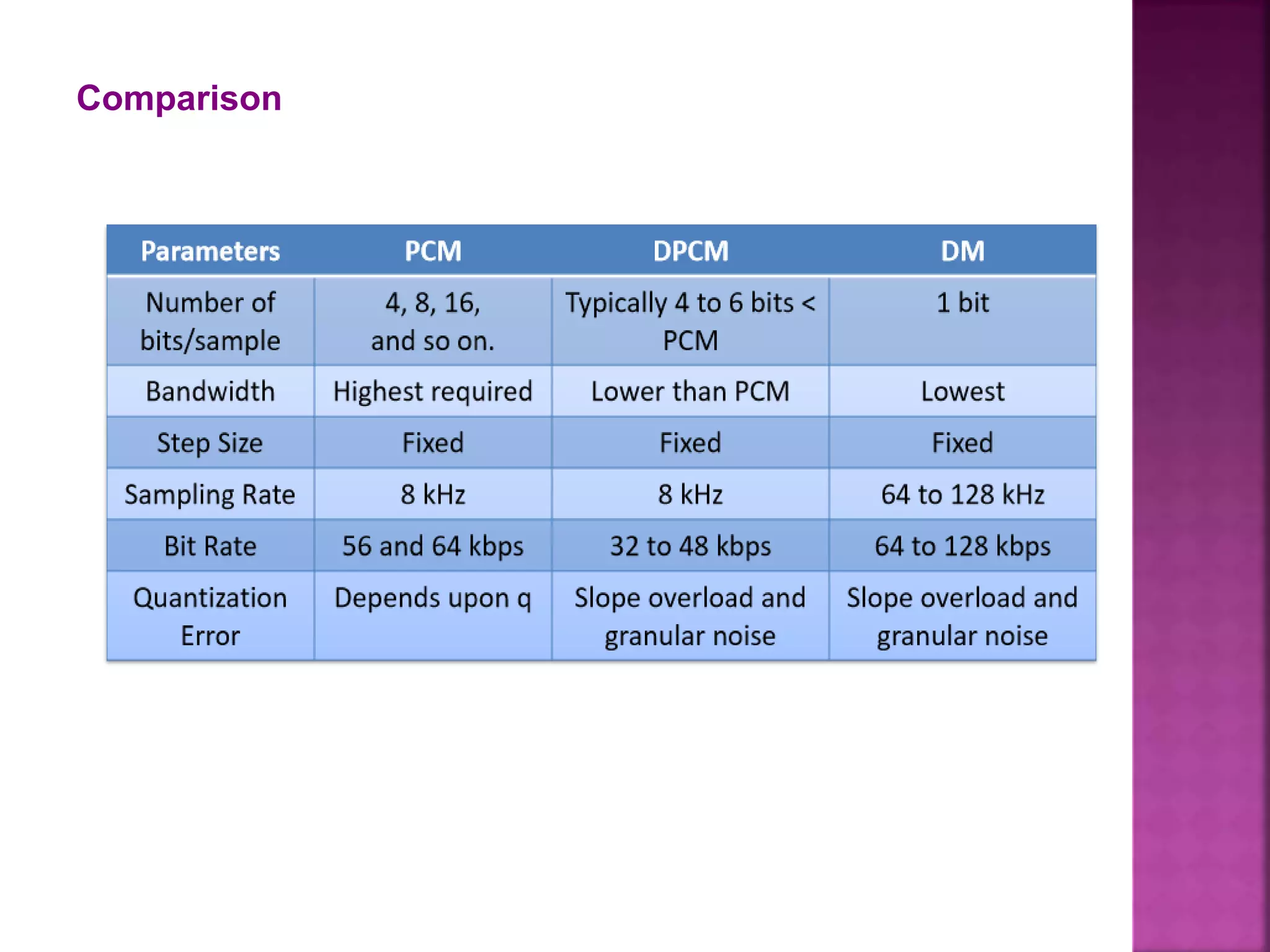
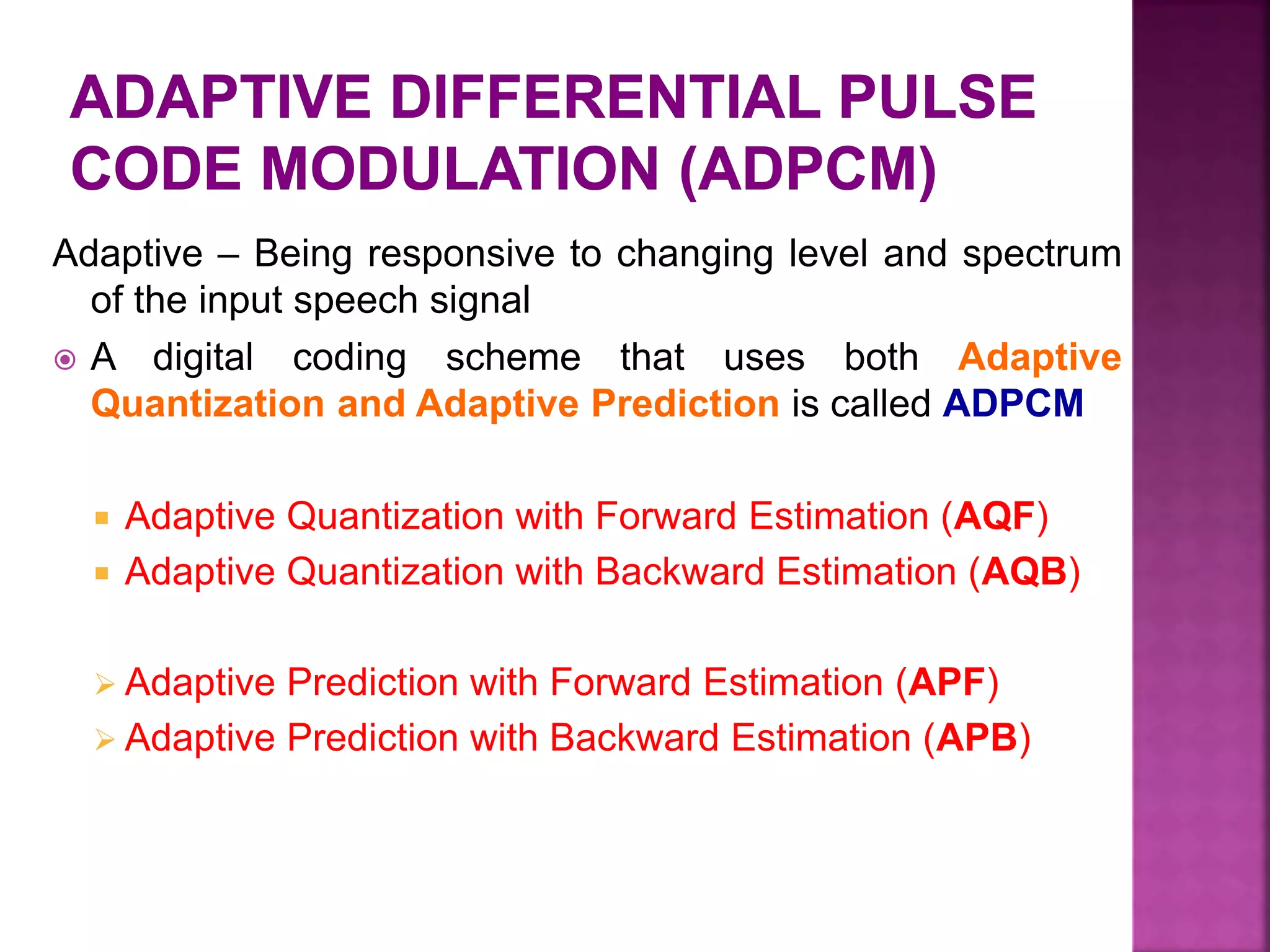
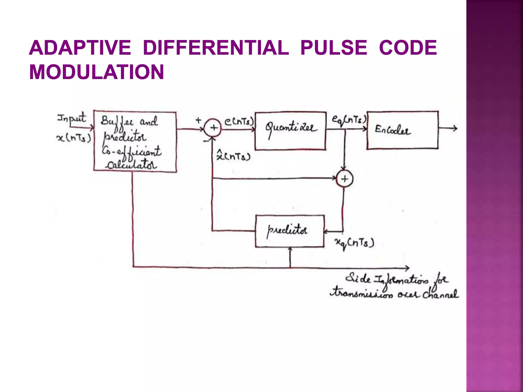
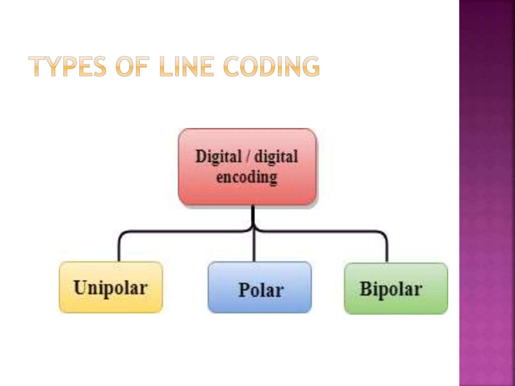
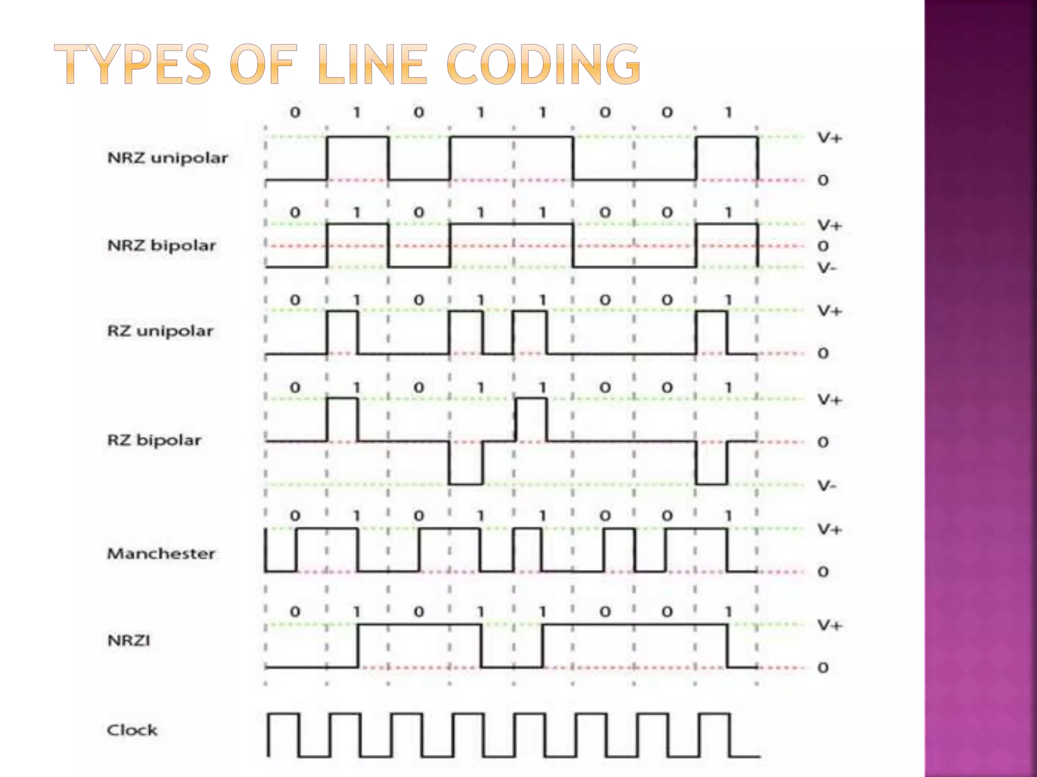
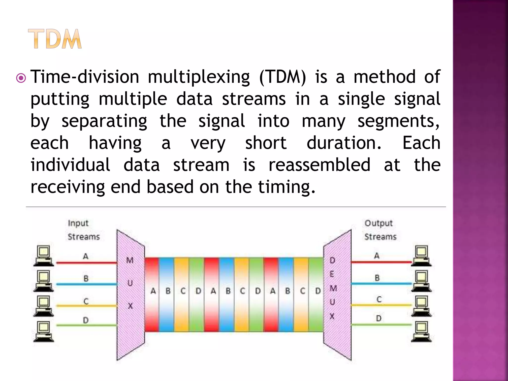
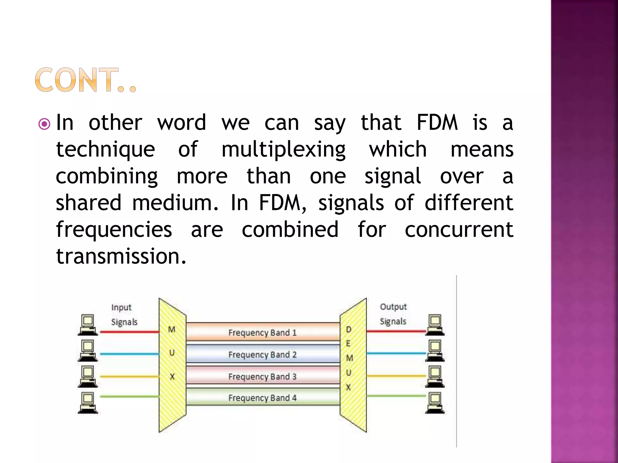
Dr. M. Rajkumar
Associate Professor,
Mrs. Remya Rose S
Assistant Professor
Department of Computer Science and
Engineering
R.M.D Engineering College.
Low pass sampling theorem
Quantization
PAM
Line coding
PCM, DPCM, DM, ADPCM and ADM,
Channel Vocoder
Time Division Multiplexing
Frequency Division Multiplexing
 In Analog modulation both carrier and
modulating signal are in analog.
 In pulse modulation ,modulation signal is a
analog signal but carrier signal is discrete
pulse signal.
 The sampling is the process of converting
analog signal into discrete pulse.
 Here analog signal is converted into a
corresponding sequence of samples that are
usually spaced uniformly in time.
 The sampling theorem can be defined as the
conversion of an analog signal into a discrete
form by taking the sampling frequency as
twice the input analog signal frequency.
 Input signal frequency denoted by fm and
sampling signal frequency denoted by fs.
fs ≥ 2fm
 The over lapping of the signal is known as
Aliasing Effect.
 To maintain sound quality in music
recordings.
 Sampling process applicable in the
conversion of analog to discrete form.
 Speech recognition systems and pattern
recognition systems.
 Modulation and Demodulation systems
 In sensor data evaluation systems
 Radar and radio navigation system sampling
is applicable.
 Digital watermarking and biometric
identification systems, surveillance systems.
 The digitization of analog signals involves the
rounding off of the values which are
approximately equal to the analog values.
The method of sampling chooses a few points
on the analog signal and then these points
are joined to round off the value to a near
stabilized value. Such a process is called as
Quantization.
 The quantizing of an analog signal is done by
discretizing the signal with a number of
quantization levels. Quantization is
representing the sampled values of the
amplitude by a finite set of levels, which
means converting a continuous-amplitude
sample into a discrete-time signal.
 The following figure shows how an analog
signal gets quantized. The blue line
represents analog signal while the brown one
represents the quantized signal.
 The following figure shows how an analog signal gets quantized.
The blue line represents analog signal while the brown one
represents the quantized signal.
13
 Pulse amplitude modulation is a technique in
which the amplitude of each pulse is
controlled by the instantaneous amplitude of
the modulation signal.
 It is a modulation system in which the signal
is sampled at regular intervals and each
sample is made proportional to the
amplitude of the signal at the instant of
sampling.
 This technique transmits the data by
encoding in the amplitude of a series of
signal pulses.
 PAM is classified into two types they are,
 Flat Top PAM
 Natural PAM
 Flat top PAM is a sampling technique. In the case
of Flat-Top pulse-amplitude modulation, the
amplitude of each pulse is made directly
proportional to the amplitude of the modulating
signal during the time of occurrence of the pulses.
This is basically done to remove noise. The top of
the amplitude of the signal will remain flat.
 In natural PAM, the amplitude of the pulse is
made directly proportional to the amplitude
of the modulating signal during the time of
pulse occurrence. The top of the amplitude
of the signal will retain the original shape of
the wave.
Advantages
 PAM is the simplest form of pulse modulation.
 Its implementation is quite easy.
Disadvantages
 The transmission bandwidth required is very
large.
 Due to the variation in amplitude, the power
required by the generating unit also varies.
 Less immune to noise due to amplitude variation.
Applications
 It is used in LED lighting, in microcontrollers in
order to produce control signals and in the
Ethernet communication system.
 A technique by which analog signal gets
converted into digital form in order to have
signal transmission through a digital network
is known as Pulse Code Modulation.
 It is abbreviated as PCM.
 Robustness to channel noise and interference;
 Efficient regeneration of the coded signal along the
transmission path;
 Efficient exchange of increased channel bandwidth for
improved signal-to-quantization noise ratio, obeying an
exponential law;
 A uniform format for the transmission of different kinds
of baseband signals, hence their integration with other
forms of digital data in a common network;
 Comparative ease with which message sources may be
dropped or reinserted in a multiplex system;
 Secure communication through the use of special
modulation schemes or encryption.
 Differential Pulse-Code Modulation (DPCM),
which exploits the use of lossy data
compression to remove the redundancy
inherent in a message signal.
 Example : voice or video
 To reduce the bit rate of the transmitted data
without serious degradation in overall system
response.
 In effect, increased system complexity is traded
off for reduced bit rate, therefore reducing the
bandwidth requirement of PCM.
In PCM for digitization of a voice or video signal, the signal is
sampled at a rate slightly higher than the Nyquist rate. The resulting
sampled signal exhibits high correlation between the adjacent
samples.
Fact: Signal does not change fast – Value from present sample to
next sample does not differ by large amount.
Adjacent samples of signal carry same information with little
difference
When this highly correlated samples are encoded in PCM System,
the resulting encoded signal contains redundant information
Removing Redundancy before encoding – Efficient coded Signal
If Redundancy reduced, overall bit rate decreases, & No of Bits
required to transmit per sample will also be reduced
DPCM Merits
 Requires less number of Quantization levels & hence less
number of bits to represent them
The signalling rate & bandwidth of a DM, DPCM System is less
than PCM System
1. Delta modulation (DM) is the simplest method for Analog-
to-Digital Conversion (ADC), closely related to DPCM.
2. Delta modulation uses 1-bit per sampling period (TS) – it
is a 1-bit ADC.
3. Delta modulation requires a sampling rate much greater
than the Nyquist rate (commonly four or five times the
Nyquist rate).
4. In DM we use a first-order predictor (one time delay TS is
the predictor).
5. DM uses very simple hardware and is low cost for that
reason.
6. The transmitted output is a binary stream of pulses. It
gives a stepwise approximation.
Delta modulation process compares the present sample value to
the previous sample value. Based upon the difference amplitude
is going to be increased or decreased by step signal. If the
amplitude is decreased/increased, then step size is
reduced/increased by one step i.e., -Δ and bit 0 is generated;
+Δ and bit 1 is generated.
DM Consists of Comparator, a Single-bit Quantizer (Hard limiter)
and an Accumulator
Delta Modulation Merits
Transmits only one bit for one sample
The signalling rate & bandwidth of a DM, DPCM System is less
than PCM System
Analog to Digital Convertor is not required
1. Slope overload Distortion
2. Granular or idle noise
Condition for avoiding slope overload
Comparison
Adaptive – Being responsive to changing level and spectrum
of the input speech signal
 A digital coding scheme that uses both Adaptive
Quantization and Adaptive Prediction is called ADPCM
 Adaptive Quantization with Forward Estimation (AQF)
 Adaptive Quantization with Backward Estimation (AQB)
 Adaptive Prediction with Forward Estimation (APF)
 Adaptive Prediction with Backward Estimation (APB)
 Line coding is the process of converting
digital data to digital signals. By this
technique we converts a sequence of bits to
a digital signal.
 At the sender side digital data are encoded
into a digital signal and at the receiver side
the digital data are recreated by decoding
the digital signal.
 Time-division multiplexing (TDM) is a method of
putting multiple data streams in a single signal
by separating the signal into many segments,
each having a very short duration. Each
individual data stream is reassembled at the
receiving end based on the timing.
 Frequency division multiplexing is a
multiplexing technique that uses different
frequencies to combine multiple streams of
data for transmission over a communications
medium.
 FDM assigns a discrete carrier frequency to
each data stream and then combines many
modulated carrier frequencies for
transmission.
 For example, television transmitters use
FDM to broadcast several channels at once.
 In other word we can say that FDM is a
technique of multiplexing which means
combining more than one signal over a
shared medium. In FDM, signals of different
frequencies are combined for concurrent
transmission.
 It allows sharing of a single transmission
medium like a copper cable or a fiber optic
cable, among multiple independent signals
generated by multiple users.
 FDM has been popularly used to multiplex
calls in telephone networks. It can also be
used in cellular networks, wireless networks
and for satellite communications.

Communication Engineering-Unit 2

  • 1.
    Dr. M. Rajkumar AssociateProfessor, Mrs. Remya Rose S Assistant Professor Department of Computer Science and Engineering R.M.D Engineering College.
  • 2.
    Low pass samplingtheorem Quantization PAM Line coding PCM, DPCM, DM, ADPCM and ADM, Channel Vocoder Time Division Multiplexing Frequency Division Multiplexing
  • 3.
     In Analogmodulation both carrier and modulating signal are in analog.  In pulse modulation ,modulation signal is a analog signal but carrier signal is discrete pulse signal.
  • 4.
     The samplingis the process of converting analog signal into discrete pulse.  Here analog signal is converted into a corresponding sequence of samples that are usually spaced uniformly in time.
  • 5.
     The samplingtheorem can be defined as the conversion of an analog signal into a discrete form by taking the sampling frequency as twice the input analog signal frequency.  Input signal frequency denoted by fm and sampling signal frequency denoted by fs. fs ≥ 2fm
  • 8.
     The overlapping of the signal is known as Aliasing Effect.
  • 9.
     To maintainsound quality in music recordings.  Sampling process applicable in the conversion of analog to discrete form.  Speech recognition systems and pattern recognition systems.  Modulation and Demodulation systems  In sensor data evaluation systems  Radar and radio navigation system sampling is applicable.  Digital watermarking and biometric identification systems, surveillance systems.
  • 10.
     The digitizationof analog signals involves the rounding off of the values which are approximately equal to the analog values. The method of sampling chooses a few points on the analog signal and then these points are joined to round off the value to a near stabilized value. Such a process is called as Quantization.
  • 11.
     The quantizingof an analog signal is done by discretizing the signal with a number of quantization levels. Quantization is representing the sampled values of the amplitude by a finite set of levels, which means converting a continuous-amplitude sample into a discrete-time signal.  The following figure shows how an analog signal gets quantized. The blue line represents analog signal while the brown one represents the quantized signal.
  • 12.
     The followingfigure shows how an analog signal gets quantized. The blue line represents analog signal while the brown one represents the quantized signal.
  • 13.
  • 14.
     Pulse amplitudemodulation is a technique in which the amplitude of each pulse is controlled by the instantaneous amplitude of the modulation signal.  It is a modulation system in which the signal is sampled at regular intervals and each sample is made proportional to the amplitude of the signal at the instant of sampling.  This technique transmits the data by encoding in the amplitude of a series of signal pulses.
  • 16.
     PAM isclassified into two types they are,  Flat Top PAM  Natural PAM
  • 17.
     Flat topPAM is a sampling technique. In the case of Flat-Top pulse-amplitude modulation, the amplitude of each pulse is made directly proportional to the amplitude of the modulating signal during the time of occurrence of the pulses. This is basically done to remove noise. The top of the amplitude of the signal will remain flat.
  • 18.
     In naturalPAM, the amplitude of the pulse is made directly proportional to the amplitude of the modulating signal during the time of pulse occurrence. The top of the amplitude of the signal will retain the original shape of the wave.
  • 20.
    Advantages  PAM isthe simplest form of pulse modulation.  Its implementation is quite easy. Disadvantages  The transmission bandwidth required is very large.  Due to the variation in amplitude, the power required by the generating unit also varies.  Less immune to noise due to amplitude variation. Applications  It is used in LED lighting, in microcontrollers in order to produce control signals and in the Ethernet communication system.
  • 21.
     A techniqueby which analog signal gets converted into digital form in order to have signal transmission through a digital network is known as Pulse Code Modulation.  It is abbreviated as PCM.
  • 23.
     Robustness tochannel noise and interference;  Efficient regeneration of the coded signal along the transmission path;  Efficient exchange of increased channel bandwidth for improved signal-to-quantization noise ratio, obeying an exponential law;  A uniform format for the transmission of different kinds of baseband signals, hence their integration with other forms of digital data in a common network;  Comparative ease with which message sources may be dropped or reinserted in a multiplex system;  Secure communication through the use of special modulation schemes or encryption.
  • 24.
     Differential Pulse-CodeModulation (DPCM), which exploits the use of lossy data compression to remove the redundancy inherent in a message signal.  Example : voice or video  To reduce the bit rate of the transmitted data without serious degradation in overall system response.  In effect, increased system complexity is traded off for reduced bit rate, therefore reducing the bandwidth requirement of PCM.
  • 25.
    In PCM fordigitization of a voice or video signal, the signal is sampled at a rate slightly higher than the Nyquist rate. The resulting sampled signal exhibits high correlation between the adjacent samples. Fact: Signal does not change fast – Value from present sample to next sample does not differ by large amount. Adjacent samples of signal carry same information with little difference When this highly correlated samples are encoded in PCM System, the resulting encoded signal contains redundant information Removing Redundancy before encoding – Efficient coded Signal If Redundancy reduced, overall bit rate decreases, & No of Bits required to transmit per sample will also be reduced
  • 27.
    DPCM Merits  Requiresless number of Quantization levels & hence less number of bits to represent them The signalling rate & bandwidth of a DM, DPCM System is less than PCM System
  • 28.
    1. Delta modulation(DM) is the simplest method for Analog- to-Digital Conversion (ADC), closely related to DPCM. 2. Delta modulation uses 1-bit per sampling period (TS) – it is a 1-bit ADC. 3. Delta modulation requires a sampling rate much greater than the Nyquist rate (commonly four or five times the Nyquist rate). 4. In DM we use a first-order predictor (one time delay TS is the predictor). 5. DM uses very simple hardware and is low cost for that reason. 6. The transmitted output is a binary stream of pulses. It gives a stepwise approximation.
  • 29.
    Delta modulation processcompares the present sample value to the previous sample value. Based upon the difference amplitude is going to be increased or decreased by step signal. If the amplitude is decreased/increased, then step size is reduced/increased by one step i.e., -Δ and bit 0 is generated; +Δ and bit 1 is generated.
  • 30.
    DM Consists ofComparator, a Single-bit Quantizer (Hard limiter) and an Accumulator
  • 31.
    Delta Modulation Merits Transmitsonly one bit for one sample The signalling rate & bandwidth of a DM, DPCM System is less than PCM System Analog to Digital Convertor is not required
  • 32.
    1. Slope overloadDistortion 2. Granular or idle noise Condition for avoiding slope overload
  • 33.
  • 34.
    Adaptive – Beingresponsive to changing level and spectrum of the input speech signal  A digital coding scheme that uses both Adaptive Quantization and Adaptive Prediction is called ADPCM  Adaptive Quantization with Forward Estimation (AQF)  Adaptive Quantization with Backward Estimation (AQB)  Adaptive Prediction with Forward Estimation (APF)  Adaptive Prediction with Backward Estimation (APB)
  • 37.
     Line codingis the process of converting digital data to digital signals. By this technique we converts a sequence of bits to a digital signal.  At the sender side digital data are encoded into a digital signal and at the receiver side the digital data are recreated by decoding the digital signal.
  • 40.
     Time-division multiplexing(TDM) is a method of putting multiple data streams in a single signal by separating the signal into many segments, each having a very short duration. Each individual data stream is reassembled at the receiving end based on the timing.
  • 41.
     Frequency divisionmultiplexing is a multiplexing technique that uses different frequencies to combine multiple streams of data for transmission over a communications medium.  FDM assigns a discrete carrier frequency to each data stream and then combines many modulated carrier frequencies for transmission.  For example, television transmitters use FDM to broadcast several channels at once.
  • 42.
     In otherword we can say that FDM is a technique of multiplexing which means combining more than one signal over a shared medium. In FDM, signals of different frequencies are combined for concurrent transmission.
  • 43.
     It allowssharing of a single transmission medium like a copper cable or a fiber optic cable, among multiple independent signals generated by multiple users.  FDM has been popularly used to multiplex calls in telephone networks. It can also be used in cellular networks, wireless networks and for satellite communications.