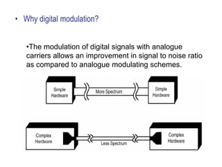
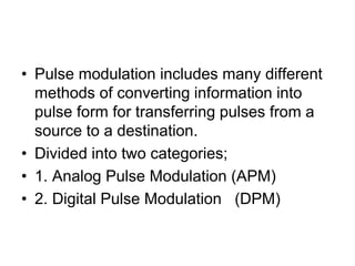
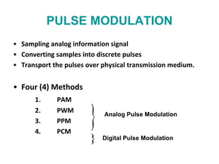
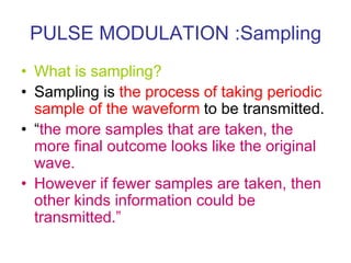
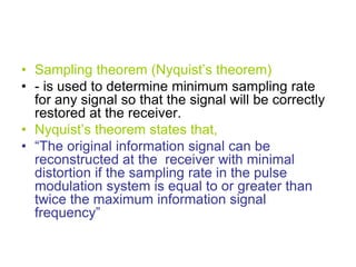
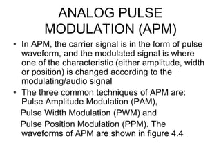
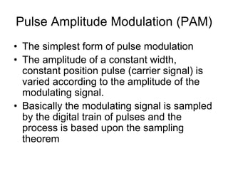
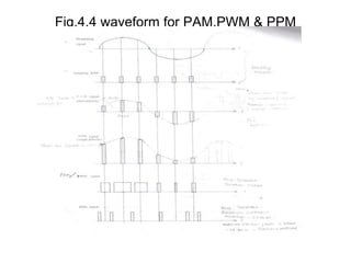
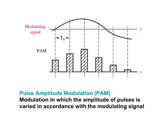
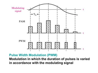
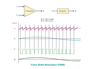
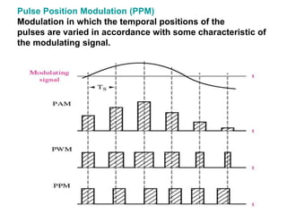
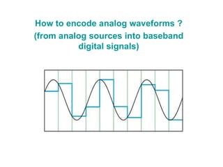
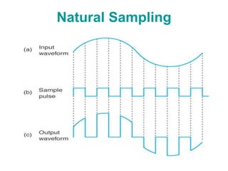
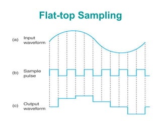
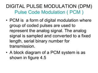
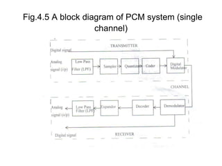
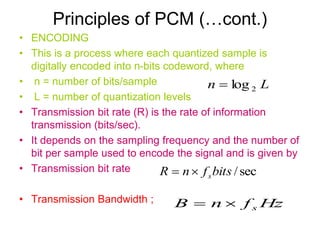
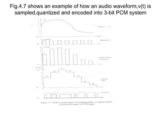
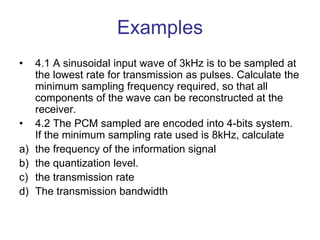
"Advanced Digital Modulation Techniques" explores cutting-edge methods shaping modern communication systems. This comprehensive guide delves into intricate algorithms and protocols enhancing data transmission efficiency and reliability. From phase-shift keying (PSK) to quadrature amplitude modulation (QAM), readers uncover the intricate nuances of signal modulation, demodulation, and error correction. The text navigates through the evolution of digital modulation, shedding light on emerging trends like orthogonal frequency-division multiplexing (OFDM) and software-defined radio (SDR). Engineers, researchers, and students alike benefit from practical insights, case studies, and simulations, empowering them to design, optimize, and troubleshoot complex digital communication systems in today's dynamic technological landscape.
Azure Monitor & Application Insight to monitor Infrastructure & Application
DIGITALModulation.pptx "Advanced Digital Modulation Techniques"
1.
2. • Digital modulation
– Is the transmittal of digitally modulated analog signals
between two or more points in a communications system.
– Can be propagated through Earth’s atmosphere and used in
wireless communication system - digital radio.
– Offer several outstanding advantages over traditional analog
system.
• Ease of processing
• Ease of multiplexing
• Noise immunity
3. • Applications:
• Low speed voice band data comm.
modems
• High speed data transmission systems
• Digital microwave & satellite comm.
systems
• PCS (personal communication systems)
telephone
4. • Why digital modulation?
•The modulation of digital signals with analogue
carriers allows an improvement in signal to noise ratio
as compared to analogue modulating schemes.
5. • Important Criteria
1. High spectral efficiency
2. High power efficiency
3. Robust to multipath
4. Low cost and ease of implementation
5. Low carrier-to-co channel
interference ratio
6. Low out-of-band radiation
6. 7. Constant or near constant envelop
8. Bandwidth Efficiency
• Ability to accommodate data within a limited
bandwidth
• Tradeoff between data rate and pulse width
9. Power Efficiency
• To preserve the fidelity of the digital message at low
power levels.
• Can increase noise immunity by increasing signal
power
8. • Pulse modulation includes many different
methods of converting information into
pulse form for transferring pulses from a
source to a destination.
• Divided into two categories;
• 1. Analog Pulse Modulation (APM)
• 2. Digital Pulse Modulation (DPM)
9. PULSE MODULATION
• Sampling analog information signal
• Converting samples into discrete pulses
• Transport the pulses over physical transmission medium.
• Four (4) Methods
1. PAM
2. PWM
3. PPM
4. PCM
Analog Pulse Modulation
Digital Pulse Modulation
10. PULSE MODULATION :Sampling
• What is sampling?
• Sampling is the process of taking periodic
sample of the waveform to be transmitted.
• “the more samples that are taken, the
more final outcome looks like the original
wave.
• However if fewer samples are taken, then
other kinds information could be
transmitted.”
11. • Sampling theorem (Nyquist’s theorem)
• - is used to determine minimum sampling rate
for any signal so that the signal will be correctly
restored at the receiver.
• Nyquist’s theorem states that,
• “The original information signal can be
reconstructed at the receiver with minimal
distortion if the sampling rate in the pulse
modulation system is equal to or greater than
twice the maximum information signal
frequency”
12. •
• sampling frequency
•
• fs=sampling frequency and
• fm(max) = maximun frequency of the modulating
signal.
m
s f
f 2
13. • Basic condition of sampling process
• 1) sampling at Fs =2fm(max)
• fs 2fs
• figure 4.1 :
• Frequency spectrum of modulating signal when sampled
at fs=2fm(max)
V( Volts)
14. • When the modulating is sampled at a
minimum sampling frequency, the
frequency spectrum is as shown in figure
4.1.
• In practice it is difficult to design a low
pass filter, in order to restore the original
modulating signal
15. • 2) sampling at fs> 2fm(max)
• This sampling rate creates a guard band between fm(max)
and the lowest frequency component (fs-fm(max)) of the
sampling harmonics.
• Therefore a more practical LPF can be used to restore the
modulating signal.
• Figure 4.2 Sampling at fs> 2fm(max)
16. • Sampling at fs < 2fm(max)
• When the sampling rate is less than the minimum
value, distortion will occurs. This distortion is called
aliasing.
• Figure 4.3 Sampling at fs < 2fm(max)
17. • Aliasing effect can be eliminated by using an anti-aliasing filter prior to
sampling and using a sampling rate slightly higher than Nyquist rate
(fs=2W).
)
(t
g
Anti-aliasing
Filter
Sampler
)
( s
kT
g
18. ANALOG PULSE
MODULATION (APM)
• In APM, the carrier signal is in the form of pulse
waveform, and the modulated signal is where
one of the characteristic (either amplitude, width
or position) is changed according to the
modulating/audio signal
• The three common techniques of APM are:
Pulse Amplitude Modulation (PAM),
Pulse Width Modulation (PWM) and
Pulse Position Modulation (PPM). The
waveforms of APM are shown in figure 4.4
19. Pulse Amplitude Modulation (PAM)
• The simplest form of pulse modulation
• The amplitude of a constant width,
constant position pulse (carrier signal) is
varied according to the amplitude of the
modulating signal.
• Basically the modulating signal is sampled
by the digital train of pulses and the
process is based upon the sampling
theorem
21. Pulse Width Modulation (PWM)
• The technique of varying the width of the
constant amplitude pulse proportional to
the amplitude of the modulation signal.
• Also known as Pulse Duration Modulation
(FDM).
• Either the leading edge, trailing edge or
both may be varied by the modulating
signal.
22. Pulse Width Modulation (PWM)
• PWM gives better signal to noise
performance than PAM.
• PWM has advantage, when compared
with PPM, that is its pulse are of varying
width and therefore of varying power
content. PWM still works if synchronization
between transmitter and receiver fails,
whereas PPM does not.
23. Pulse Position Modulation (PPM)
• PPM is when the position of a constant-width
and constant-amplitude pulse within prescribed
time slot is varied according to the amplitude of
the modulating signal.
• PPM has the advantage of requiring constant
transmitter power output, but the disavantage of
depending on transmitter-receiver
synchronization.
• PPM has less noise due to amplitude changes,
becaused the received pulses may be clipped at
the receiver, thus removing amplitudeschanges
caused by noise.
24. Pulse Amplitude Modulation (PAM)
Modulation in which the amplitude of pulses is
varied in accordance with the modulating signal
25. Pulse Width Modulation (PWM)
Modulation in which the duration of pulses is varied
in accordance with the modulating signal
27. Pulse Position Modulation (PPM)
Modulation in which the temporal positions of the
pulses are varied in accordance with some characteristic of
the modulating signal.
28. How to encode analog waveforms ?
(from analog sources into baseband
digital signals)
31. DIGITAL PULSE MODULATION (DPM)
Pulse Code Modulation ( PCM )
• PCM is a form of digital modulation where
group of coded pulses are used to
represent the analog signal. The analog
signal is sampled and converted to a fixed
length, serial binary number for
transmission.
• A block diagram of a PCM system is as
shown in figure 4.5
33. Principles of PCM
• Three main process in PCM transmission
are sampling, quantization and coding.
• 1. Sampling – is a process of taking
samples of information signal at a rate of
Nyquist’s sampling frequency.
• 2. Quantization – is a process of assigning
the analog signal samples to a pre-
determined discrete levels. The number of
quantization levels ,L, depends on the
number of bits per sample, n, used to code
the signal. Where
n
L 2
34. Principles of PCM (…cont.)
• The magnitude of the minimum stepsize of the
quantization levels is called resolution,
• It is equal in magnitude to the voltage of the
least significant bit of the magnitude stepsize of
the digital to analog converter (DAC). The
resolution depends on the maximum voltage,
Vmax, and the minimum voltage Vmin of the
information signal, where
V
1
min
max
L
V
V
V
35. Principles of PCM (…cont.)
• Quantization error or quantization noise is the distortion
introduced during the quantization process when the
modulating signal is not an exact value of the quantized level.
It is the difference between original signal and the quantized
signal magnitude that is :
• Quantization error, Qe = |x(t)| - |q(t)|
• Where |x(t)| is the magnitude of original signal
• Where |q(t)| is the magnitude of quantized signal
• The maximum quantization error,
• Quantization error can be reduced by increasing the number of
quantization level BUT this will increase the bandwidth
required.
2
max
V
Qe
36. Principles of PCM (…cont.)
• ENCODING
• This is a process where each quantized sample is
digitally encoded into n-bits codeword, where
• n = number of bits/sample
• L = number of quantization levels
• Transmission bit rate (R) is the rate of information
transmission (bits/sec).
• It depends on the sampling frequency and the number of
bit per sample used to encode the signal and is given by
• Transmission bit rate
• Transmission Bandwidth ;
L
n 2
log
sec
/
bits
f
n
R s
Hz
f
n
B s
37. Fig.4.7 shows an example of how an audio waveform,v(t) is
sampled,quantized and encoded into 3-bit PCM system
38. Examples
• 4.1 A sinusoidal input wave of 3kHz is to be sampled at
the lowest rate for transmission as pulses. Calculate the
minimum sampling frequency required, so that all
components of the wave can be reconstructed at the
receiver.
• 4.2 The PCM sampled are encoded into 4-bits system.
If the minimum sampling rate used is 8kHz, calculate
a) the frequency of the information signal
b) the quantization level.
c) the transmission rate
d) The transmission bandwidth