Download as PDF, PPTX


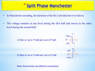
![*Split Phase Manchester
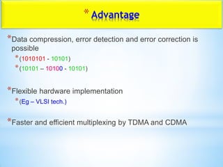
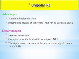
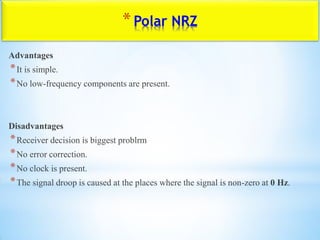
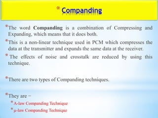
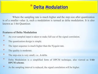
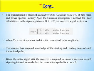
Advantages
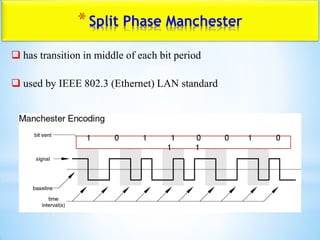
synchronization on mid bit transition (self clocking codes)
has no dc component
has error detection capability (the absence of an expected transition can be
used to detect errors)
Disadvantages
at least one transition per bit time and possibly two
maximum modulation rate is twice NRZ
requires more bandwidth
elementssignalperbitsofnumberL
bpsRateDataRbaudrateModulationD
L
R
D
:
];[,:];[,:
](https://image.slidesharecdn.com/unit-1-basebandtransmission-200403091028/85/Base-band-transmission-71-320.jpg)
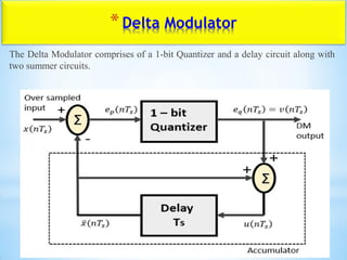
![*Delta Modulator
*Using these notations, now we shall try to figure out the process of delta
modulation.
ep(nTs) = x(nTs)−x^(nTs) -eq. 1
𝑖𝑓 x(nTs) > x^(nTs) = ∆
else
x(nTs) < x^(nTs) = −∆
= x(nTs)−u([n−1]Ts)
= x(nTs)−[x^[[n−1]Ts]+v[[n−1]Ts]] -eq. 2
*Further,
v(nTs) = eq(nTs) -eq. 3
u(nTs) = xˆ(nTs)+eq(nTs)](https://image.slidesharecdn.com/unit-1-basebandtransmission-200403091028/85/Base-band-transmission-93-320.jpg)
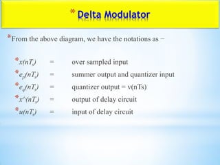
![*Delta Modulator
*Where,
x^(nTs) = the previous value of the delay circuit
eq(nTs) = Quantizer output = v(nTs)
*Hence,
u(nTs)=u([n−1]Ts)+v(nTs) ---------equation 4
Which means,
The present input of the delay unit
= The previous output of the delay unit
+ the present Quantizer output](https://image.slidesharecdn.com/unit-1-basebandtransmission-200403091028/85/Base-band-transmission-94-320.jpg)

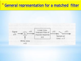

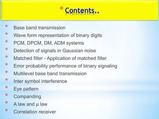
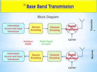
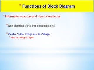
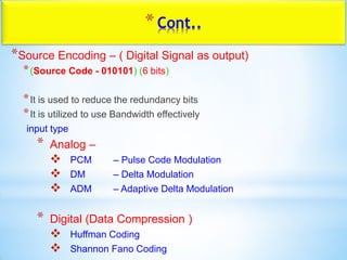
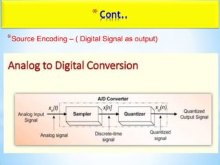
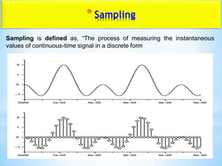
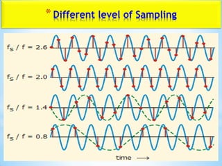
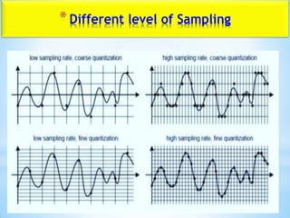
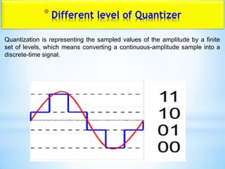
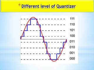
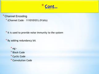
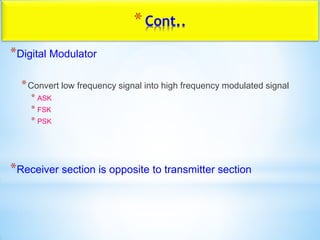
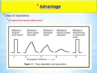
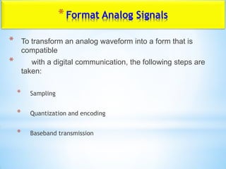
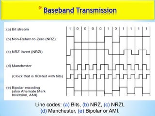
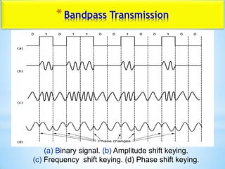
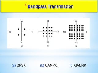
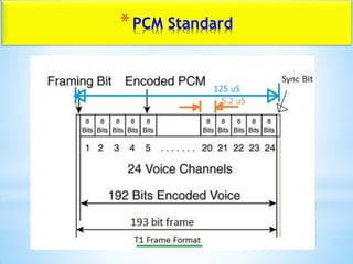
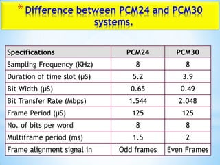
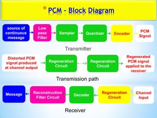
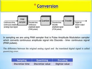
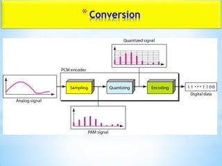
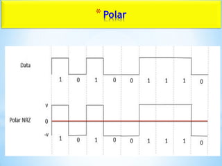
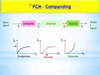
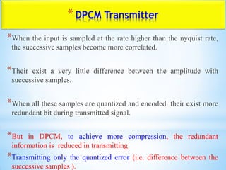
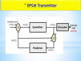
The document provides information about baseband transmission in digital communication. It discusses various concepts related to baseband transmission including: pulse code modulation (PCM) systems, source encoding, sampling, quantization, channel encoding, digital modulation, and line coding techniques such as NRZ and RZ. The key steps in baseband transmission are described as: converting the analog signal to digital using sampling and quantization, encoding the digital signal, modulating the encoded digital signal to transmit over the channel, and demodulating and decoding at the receiver to reconstruct the original analog signal.