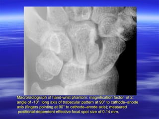
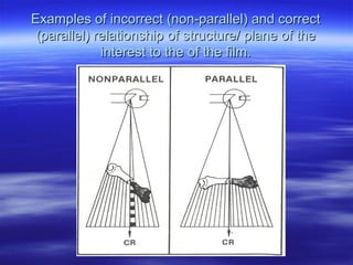
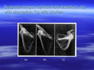
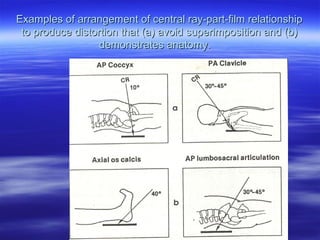
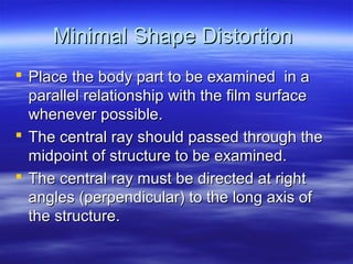
Distortion
Distortion
 Unequal magnification of different portions
of the same object.
 Two types of distortion:
1.Size distortion
2.Shape distortion
Size Distortion
 Refers mispresentation of actual size of the structure as
recorded on the film. Another term for size distortion is
magnification.
 Size distortion influenced by :
a) OFD
b) FFD
 Formula to calculate size distortion

image width
FFD

---------------- = -------
Object width
FOD
Example of calculation of the amount
of magnification of an image width,
object width.
Magnification resulting from different
OFD
Magnification resulting from different
FFD.
Minimal Distortion Radiography
 Size Distortion:
 Always place the structure to be examined
as close to the film as possible.
 Use a standardize FFD for all radiographic
procedures. This should be the greatest
distance consistent with the x-ray tube
output and demands of the procedure with
regard to motion control.
Size Distortion Used to Advantage
 In angiography to visualize small blood
vessel.
 In macroradiography to visualize early bone
destruction .
How is magnification achieved?
 By increasing the distance between the
anatomy to be radiographed and the image
receptor (OID)
Magnification Radiography
 Can be intentional or unintentional
 Unintentional:
– Occurs when the film cannot be placed near the body part being
radiographed

 Intentional Uses
–
–
–
–

Vascular imaging
Neuroradiology
Orthopedics
Mammography
The Magnification Factor
 The means of determining how much the
image will be magnified
 Magnification = SID/SOD or SID/SID - OID
Technical Requirements for
Magnification
 A small focal spot must be used
– App. 0.3mm or less

 Grids are not necessary as the increased
OID utilizes the air gap technique
 Low mA must be used
Disadvantages of Magnification
Radiography
 Patient dose is increased
 To obtain a magnification factor of 2, the
patient must be placed halfway between the
film and tube
 A magnification factor of 2 increases patient
dose by a factor of 4
Macroradiograph of hand-wrist phantom: magnification factor of 2; angle of 10°;
long axis of trabecular pattern at 90° to cathode–anode axis (fingers pointing at
90° to cathode–anode axis); measured positional-dependent effective focal spot
size of
0.14 mm.
Macroradiograph of hand-wrist phantom: magnification factor of 2; angle of 0°;
measured positional-dependent effective focal spot size of 0.76 mm.
Macroradiograph of hand-wrist phantom: magnification factor of 2;
angle of -10°; long axis of trabecular pattern at 90° to cathode–anode
axis (fingers pointing at 90° to cathode–anode axis); measured
positional-dependent effective focal spot size of 0.14 mm.
Shape Distortion
 Often referred to a true distortion, caused
by elongation or foreshortening in
radiographic image.
 Shape distortion influenced by:
 (a) Part- film relationship.
 (b) Central ray- part-film alignment.
 (c) Central ray direction.
Examples of incorrect (non-parallel) and correct
(parallel) relationship of structure/ plane of the
interest to the of the film.
Examples of good (centered) and poor (off-center)
alignment of the central ray, the body part, and the
film.
Examples of proper (left) and improper (right)
direction of the central ray alignment to the structure/
plane of interest.
Scapular images (a) free from distortion, (b)
with elongation, (c) with shorten

(a)

(b)

(c)
Shape Distortion Used to advantage

 To avoid superimposition.
 To demonstrate anatomy.
Examples of arrangement of central ray-part-film relationship
to produce distortion that (a) avoid superimposition and (b)
demonstrates anatomy.
Minimal Shape Distortion
 Place the body part to be examined in a
parallel relationship with the film surface
whenever possible.
 The central ray should passed through the
midpoint of structure to be examined.
 The central ray must be directed at right
angles (perpendicular) to the long axis of
the structure.
THANKS

Distortion

  • 1.
  • 2.
    Distortion  Unequal magnificationof different portions of the same object.  Two types of distortion: 1.Size distortion 2.Shape distortion
  • 3.
    Size Distortion  Refersmispresentation of actual size of the structure as recorded on the film. Another term for size distortion is magnification.  Size distortion influenced by : a) OFD b) FFD  Formula to calculate size distortion  image width FFD  ---------------- = ------- Object width FOD
  • 4.
    Example of calculationof the amount of magnification of an image width, object width.
  • 5.
  • 6.
  • 7.
    Minimal Distortion Radiography Size Distortion:  Always place the structure to be examined as close to the film as possible.  Use a standardize FFD for all radiographic procedures. This should be the greatest distance consistent with the x-ray tube output and demands of the procedure with regard to motion control.
  • 8.
    Size Distortion Usedto Advantage  In angiography to visualize small blood vessel.  In macroradiography to visualize early bone destruction .
  • 9.
    How is magnificationachieved?  By increasing the distance between the anatomy to be radiographed and the image receptor (OID)
  • 10.
    Magnification Radiography  Canbe intentional or unintentional  Unintentional: – Occurs when the film cannot be placed near the body part being radiographed  Intentional Uses – – – – Vascular imaging Neuroradiology Orthopedics Mammography
  • 11.
    The Magnification Factor The means of determining how much the image will be magnified  Magnification = SID/SOD or SID/SID - OID
  • 12.
    Technical Requirements for Magnification A small focal spot must be used – App. 0.3mm or less  Grids are not necessary as the increased OID utilizes the air gap technique  Low mA must be used
  • 13.
    Disadvantages of Magnification Radiography Patient dose is increased  To obtain a magnification factor of 2, the patient must be placed halfway between the film and tube  A magnification factor of 2 increases patient dose by a factor of 4
  • 14.
    Macroradiograph of hand-wristphantom: magnification factor of 2; angle of 10°; long axis of trabecular pattern at 90° to cathode–anode axis (fingers pointing at 90° to cathode–anode axis); measured positional-dependent effective focal spot size of 0.14 mm.
  • 15.
    Macroradiograph of hand-wristphantom: magnification factor of 2; angle of 0°; measured positional-dependent effective focal spot size of 0.76 mm.
  • 16.
    Macroradiograph of hand-wristphantom: magnification factor of 2; angle of -10°; long axis of trabecular pattern at 90° to cathode–anode axis (fingers pointing at 90° to cathode–anode axis); measured positional-dependent effective focal spot size of 0.14 mm.
  • 17.
    Shape Distortion  Oftenreferred to a true distortion, caused by elongation or foreshortening in radiographic image.  Shape distortion influenced by:  (a) Part- film relationship.  (b) Central ray- part-film alignment.  (c) Central ray direction.
  • 18.
    Examples of incorrect(non-parallel) and correct (parallel) relationship of structure/ plane of the interest to the of the film.
  • 19.
    Examples of good(centered) and poor (off-center) alignment of the central ray, the body part, and the film.
  • 20.
    Examples of proper(left) and improper (right) direction of the central ray alignment to the structure/ plane of interest.
  • 21.
    Scapular images (a)free from distortion, (b) with elongation, (c) with shorten (a) (b) (c)
  • 22.
    Shape Distortion Usedto advantage  To avoid superimposition.  To demonstrate anatomy.
  • 23.
    Examples of arrangementof central ray-part-film relationship to produce distortion that (a) avoid superimposition and (b) demonstrates anatomy.
  • 24.
    Minimal Shape Distortion Place the body part to be examined in a parallel relationship with the film surface whenever possible.  The central ray should passed through the midpoint of structure to be examined.  The central ray must be directed at right angles (perpendicular) to the long axis of the structure.
  • 25.