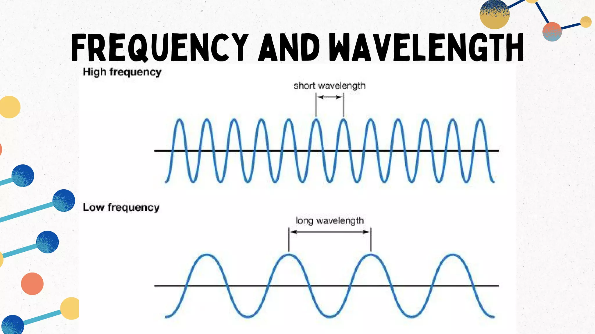
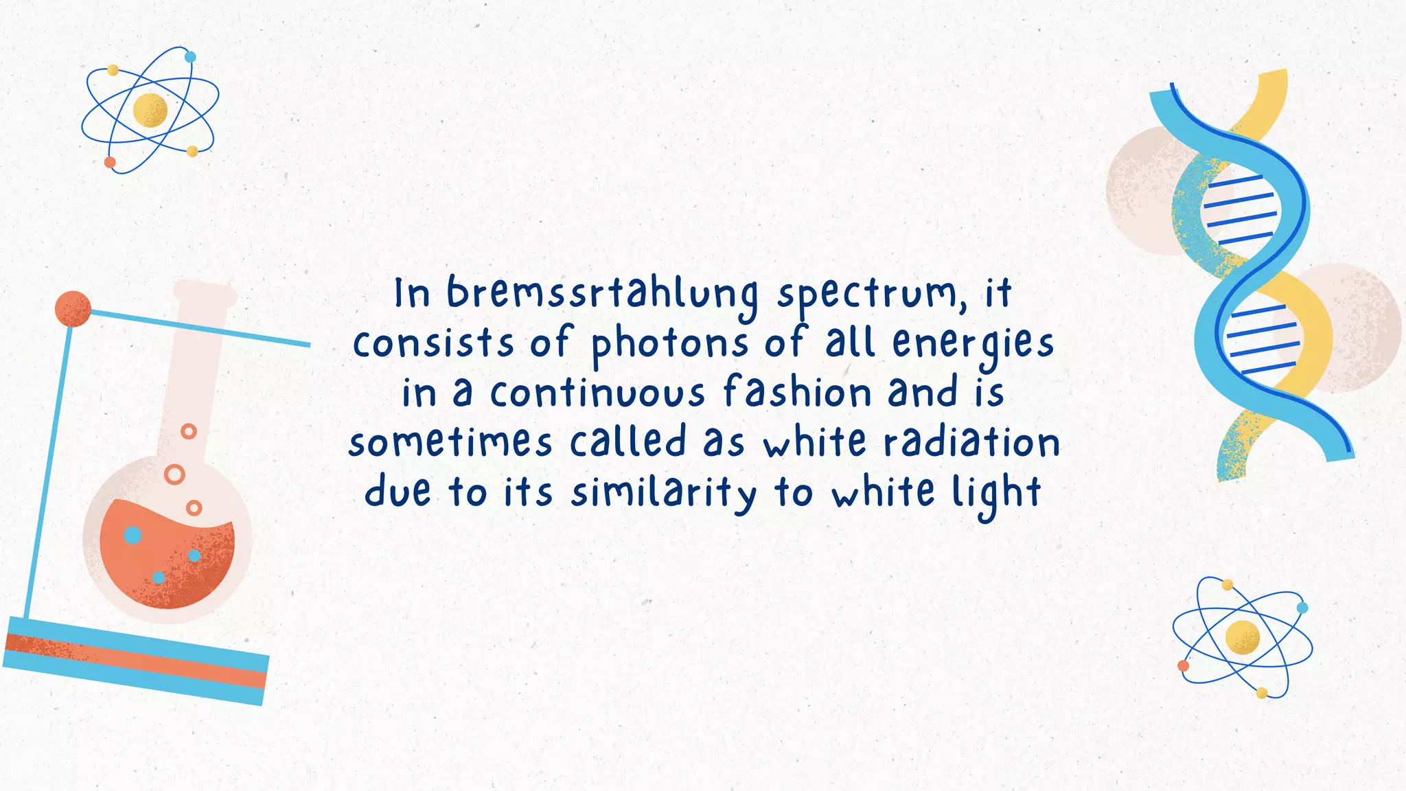
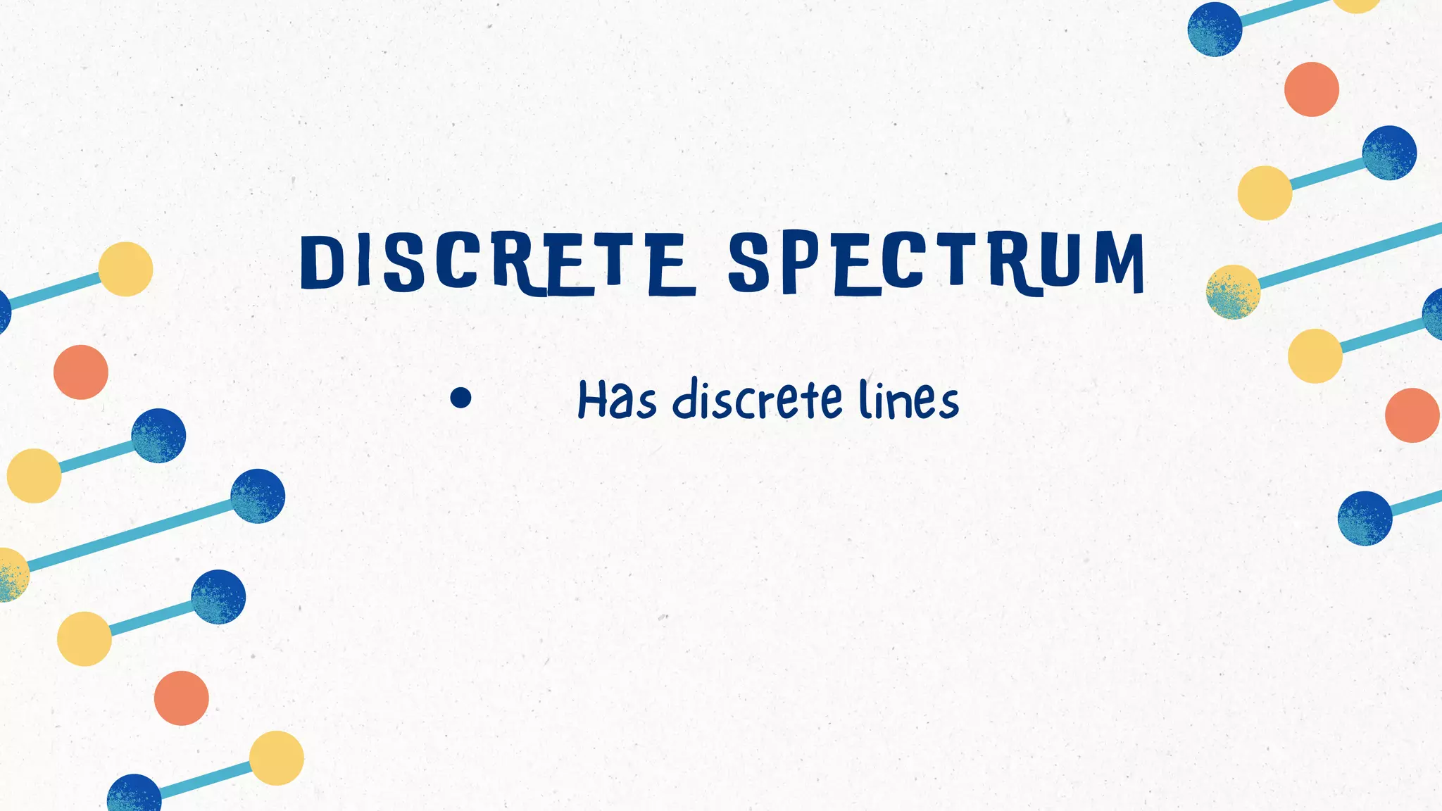
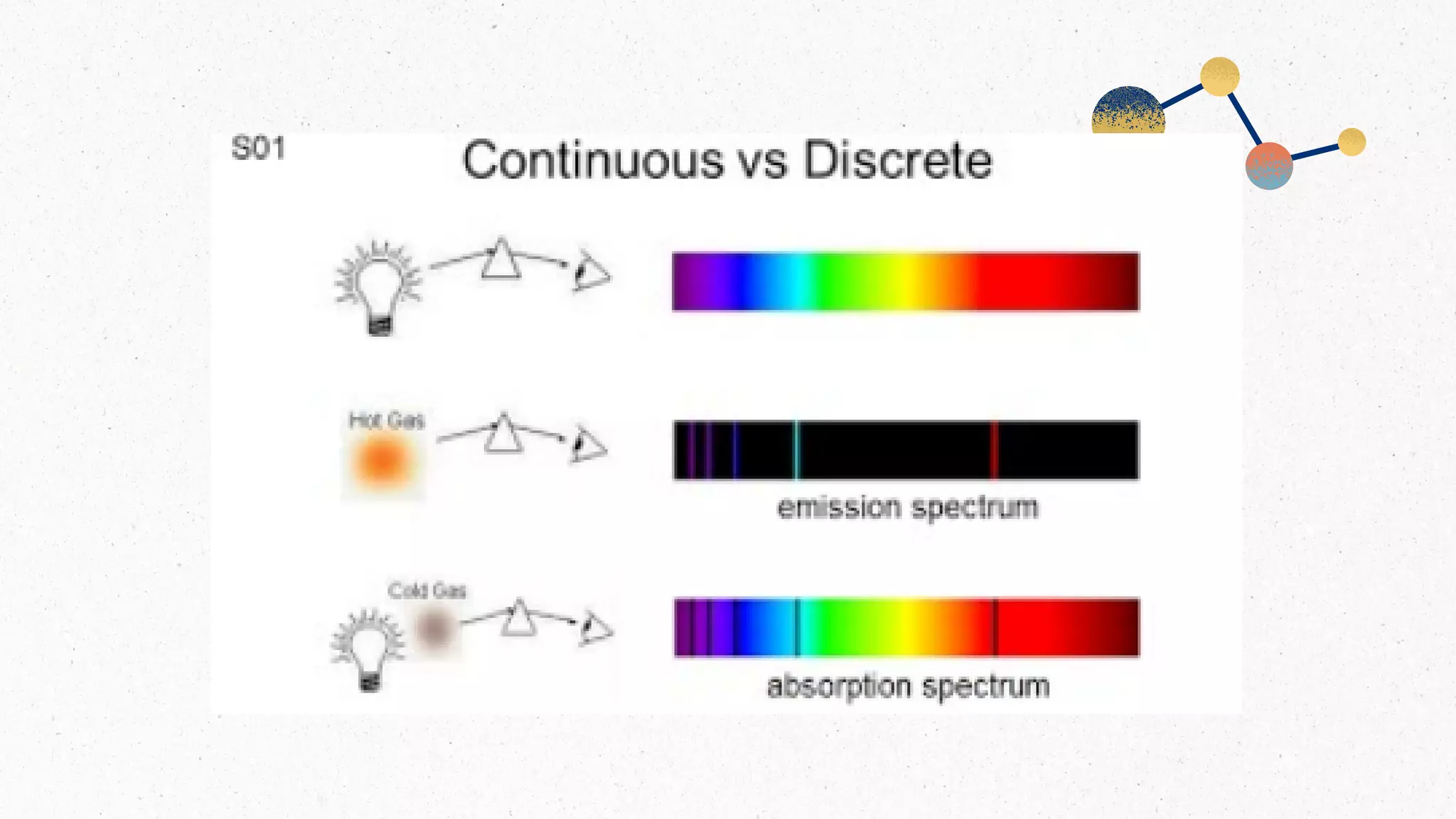
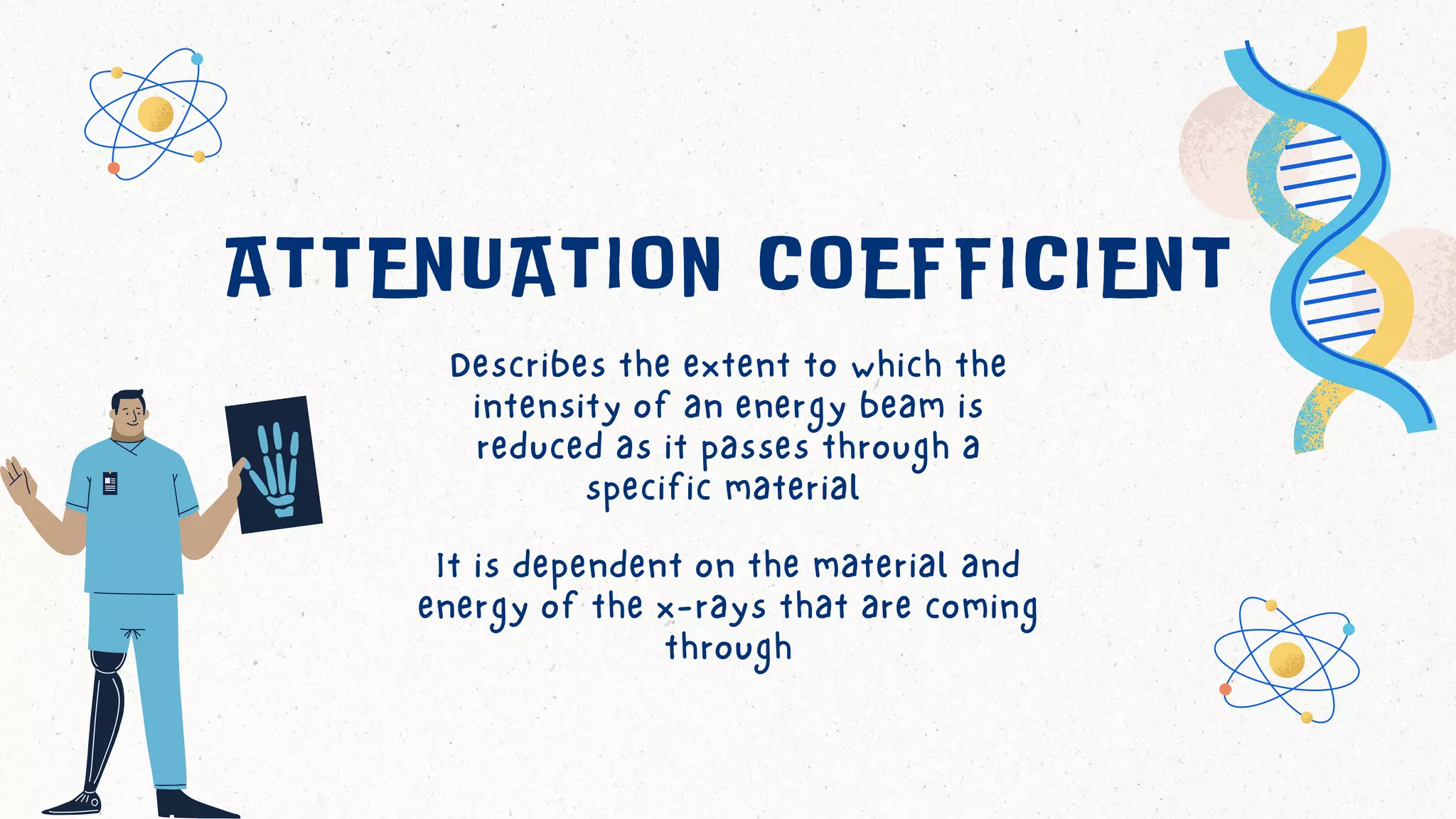
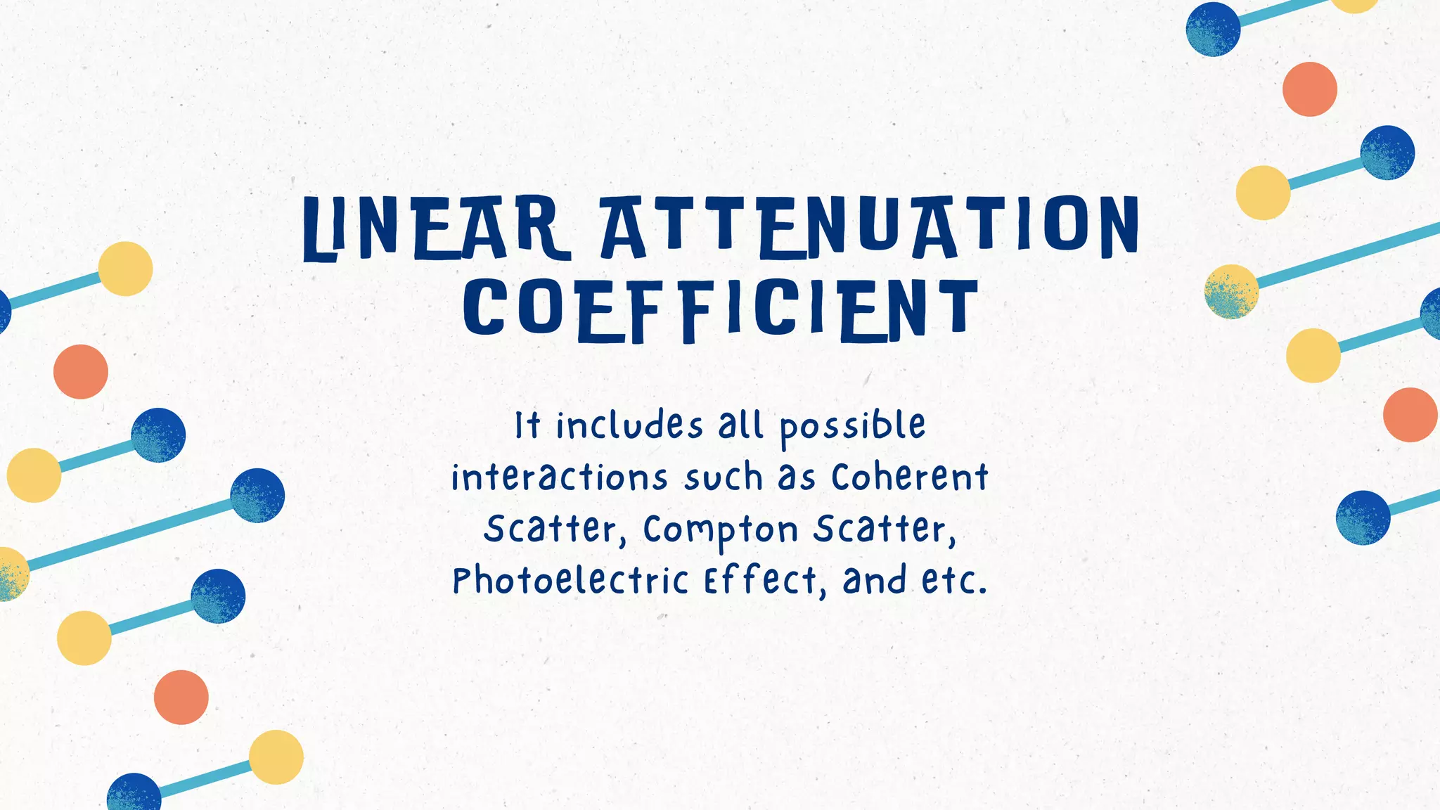
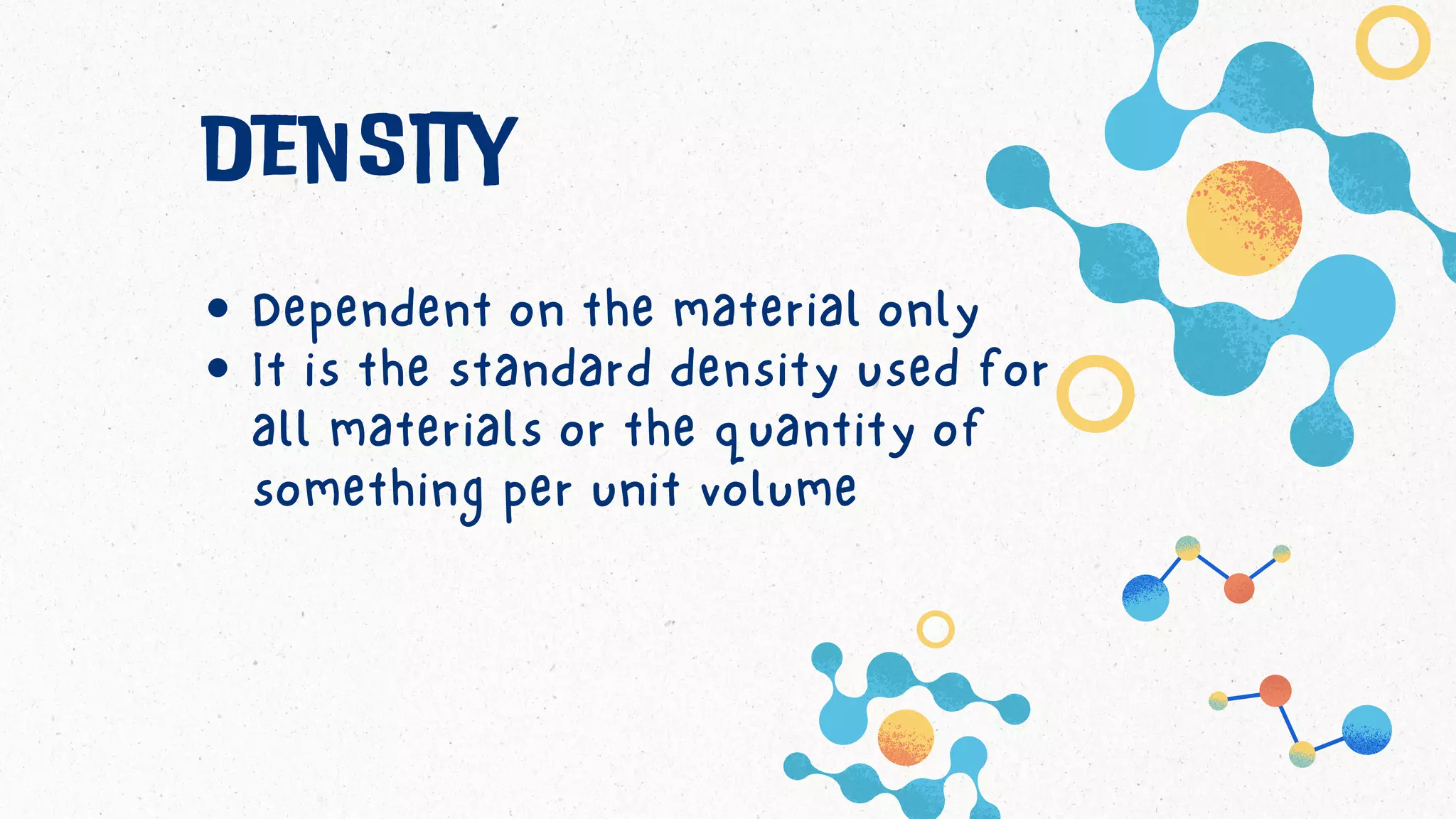
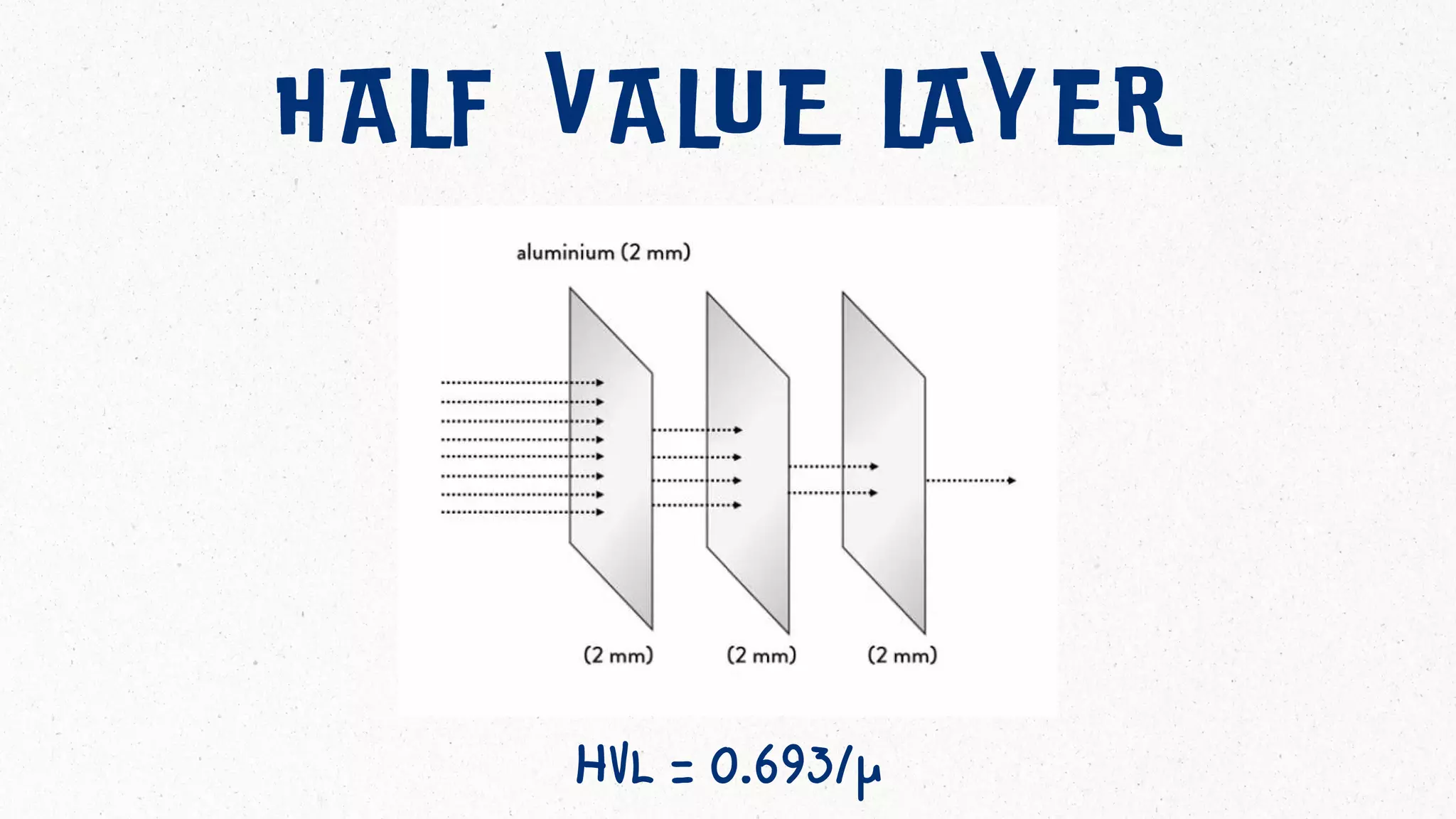
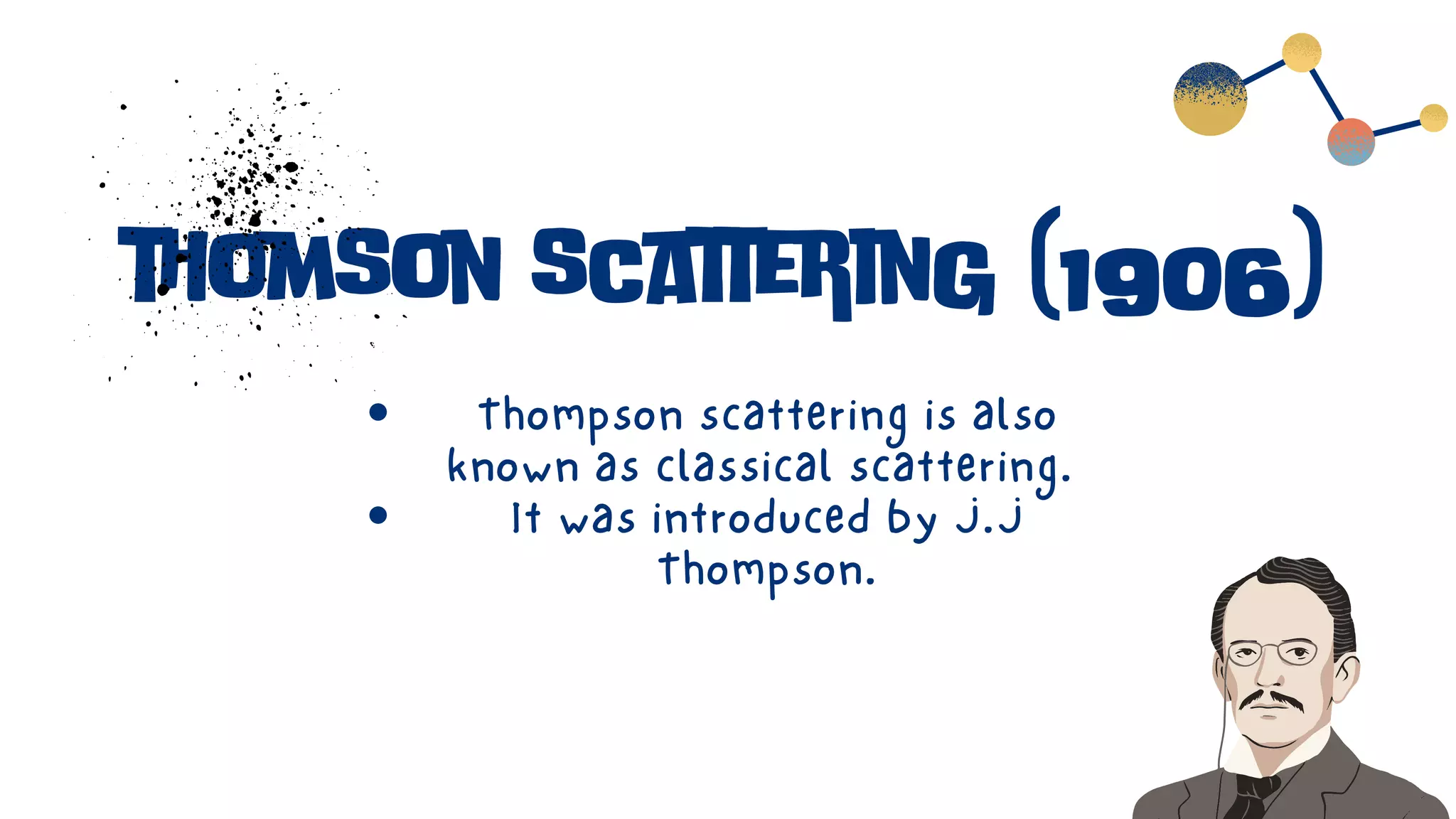
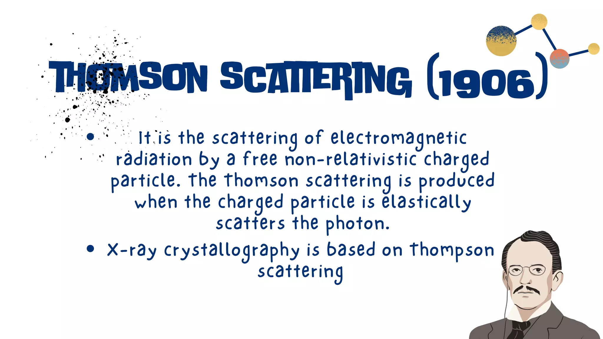
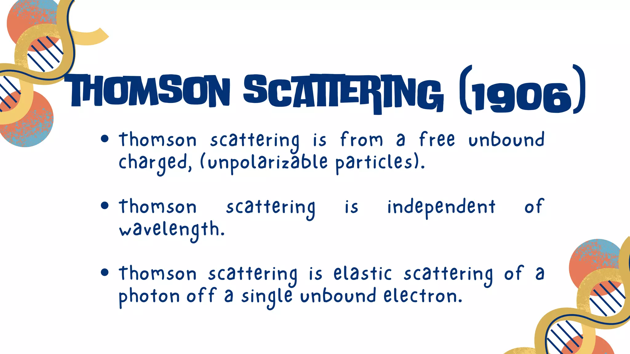
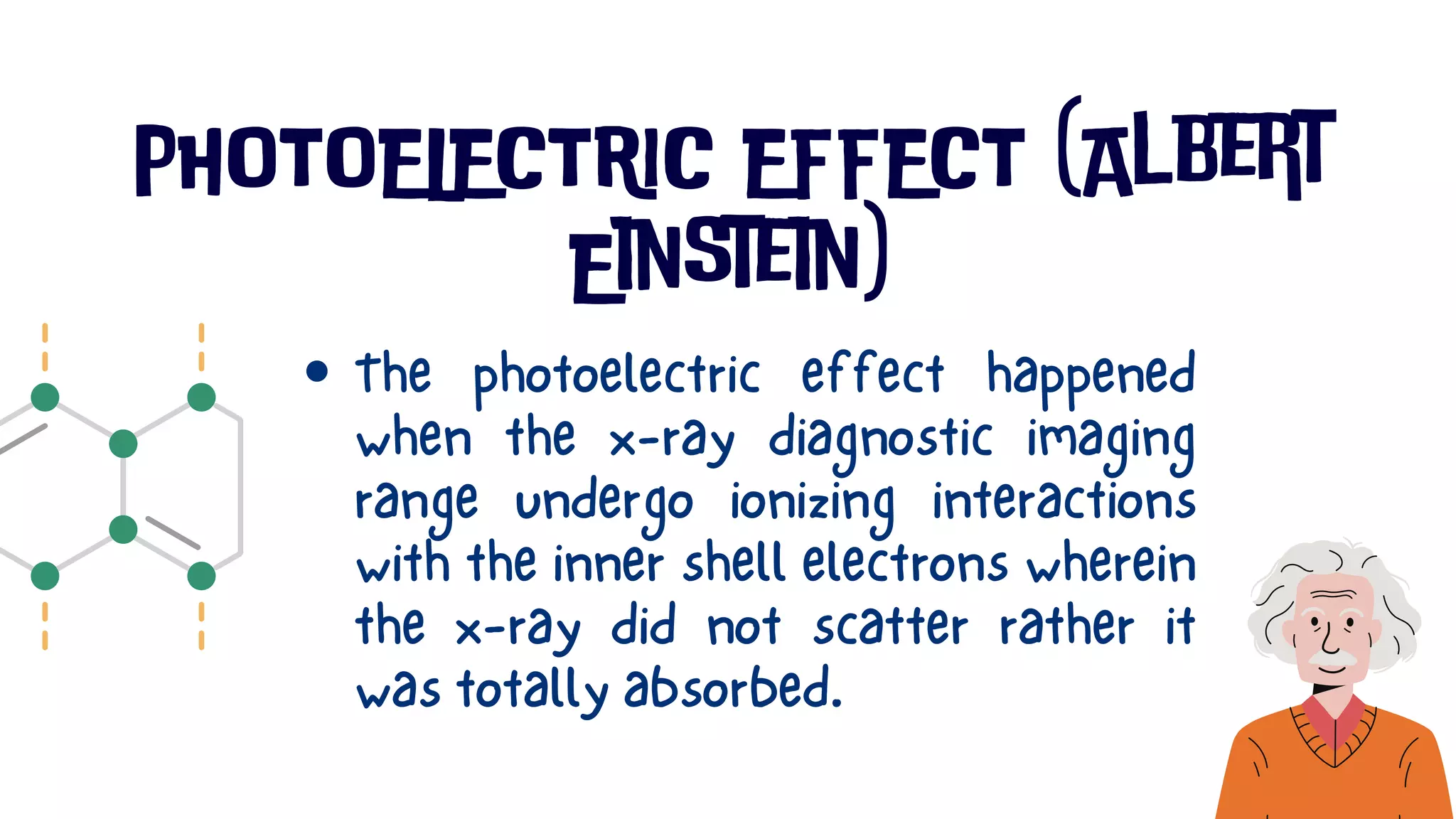
rad 104
GROUP 8
OBJECTIVES
UNDERSTAND EXPOSURE INDEX
LEARN ABOUT THE FACTORS AFFECTING RECEPTOR
EXPOSURE
LEARN THE FORMULA FOR RECEPTOR EXPOSURE
LEARN HOW TO CALCULATE RECEPTOR EXPOSURE
UNDERSTAND THE DIFFERENCE BETWEEN THE IMAGE
PROCESSING IN DIGITAL AND MANUAL RADIOGRAPH
LEARN ABOUT THE IMPORTANCE OF COLLIMATION
exposure factor
formulation
GROUP 8
EXPOSURE
INDEX
FORMULATION
RECEPTOR EXPOSURE
STANDARDIZATION
amount of radiation that
strikes the image receptor
DEFINITION
RECEPTO
R
EXPOSURE
EXPOSURE INDEX
Exposure index measures the amount of photons
that reach the image receptor in the relative region. If
the EI value is below the normal range, the
radiograph is considered as underexposed resulting
to quantum mottle and may appear “grainy”. being
overexposed would cause dose creep or the
administration of excess radiation to a patient.
UNDER
EXPOSURE
NOISE AND MOTTLE
(ARTIFACTS)
technical factor that technologists use to
control receptor exposure
MAS
mAs, collimation, and filtration
FACTORS THAT
AFFECT RECEPTOR
EXPOSURE
change the kVp to double the expopsure
15% RULE
A radiograph of the form is acquired using
2.5mA at 60 kVp. What new KVP would be
required to double the exposure?
EXAMPLE
IMAGE
CONSISTENCY
Image consistency is dependent on
many factors such as patient
positioning, dose, protocol selection,
and any form of implants
3 steps to
creating
better X-ray
images
POSITIONING
TECHNIQUE
COLLIMATION
POSITIONING
POSITIONING
THE TERM "RADIOGRAPHIC POSITIONING"
REFERS TO THE PLACEMENT OF THE
BODY, OR MORE SPECIFICALLY, TO THE
REGION OF THE BODY THAT IS CLOSEST
TO THE IMAGE RECEPTOR.
Positioning is considered as the most
significant among the three.
It is said that 85% of repeated images
are because of it.
CR is perpendicular to the IR and part
Part is parallel to the IR and
perpendicular to the CR
Area of interest is centered in the CR
1.
2.
3.
PROPER ALIGNMENT
OCCURS WHEN:
A good positioning technique is of great
importance in radiology in order to obtain
accurate diagnostic information and reduce
the patient's X-ray exposure
TECHNIQUE
TECHNIQUE
The terms "technique" and "kVp, mA, and mAs" relate
to the exposure factors. Technique is like the light
of a film camera.
If a photo is shot in low light, the image is
underexposed since there isn't enough light to
expose the film.
TECHNIQUE
The photograph is overexposed when exposed to
strong light.
This also applies to film radiography. The film is underexposed
when exposure procedures are used at too low a level.
Overexposure will occur on the film if they are too high
TECHNIQUE
With digital photography, however, such as CR
and DR, the film density will remain constant
regardless of the exposure methods, however
the quantity of image noise will either increase
or decrease depending on the exposure
methods.
TECHNIQUE
The film has a mottled appearance from image
noise, as if salt and pepper were sprinkled on it.
This mottling, which is brought on by the image's
underexposure, reduces the amount of detail that
can be seen in a picture and may lead to a wrong
diagnosis.
COLLIMATION
COLLIMATION
Collimation restricts the x-ray beam to the
area of interest using lead shutters within the
x-ray tube. A secondary beneficial effect of
collimation is reduction of off focus radiation
making it to the film. Because a smaller
volume of tissue is being irradiated, less
scatter radiation is produced.
collimator
Collimation or beam-limiting devices, are used to
decrease the amount of unnecessary scatter
radiation to the patient. By decreasing scatter
radiation, detail and contrast in the image are
increased.Many modern imaging systems come
equipped with automatic collimation, in which the
system senses the size of the receptor being used
and collimates to its outer edges.
This may be acceptable when imaging a hand
on an 18 x 24 cm cassette, which will fill the
entire field. However, when using a larger
cassette, this leaves areas of unattenuated
beam, which promotes scatter production and
decreased contrast in the image.
The recommendation is always to collimate
close to the skin line of the patient, whenever
possible. When using digital imaging
equipment, it will also help the image
processing software better identify the
correct region of interest for optimal image
processing.
As radiographers we must learn
how to manipulate the control
panel and other factors in order
to produce consistent images
that radiologists would use
during practice so that we may
produce quality radiographs and
lessen any misinterpretations.
CONSIDERATION
choice of technique
system
choice of technique
system
Choice Technique System refers to
how the radiographer will balance
the appropriate kVp and mAs
needed to have a quality
radiograph.
CHOICE OF TECHNIQUE
SYSTEM
Positioning is also one of the most
important factor to consider when taking
radiographs.
Making sure that the area of interest is
centered prevents misalignment.
PATIENT THICKNESS
patient thickness
In every 1cm of the body, it needs 2
kVp to penetrate.
In general, for every 4 cm increase
in the patient thickness, you have to
multiply the mAs by two to maintain
its density.
patient thickness
The formula in getting the
appropriate kVp with respect to
the patient’s thickness is 2T+k
IMAGE PROCESSING
image processing
Image Processing varies
depending on the type of
radiograph.
Digital Radiographs are much
more easier to manipulate as
post processing can be done. .
image processing
However, in Manual
Processing, the radiographer
must get the right values of
Exposure Factors to produce a
high quality radiograph.
manual film processing
DIGITAL FILM PROCESSING
TYPES OF
EXPOSURE
FACTORS
4
WHAT ARE THE
EXPOSURE
FACTORS?
BUT FIRST....
EXPOSURE FACTORS
kVp
mAs
time
KVP
Stands for kilovoltage peak, where it
measured in thousands of volts that
will be produced during the exposure
of x-ray machine.
kVp is the controlling factors for
contrast. It controls the amount of
contrast seen on x-ray.
KVP
Kvp controls the penetrating
strength of an x-ray beam quality.
The higher the kVp the more likely
to penetrate through thicker or
dense material.
MAS
Stands for milliampereseconds.
It determines how many x-ray
photons are produced.
MAS
mAs has no effect on penetrating
strength of x-ray photon.
It does not affect the quality of x-
ray.
TIME
Is the actual length of the x-ray
exposure that was set by the
technologist in x-ray console.
Directly affects the density of a film
because it determines how long the
image will be exposed.
OPTIMUM KVP/VARIABLE
MAS
Fixed kVp/ Variable mAs)
The kVp value used should be high
enough to ensure penetration of the
part but not too high to diminish the
x-ray contrast
The mAs is varied to the part thickness
Technique charts are usually set for fixed
kvp system wherein it is assigned to the
size of the patient in each body part to
make the penetration and contrast
achieved.
For every 4-5cm change in part thickness,
mAs should be adjusted by 2 (double mAs)
In this fixed kvp system the mAs is
adjusted according to the patient size
VARIABLE KVP/FIXED MAS
The kVp increases as the part size
increases.
For every 1cm increases in
thickness, kVp increased by 2 while
mAs stay the same
VARIABLE KVP/FIXED MAS
Best with small extremities such
as hand and ankle, except when
the patient has a cast
VARIABLE KVP/FIXED MAS
AUTOMATED EXPOSURE
AEC (AUTOMATED EXPOSURE CONTROL)
is a radiographic density control device
that terminates the exposure when a
predetermined amount of radiation has
been reached.
AUTOMATED EXPOSURE
It works when the Radiation is
transmitted through the patient
and converted into an electrical
signal, terminating the exposure
time
AUTOMATED EXPOSURE
The primary goal of AEC is to
produce high-quality radiographs
consistently with minimal
technical factors set by the
radiographer.
AUTOMATED
EXPOSURE
AUTOMATED EXPOSURE
Reproducibility
Reduces repeats due to technical
factors.
ADVANTAGES
AUTOMATED EXPOSURE
Improper positioning if central
ray or bucky alignment.
Incorrect photocell selection
DISADVANTAGES
ANATOMICALLY PROGRAMMED
RADIOGRAPHY
Radiographic technique chart
programmed into x-ray console
Technologist can override setting
when necessary due to patient
condition
ANATOMICALLY PROGRAMMED
RADIOGRAPHY
Refers to the radiography system that
enables the user to choose a body
part and then see a set of exposure
parameters that have been
preprogrammed for that region of the
body (ex kVp, AEC cell selection, mAs
if AEC is not selected, focal spot size)
THANK YOU!
Group 8
R a d 1 0 6
GROUP 8
OBJECTIVES
DESCRIBE THE DIFFERENT SCATTERING TO UNDERSTAND
HOW DOES SCATTERING HAPPENED
LEARN AND UNDERSTAND THE DIFFERENT X-RAY
EMISSION SPECTRUM
UNDERSTAND THE TRANSMISSION OF X-RAY
LEARN HOW TO COMPUTE FOR THE FINAL INTENSITY,
THICKNESS, LINEAR ATTENUATION COEFFICIENT, AND
HALG VALUE LAYER
UNDERSTAND THE DIFFERENT INTERACTIONS OF X-RAY
WITH MATTER
x - r a y
e m i s s i o n
s p e c t r a
Group 8
X-ray emission spectra would
measure electronic structure
of matter. The x-ray emission
spectra reflects occupied
electronic structures.
types of x ray spectrum
Frequency and wavelength
1. bremsstrahlung or continuous
spectrum
2. Characteristic spectrum
In bremssrtahlung spectrum, it
consists of photons of all energies
in a continuous fashion and is
sometimes called as white radiation
due to its similarity to white light
CHARACTERISTIC
SPECTRUM
Characteristic spectrum consists
of photons with fewer energy and
is also called a line spectrum
- position of characteristic
radiation is dependent on the
atomic number of the target
CONTINUOUS AND DISCRETE
SPECTRUM
Has no visible gap
between values
CONTINUOUS SPECTRUM
Has discrete lines
DISCRETE SPECTRUM
x - r a y
i n t e r a c t i o n
w i t h m a t t e r
Group 8
x-ray is a form of ionizing radiation which
is powerful enough to force neutral atoms
to expel electrons when interacting with
matter.
The energy of the X-rays is deposited in
the substance through this ionization
process.
Atomic-level interactions
between energetic electrons and
matter produce X-ray photons.
X-ray and gamma photons
terminate their existence by
transferring their energy to
electrons present in materials.
RADIATION INTENSITY
It is the power incident on the
portion of a sphere's surface that
subtends an angle of one radian in
the center of the sphere in both
the horizontal and vertical planes.
This power is measured as the
power per unit solid angle.
A T T E N U A T I O N
The word "attenuation" refers to
any decrease in a signal's
intensity. Any signal, whether
digital or analog, experiences
attenuation.
Attenuation, often known as loss,
is a normal result of signal
transmission over great distances.
When an x-ray beam travels through matter, its
intensity is attenuated. The reduction can result
from either photon absorption or deflection
(scattering) from the beam and depends on a
variety of variables, including the energy of the
beam and the atomic number of the absorber.
ATTENUATION
Discovered by Pierre Bouguer before 1729
BEER'S LAW
ATTENUATION COEFFICIENT
It is dependent on the material and
energy of the x-rays that are coming
through
Describes the extent to which the
intensity of an energy beam is
reduced as it passes through a
specific material
DIFFERENCE BETWEEN
ATTENUATION COEFFICIENT
AND ABSORPTION
COEFFICIENT
ABSORPTION
COEFFICIENT
ATTENUATION
COEFFICIENT
Measures how quickly
the beam would lose
intensity due to the
absorption alone
Measures the total
loss of narrow beam
intensity, including
scattering as well
REARRANGE THE
ATTENUATION ON
COEFFICIENT EQUATION
FOR THE THICKNESS
LINEAR ATTENUATION
COEFFICIENT
It is the quantitative
measurement of attenuation per
centimeter of the absorber.
It includes all possible
interactions such as Coherent
Scatter, Compton Scatter,
Photoelectric Effect, and etc.
LINEAR ATTENUATION
COEFFICIENT
LINEAR ATTENUATION
CAN BE SEPARATED
INTO TWO PARTS
MASS ATTENUATION
COEFFICIENT
Dependent on material and energy
Independent of the density
It is expressed in square meter per
kilogram (m2/kg)
density
Dependent on the material only
It is the standard density used for
all materials or the quantity of
something per unit volume
density
Its formula is mass over volume and
expressed in grams per cubic
centimeter
It is expressed in cm2/g (square
centimeters per gram)
It is the thickness of a material required to
reduce the intensity of the emergent radiation
to half its incident magnitude.
It is expressed in millimeters of aluminum and
is inversely proportional to the attenuation
coefficient
half value layer
HALF VALUE LAYER
HVL = 0.693/μ
HALF VALUE LAYER
HVL = 0.693/μ
HALF VALUE LAYER
Low Half Value Layer indicates that
the x-ray beam has low energy
radiation and is less penetrating, while
high Half Layer Value has a high
energy and is highly penetrating.
It is significant in shielding.
Half value layer
type of material
type of radiation
energy of radiation
HVL depends on:
x - r a y
i n t e r a c t i o n
Group 8
thomson scattering (1906)
Thompson scattering is also
known as classical scattering.
It was introduced by J.J
Thompson.
thomson scattering (1906)
It is the scattering of electromagnetic
radiation by a free non-relativistic charged
particle. The Thomson scattering is produced
when the charged particle is elastically
scatters the photon.
X-ray crystallography is based on Thompson
scattering
Thomson scattering is from a free unbound
charged, (unpolarizable particles).
Thomson scattering is independent of
wavelength.
Thomson scattering is elastic scattering of a
photon off a single unbound electron.
thomson scattering (1906)
thomson scattering
RAYLEIGH SCATTERING (1871)
John William Strutt better known as“Lord
Rayleigh” published Rayleigh scattering in the
year 1871
The electricity of scattering is based at the
wavelength of light/radiation and the particle
length that liable for scattering.
Rayleigh scattering
It talks approximately the elastic
scattering of light or electromagnetic
radiations through molecules of gas which
might be smaller than the wavelength of
the light or the radiation, occasionally
scattering is viable through solid and
liquid also
RAYLEIGH SCATTERING (1871)
Rayleigh scattering theory is applicable to scattering of
UV and visible radiation by air molecules, infra-red
radiation by small aerosols, and microwave radiation by
cloud and rain drops. Practical applications of Rayleigh
scattering include lidar, weather radar, and remote
sounding of cloud water
The electricity of scattering is based at the
wavelength of light/radiation and the particle length
that liable for scattering.
Rayleigh scattering is from the polarizable entities
where the incident light induces dipole moment that
re-radiates.
RAYLEIGH SCATTERING (1871)
Rayleigh scattering cross section
decreases with the fourth-power of
wavelength.
Rayleigh scattering is also an elastic
scattering of a photon but it is off an
entire atom.
RAYLEIGH
SCATTERING (1871)
RAYLEIGH SCATTERING
COMPTON SCATTERING (1923)
American physicist Arthur Holly Compton
explained in 1922 and published the
Compton scattering in the year 1923 and
received Nobel prize in physics for his
discovery
COMPTON SCATTERING (1923)
Compton scattering is relativistic; it refers
to the scattering of high frequency
photon after the collision between the
photon and charged particle, mostly an
electron from the outer shell electron.
COMPTON SCATTERING
effects of COMPTON SCATTERING
PATIENT DOSE
1.
2. BYSTANDER DOSE
3. IMAGE QUALITY
How does COMPTON SCATTERING
happen?
Summary of Compton Scattering
Compton scattering occurs when the
incoming photon interacts with a loosely
bound outer shell electron. The electron is
going to travel out of its orbit and this
process is called ionization
Compton scattering occurs at all
energy levels.
But become predominant at high
energies.
Compton scattering increases patient
dose because of the ionization and
not good in the body of the patient.
It also increases the bystander dose
because the scatter is being created
which may harm the bystander
because of its negative effect.
Compton scattering decreases the image
quality because it decreases image contrast.
(more matter = more scatter).
PHOTOELECTRIC EFFECT (Albert
Einstein)
Photoelectric Effect is one of the
important sorts of interaction of x-
ray and gamma photons with matter.
A photon interacts with an internal
shell electron inside the atom and
gets rid of it from its shell.
PHOTOELECTRIC EFFECT (Albert
Einstein)
The photoelectric effect happened
when the x-ray diagnostic imaging
range undergo ionizing interactions
with the inner shell electrons wherein
the x-ray did not scatter rather it
was totally absorbed.
PHOTOELECTRIC EFFECT
PAIR PRODUCTION
Occurs when the nucleus' electric field
interacts with the incident x-ray. Two
electrons—one positively charged
(positron) and one negatively charged—
appear after the x-ray has disappeared
(electron).
PAIR PRODUCTION
Pair production occurs when an
electron and positron are created with
the annihilation of the x-ray photon.
Pair production can only occur if the
incident photon energy is at least
1.022 mEv.
history of PAIR PRODUCTION
The pair production phenomena were first
predicted by a British physicist P.A.M. Dirac in
1925.
His work suggested the existence of a sea of particles below physical
matter which remains unobservable.
P.A.M DIRAC
history of PAIR PRODUCTION
Dirac’s concept which predicted the positron, the
anti-electron, was rather than two separate
particles being produced, an electron is released
from an infinite sea of particles below empty
space.
history of PAIR PRODUCTION
In removing a particle from sea, the remaining
particle would act as the antiparticle
which remains unobservable.
PHOTODISINTEGRATION
The process by which an x-ray photon is captured by
the nucleus of an atom, followed by the ejection of a
particle from the nucleus when all of the x-energy
ray's is transferred to the nucleus. Because of the
extremely high energies involved, this process may be
neglected for x-ray energies used in radiography.
PHOTODISINTEGRATION
X-ray with energy greater than
approximately 10 mEv can scape interaction
with electron and the nuclear field and be
absorbed directly by the nucleus. The x-
ray disappears and nuclear fragment are
released.
PHOTODISINTEGRATION
Photodisintegration does not occur in
x-ray.
PHOTODISINTEGRATION
t h a n k y o u
GROUP 8

gr 8.pdf

  • 1.
  • 2.
    OBJECTIVES UNDERSTAND EXPOSURE INDEX LEARNABOUT THE FACTORS AFFECTING RECEPTOR EXPOSURE LEARN THE FORMULA FOR RECEPTOR EXPOSURE LEARN HOW TO CALCULATE RECEPTOR EXPOSURE UNDERSTAND THE DIFFERENCE BETWEEN THE IMAGE PROCESSING IN DIGITAL AND MANUAL RADIOGRAPH LEARN ABOUT THE IMPORTANCE OF COLLIMATION
  • 3.
  • 4.
  • 5.
  • 6.
    amount of radiationthat strikes the image receptor DEFINITION RECEPTO R EXPOSURE
  • 7.
  • 8.
    Exposure index measuresthe amount of photons that reach the image receptor in the relative region. If the EI value is below the normal range, the radiograph is considered as underexposed resulting to quantum mottle and may appear “grainy”. being overexposed would cause dose creep or the administration of excess radiation to a patient.
  • 9.
  • 10.
  • 14.
    technical factor thattechnologists use to control receptor exposure MAS
  • 15.
    mAs, collimation, andfiltration FACTORS THAT AFFECT RECEPTOR EXPOSURE
  • 16.
    change the kVpto double the expopsure 15% RULE
  • 18.
    A radiograph ofthe form is acquired using 2.5mA at 60 kVp. What new KVP would be required to double the exposure? EXAMPLE
  • 19.
  • 20.
    Image consistency isdependent on many factors such as patient positioning, dose, protocol selection, and any form of implants
  • 21.
  • 22.
  • 23.
  • 24.
    POSITIONING THE TERM "RADIOGRAPHICPOSITIONING" REFERS TO THE PLACEMENT OF THE BODY, OR MORE SPECIFICALLY, TO THE REGION OF THE BODY THAT IS CLOSEST TO THE IMAGE RECEPTOR.
  • 25.
    Positioning is consideredas the most significant among the three. It is said that 85% of repeated images are because of it.
  • 26.
    CR is perpendicularto the IR and part Part is parallel to the IR and perpendicular to the CR Area of interest is centered in the CR 1. 2. 3. PROPER ALIGNMENT OCCURS WHEN:
  • 27.
    A good positioningtechnique is of great importance in radiology in order to obtain accurate diagnostic information and reduce the patient's X-ray exposure
  • 28.
  • 29.
    TECHNIQUE The terms "technique"and "kVp, mA, and mAs" relate to the exposure factors. Technique is like the light of a film camera. If a photo is shot in low light, the image is underexposed since there isn't enough light to expose the film.
  • 30.
    TECHNIQUE The photograph isoverexposed when exposed to strong light.
  • 31.
    This also appliesto film radiography. The film is underexposed when exposure procedures are used at too low a level. Overexposure will occur on the film if they are too high
  • 32.
    TECHNIQUE With digital photography,however, such as CR and DR, the film density will remain constant regardless of the exposure methods, however the quantity of image noise will either increase or decrease depending on the exposure methods.
  • 33.
    TECHNIQUE The film hasa mottled appearance from image noise, as if salt and pepper were sprinkled on it. This mottling, which is brought on by the image's underexposure, reduces the amount of detail that can be seen in a picture and may lead to a wrong diagnosis.
  • 34.
  • 35.
    COLLIMATION Collimation restricts thex-ray beam to the area of interest using lead shutters within the x-ray tube. A secondary beneficial effect of collimation is reduction of off focus radiation making it to the film. Because a smaller volume of tissue is being irradiated, less scatter radiation is produced.
  • 36.
  • 37.
    Collimation or beam-limitingdevices, are used to decrease the amount of unnecessary scatter radiation to the patient. By decreasing scatter radiation, detail and contrast in the image are increased.Many modern imaging systems come equipped with automatic collimation, in which the system senses the size of the receptor being used and collimates to its outer edges.
  • 38.
    This may beacceptable when imaging a hand on an 18 x 24 cm cassette, which will fill the entire field. However, when using a larger cassette, this leaves areas of unattenuated beam, which promotes scatter production and decreased contrast in the image.
  • 39.
    The recommendation isalways to collimate close to the skin line of the patient, whenever possible. When using digital imaging equipment, it will also help the image processing software better identify the correct region of interest for optimal image processing.
  • 41.
    As radiographers wemust learn how to manipulate the control panel and other factors in order to produce consistent images that radiologists would use during practice so that we may produce quality radiographs and lessen any misinterpretations.
  • 42.
  • 43.
  • 44.
    choice of technique system ChoiceTechnique System refers to how the radiographer will balance the appropriate kVp and mAs needed to have a quality radiograph.
  • 45.
    CHOICE OF TECHNIQUE SYSTEM Positioningis also one of the most important factor to consider when taking radiographs. Making sure that the area of interest is centered prevents misalignment.
  • 46.
  • 47.
    patient thickness In every1cm of the body, it needs 2 kVp to penetrate. In general, for every 4 cm increase in the patient thickness, you have to multiply the mAs by two to maintain its density.
  • 48.
    patient thickness The formulain getting the appropriate kVp with respect to the patient’s thickness is 2T+k
  • 49.
  • 50.
    image processing Image Processingvaries depending on the type of radiograph. Digital Radiographs are much more easier to manipulate as post processing can be done. .
  • 51.
    image processing However, inManual Processing, the radiographer must get the right values of Exposure Factors to produce a high quality radiograph.
  • 52.
  • 53.
  • 54.
  • 55.
  • 56.
  • 57.
    KVP Stands for kilovoltagepeak, where it measured in thousands of volts that will be produced during the exposure of x-ray machine. kVp is the controlling factors for contrast. It controls the amount of contrast seen on x-ray.
  • 58.
    KVP Kvp controls thepenetrating strength of an x-ray beam quality. The higher the kVp the more likely to penetrate through thicker or dense material.
  • 59.
    MAS Stands for milliampereseconds. Itdetermines how many x-ray photons are produced.
  • 60.
    MAS mAs has noeffect on penetrating strength of x-ray photon. It does not affect the quality of x- ray.
  • 61.
    TIME Is the actuallength of the x-ray exposure that was set by the technologist in x-ray console. Directly affects the density of a film because it determines how long the image will be exposed.
  • 62.
    OPTIMUM KVP/VARIABLE MAS Fixed kVp/Variable mAs) The kVp value used should be high enough to ensure penetration of the part but not too high to diminish the x-ray contrast
  • 63.
    The mAs isvaried to the part thickness Technique charts are usually set for fixed kvp system wherein it is assigned to the size of the patient in each body part to make the penetration and contrast achieved.
  • 64.
    For every 4-5cmchange in part thickness, mAs should be adjusted by 2 (double mAs) In this fixed kvp system the mAs is adjusted according to the patient size
  • 66.
    VARIABLE KVP/FIXED MAS ThekVp increases as the part size increases. For every 1cm increases in thickness, kVp increased by 2 while mAs stay the same
  • 67.
    VARIABLE KVP/FIXED MAS Bestwith small extremities such as hand and ankle, except when the patient has a cast
  • 68.
  • 69.
    AUTOMATED EXPOSURE AEC (AUTOMATEDEXPOSURE CONTROL) is a radiographic density control device that terminates the exposure when a predetermined amount of radiation has been reached.
  • 70.
    AUTOMATED EXPOSURE It workswhen the Radiation is transmitted through the patient and converted into an electrical signal, terminating the exposure time
  • 71.
    AUTOMATED EXPOSURE The primarygoal of AEC is to produce high-quality radiographs consistently with minimal technical factors set by the radiographer.
  • 72.
  • 73.
    AUTOMATED EXPOSURE Reproducibility Reduces repeatsdue to technical factors. ADVANTAGES
  • 74.
    AUTOMATED EXPOSURE Improper positioningif central ray or bucky alignment. Incorrect photocell selection DISADVANTAGES
  • 75.
    ANATOMICALLY PROGRAMMED RADIOGRAPHY Radiographic techniquechart programmed into x-ray console Technologist can override setting when necessary due to patient condition
  • 76.
    ANATOMICALLY PROGRAMMED RADIOGRAPHY Refers tothe radiography system that enables the user to choose a body part and then see a set of exposure parameters that have been preprogrammed for that region of the body (ex kVp, AEC cell selection, mAs if AEC is not selected, focal spot size)
  • 77.
  • 78.
    R a d1 0 6 GROUP 8
  • 79.
    OBJECTIVES DESCRIBE THE DIFFERENTSCATTERING TO UNDERSTAND HOW DOES SCATTERING HAPPENED LEARN AND UNDERSTAND THE DIFFERENT X-RAY EMISSION SPECTRUM UNDERSTAND THE TRANSMISSION OF X-RAY LEARN HOW TO COMPUTE FOR THE FINAL INTENSITY, THICKNESS, LINEAR ATTENUATION COEFFICIENT, AND HALG VALUE LAYER UNDERSTAND THE DIFFERENT INTERACTIONS OF X-RAY WITH MATTER
  • 80.
    x - ra y e m i s s i o n s p e c t r a Group 8
  • 82.
    X-ray emission spectrawould measure electronic structure of matter. The x-ray emission spectra reflects occupied electronic structures.
  • 83.
    types of xray spectrum
  • 84.
  • 85.
    1. bremsstrahlung orcontinuous spectrum 2. Characteristic spectrum
  • 87.
    In bremssrtahlung spectrum,it consists of photons of all energies in a continuous fashion and is sometimes called as white radiation due to its similarity to white light
  • 88.
  • 89.
    Characteristic spectrum consists ofphotons with fewer energy and is also called a line spectrum - position of characteristic radiation is dependent on the atomic number of the target
  • 90.
  • 91.
    Has no visiblegap between values CONTINUOUS SPECTRUM
  • 92.
  • 94.
    x - ra y i n t e r a c t i o n w i t h m a t t e r Group 8
  • 95.
    x-ray is aform of ionizing radiation which is powerful enough to force neutral atoms to expel electrons when interacting with matter. The energy of the X-rays is deposited in the substance through this ionization process.
  • 96.
    Atomic-level interactions between energeticelectrons and matter produce X-ray photons. X-ray and gamma photons terminate their existence by transferring their energy to electrons present in materials.
  • 97.
  • 98.
    It is thepower incident on the portion of a sphere's surface that subtends an angle of one radian in the center of the sphere in both the horizontal and vertical planes. This power is measured as the power per unit solid angle.
  • 99.
    A T TE N U A T I O N
  • 100.
    The word "attenuation"refers to any decrease in a signal's intensity. Any signal, whether digital or analog, experiences attenuation. Attenuation, often known as loss, is a normal result of signal transmission over great distances.
  • 101.
    When an x-raybeam travels through matter, its intensity is attenuated. The reduction can result from either photon absorption or deflection (scattering) from the beam and depends on a variety of variables, including the energy of the beam and the atomic number of the absorber.
  • 102.
  • 103.
    Discovered by PierreBouguer before 1729 BEER'S LAW
  • 104.
    ATTENUATION COEFFICIENT It isdependent on the material and energy of the x-rays that are coming through Describes the extent to which the intensity of an energy beam is reduced as it passes through a specific material
  • 105.
  • 106.
    ABSORPTION COEFFICIENT ATTENUATION COEFFICIENT Measures how quickly thebeam would lose intensity due to the absorption alone Measures the total loss of narrow beam intensity, including scattering as well
  • 107.
    REARRANGE THE ATTENUATION ON COEFFICIENTEQUATION FOR THE THICKNESS
  • 108.
    LINEAR ATTENUATION COEFFICIENT It isthe quantitative measurement of attenuation per centimeter of the absorber.
  • 109.
    It includes allpossible interactions such as Coherent Scatter, Compton Scatter, Photoelectric Effect, and etc. LINEAR ATTENUATION COEFFICIENT
  • 110.
    LINEAR ATTENUATION CAN BESEPARATED INTO TWO PARTS
  • 111.
    MASS ATTENUATION COEFFICIENT Dependent onmaterial and energy Independent of the density It is expressed in square meter per kilogram (m2/kg)
  • 112.
    density Dependent on thematerial only It is the standard density used for all materials or the quantity of something per unit volume
  • 113.
    density Its formula ismass over volume and expressed in grams per cubic centimeter It is expressed in cm2/g (square centimeters per gram)
  • 114.
    It is thethickness of a material required to reduce the intensity of the emergent radiation to half its incident magnitude. It is expressed in millimeters of aluminum and is inversely proportional to the attenuation coefficient half value layer
  • 115.
  • 116.
  • 117.
    HALF VALUE LAYER LowHalf Value Layer indicates that the x-ray beam has low energy radiation and is less penetrating, while high Half Layer Value has a high energy and is highly penetrating. It is significant in shielding.
  • 118.
    Half value layer typeof material type of radiation energy of radiation HVL depends on:
  • 119.
    x - ra y i n t e r a c t i o n Group 8
  • 120.
    thomson scattering (1906) Thompsonscattering is also known as classical scattering. It was introduced by J.J Thompson.
  • 121.
    thomson scattering (1906) Itis the scattering of electromagnetic radiation by a free non-relativistic charged particle. The Thomson scattering is produced when the charged particle is elastically scatters the photon. X-ray crystallography is based on Thompson scattering
  • 122.
    Thomson scattering isfrom a free unbound charged, (unpolarizable particles). Thomson scattering is independent of wavelength. Thomson scattering is elastic scattering of a photon off a single unbound electron. thomson scattering (1906)
  • 123.
  • 124.
    RAYLEIGH SCATTERING (1871) JohnWilliam Strutt better known as“Lord Rayleigh” published Rayleigh scattering in the year 1871 The electricity of scattering is based at the wavelength of light/radiation and the particle length that liable for scattering.
  • 125.
    Rayleigh scattering It talksapproximately the elastic scattering of light or electromagnetic radiations through molecules of gas which might be smaller than the wavelength of the light or the radiation, occasionally scattering is viable through solid and liquid also
  • 126.
    RAYLEIGH SCATTERING (1871) Rayleighscattering theory is applicable to scattering of UV and visible radiation by air molecules, infra-red radiation by small aerosols, and microwave radiation by cloud and rain drops. Practical applications of Rayleigh scattering include lidar, weather radar, and remote sounding of cloud water
  • 127.
    The electricity ofscattering is based at the wavelength of light/radiation and the particle length that liable for scattering. Rayleigh scattering is from the polarizable entities where the incident light induces dipole moment that re-radiates. RAYLEIGH SCATTERING (1871)
  • 128.
    Rayleigh scattering crosssection decreases with the fourth-power of wavelength. Rayleigh scattering is also an elastic scattering of a photon but it is off an entire atom. RAYLEIGH SCATTERING (1871)
  • 129.
  • 130.
    COMPTON SCATTERING (1923) Americanphysicist Arthur Holly Compton explained in 1922 and published the Compton scattering in the year 1923 and received Nobel prize in physics for his discovery
  • 131.
    COMPTON SCATTERING (1923) Comptonscattering is relativistic; it refers to the scattering of high frequency photon after the collision between the photon and charged particle, mostly an electron from the outer shell electron.
  • 132.
  • 133.
    effects of COMPTONSCATTERING PATIENT DOSE 1. 2. BYSTANDER DOSE 3. IMAGE QUALITY
  • 134.
    How does COMPTONSCATTERING happen?
  • 135.
  • 136.
    Compton scattering occurswhen the incoming photon interacts with a loosely bound outer shell electron. The electron is going to travel out of its orbit and this process is called ionization Compton scattering occurs at all energy levels. But become predominant at high energies.
  • 137.
    Compton scattering increasespatient dose because of the ionization and not good in the body of the patient. It also increases the bystander dose because the scatter is being created which may harm the bystander because of its negative effect.
  • 138.
    Compton scattering decreasesthe image quality because it decreases image contrast. (more matter = more scatter).
  • 139.
    PHOTOELECTRIC EFFECT (Albert Einstein) PhotoelectricEffect is one of the important sorts of interaction of x- ray and gamma photons with matter. A photon interacts with an internal shell electron inside the atom and gets rid of it from its shell.
  • 140.
    PHOTOELECTRIC EFFECT (Albert Einstein) Thephotoelectric effect happened when the x-ray diagnostic imaging range undergo ionizing interactions with the inner shell electrons wherein the x-ray did not scatter rather it was totally absorbed.
  • 141.
  • 142.
    PAIR PRODUCTION Occurs whenthe nucleus' electric field interacts with the incident x-ray. Two electrons—one positively charged (positron) and one negatively charged— appear after the x-ray has disappeared (electron).
  • 143.
    PAIR PRODUCTION Pair productionoccurs when an electron and positron are created with the annihilation of the x-ray photon. Pair production can only occur if the incident photon energy is at least 1.022 mEv.
  • 144.
    history of PAIRPRODUCTION The pair production phenomena were first predicted by a British physicist P.A.M. Dirac in 1925.
  • 145.
    His work suggestedthe existence of a sea of particles below physical matter which remains unobservable. P.A.M DIRAC
  • 146.
    history of PAIRPRODUCTION Dirac’s concept which predicted the positron, the anti-electron, was rather than two separate particles being produced, an electron is released from an infinite sea of particles below empty space.
  • 147.
    history of PAIRPRODUCTION In removing a particle from sea, the remaining particle would act as the antiparticle which remains unobservable.
  • 148.
    PHOTODISINTEGRATION The process bywhich an x-ray photon is captured by the nucleus of an atom, followed by the ejection of a particle from the nucleus when all of the x-energy ray's is transferred to the nucleus. Because of the extremely high energies involved, this process may be neglected for x-ray energies used in radiography.
  • 149.
    PHOTODISINTEGRATION X-ray with energygreater than approximately 10 mEv can scape interaction with electron and the nuclear field and be absorbed directly by the nucleus. The x- ray disappears and nuclear fragment are released.
  • 150.
  • 151.
  • 152.
    t h an k y o u GROUP 8