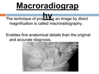
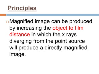
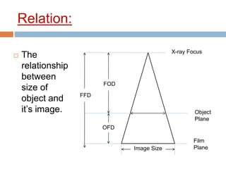
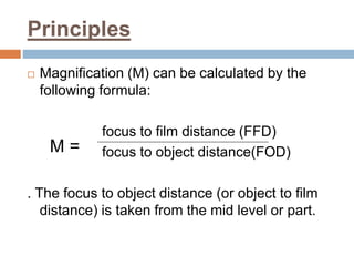
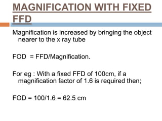
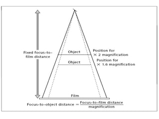
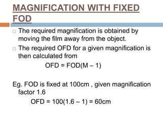
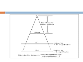
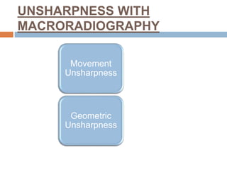
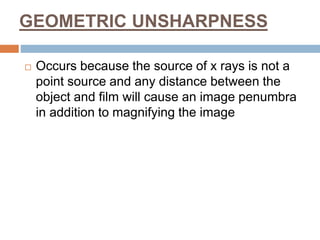
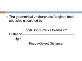
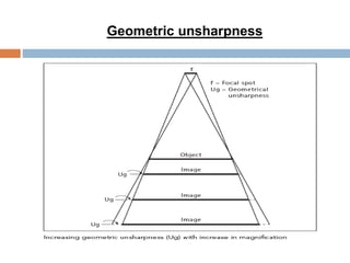
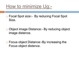
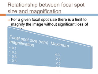
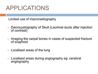
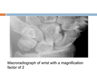
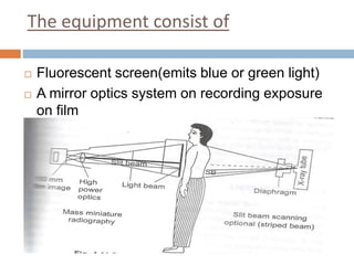
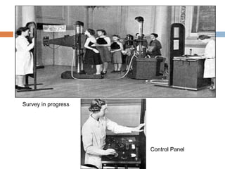
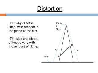
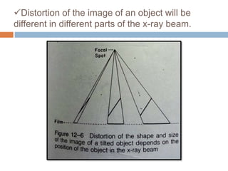
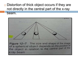
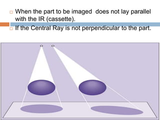
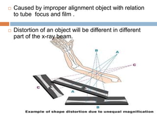
MAGNIFICATION
(MACRORADIOGRAPHY/
MICRORADIOGRAPHY)
DISTORTION
PARTHA JYOTI DAS
MSc MIT
Contents
 Macroradiography
 Principles
 Magnification with fixed FFD
 Magnification with fixed FOD
 Unsharpness with macroradiography
 Applications
 Microradiography
 Mass miniature radiography
 Distortion
 References
The technique of producing an image by direct
magnification is called macroradiography.
Enables fine anatomical details than the original
and accurate diagnosis.
Macroradiograp
hy
Principles
 Magnified image can be produced
by increasing the object to film
distance in which the x rays
diverging from the point source
will produce a directly magnified
image.
Relation:
 The
relationship
between
size of
object and
it’s image.
FFD
FOD
OFD
Image Size
X-ray Focus
Film
Plane
Object
Plane
Principles
 Magnification (M) can be calculated by the
following formula:
focus to film distance (FFD)
focus to object distance(FOD)
. The focus to object distance (or object to film
distance) is taken from the mid level or part.
M =
MAGNIFICATION WITH FIXED
FFD
Magnification is increased by bringing the object
nearer to the x ray tube
FOD = FFD/Magnification.
For eg : With a fixed FFD of 100cm, if a
magnification factor of 1.6 is required then;
FOD = 100/1.6 = 62.5 cm
MAGNIFICATION WITH FIXED
FOD
 The required magnification is obtained by
moving the film away from the object.
 The required OFD for a given magnification is
then calculated from
OFD = FOD(M – 1)
Eg. FOD is fixed at 100cm , given magnification
factor 1.6
OFD = 100(1.6 – 1) = 60cm
UNSHARPNESS WITH
MACRORADIOGRAPHY
Movement
Unsharpness
Geometric
Unsharpness
MOVEMENT UNSHARPNESS
 Direct magnification by increased object to
film distance can be carried out if there is
complete immobilization of the patient
 Any movement due to lack of immobilization or
involuntary movement will be magnified on the
radiograph due to increased OFD
Movement
unsharpness
Some steps
 Use of immobilization devices, e.g. supports,
binders,sandbags and pads.
 Instructions should be given to the patient to
remain still.
GEOMETRIC UNSHARPNESS
 Occurs because the source of x rays is not a
point source and any distance between the
object and film will cause an image penumbra
in addition to magnifying the image
 The geometrical unsharpness for given focal
spot size calculated by
Focal Spot Size x Object-Film
Distance
Ug =
Focus-Object Distance
Geometric unsharpness
How to minimize Ug:-
 Focal Spot size:- By reducing Focal Spot
Size.
 Object image Distance:- By reducing object
image distence.
 Focus object Distance:-By increasing the
Focus object distence.
Relationship between focal spot
size and magnification
 For a given focal spot size there is a limit to
magnify the image without significant loss of
details.
APPLICATIONS
Limited use of macroradiography
 Dacrocystography of Skull (Lacrimal ducts after injection
of contrast)
 Imaging the carpal bones in cases of suspected fracture
of scaphoid
 Localised areas of the lung
 Localised areas during angiography eg: cerebral
angiography
Macroradiograph of wrist with a magnification
factor of 2
Microradiography
 An imaging technique used to examine
very small objects or minute details, often
with the use of high-voltages, very small
focal spot size, and an ultrafine film
emulsion.
Ultrafine Emulsion film
 Photo print made by these films performs rich
sharpness, high definition, strong scratch
resistance, as well as long lasting by pigment
Microradiography
 It is also called as chest fluoroscopy.
 The image on a fluorescent screen is
photographed on a small film. Screen and film
are separated and the image is focused on the
film by a camera lens
 Miniature radiographs (70mmx70mm or
100mmx100mm roll or cut films were used).
 A permanent record is possible.
Mass Miniature Radiography(MMR)
 In order to control tuberculosis, medical research
council, London appointed their Committee on
Tuberculosis in 1941.
 The detection of symptomless or latent pulmonary
tuberculosis by mass radiography had been the
subject of much careful investigation.
 An excellent instrument was designed by the
council for this purpose and in 1943 the Ministry of
Health announced that a limited number of mobile
miniature radiography sets.
The equipment consist of
 Fluorescent screen(emits blue or green light)
 A mirror optics system on recording exposure
on film
Survey in progress
Control Panel
Apparatus for MMR
1.Power unit:- High tension unit
 Four valve rectification
 An output of from 100 to 400mA
 A maximum kilovoltage of 100 kVp and 91 kVp
respectively
2. X-ray Tube
 The rotating anode X-ray tube
 Dual focus, Focal-spot sizes are 1mm and
2mm square.
 An optical centring device.
 Adjustable diaphragm
3.Fluorescent Screen and Grid:
 16 by 16 inches fluorescent screen
 Covered by a sheet of protective lead glass.
 Yellow-blue or green type of screen
 A stationary grid is also present which
reduces scatter
4.The Camera.:
 An electrically operated camera is linked with the
X-ray exposure switch.
 Lead glass protection is present on the camera side of
screen
5.The lens: a number of different lenses
Developing MMR films
 Special tanks meant for roll films on a spiral frame
Development time was 7min at 68 degree F
Viewing of MMR FILMS
 Projector for viewing miniature radiographs
Magnifying glasses
DISTORTION
DISTORTION
 Misrepresentation of the true size and
shape of an object is called distortion.
 Distortion results from unequal
magnification of different parts of the
same object.
Foca
l
Spot
Film
•The object AB is
tilted with respect to
the plane of the film.
•The size and shape
of image vary with
the amount of tilting.
Distortion
A
B
A B
Distortion of the image of an object will be
different in different parts of the x-ray beam.
 Distortion of thick object occurs if they are
not directly in the central part of the x-ray
beam.
 When the part to be imaged does not lay parallel
with the IR (cassette).
 If the Central Ray is not perpendicular to the part.
 Caused by improper alignment object with relation
to tube focus and film .
 Distortion of an object will be different in different
part of the x-ray beam.
Elongated Foreshortened Normal
 GOOD RADIOGRAPHS
 MAKES EVERYONE HAPPY
REFERENCES
 CHESNEY’S RADIOGRAPHIC IMAGING, 6TH EDITION
 JOHN BALL, TONY PRICE HDCR
 CLARK’S POSITIONING IN RADIOGRAPHY, 12TH
EDITION
 A. Stewart Whitley Charles Sloane Graham Hoadley Adrian D. Moore
Chrissie W. Alsop
.
Thank You

Magnification(macro and micro radiography), distortion

  • 1.
  • 2.
    Contents  Macroradiography  Principles Magnification with fixed FFD  Magnification with fixed FOD  Unsharpness with macroradiography  Applications  Microradiography  Mass miniature radiography  Distortion  References
  • 3.
    The technique ofproducing an image by direct magnification is called macroradiography. Enables fine anatomical details than the original and accurate diagnosis. Macroradiograp hy
  • 4.
    Principles  Magnified imagecan be produced by increasing the object to film distance in which the x rays diverging from the point source will produce a directly magnified image.
  • 5.
    Relation:  The relationship between size of objectand it’s image. FFD FOD OFD Image Size X-ray Focus Film Plane Object Plane
  • 6.
    Principles  Magnification (M)can be calculated by the following formula: focus to film distance (FFD) focus to object distance(FOD) . The focus to object distance (or object to film distance) is taken from the mid level or part. M =
  • 7.
    MAGNIFICATION WITH FIXED FFD Magnificationis increased by bringing the object nearer to the x ray tube FOD = FFD/Magnification. For eg : With a fixed FFD of 100cm, if a magnification factor of 1.6 is required then; FOD = 100/1.6 = 62.5 cm
  • 9.
    MAGNIFICATION WITH FIXED FOD The required magnification is obtained by moving the film away from the object.  The required OFD for a given magnification is then calculated from OFD = FOD(M – 1) Eg. FOD is fixed at 100cm , given magnification factor 1.6 OFD = 100(1.6 – 1) = 60cm
  • 11.
  • 12.
    MOVEMENT UNSHARPNESS  Directmagnification by increased object to film distance can be carried out if there is complete immobilization of the patient  Any movement due to lack of immobilization or involuntary movement will be magnified on the radiograph due to increased OFD
  • 13.
  • 14.
    Some steps  Useof immobilization devices, e.g. supports, binders,sandbags and pads.  Instructions should be given to the patient to remain still.
  • 15.
    GEOMETRIC UNSHARPNESS  Occursbecause the source of x rays is not a point source and any distance between the object and film will cause an image penumbra in addition to magnifying the image
  • 16.
     The geometricalunsharpness for given focal spot size calculated by Focal Spot Size x Object-Film Distance Ug = Focus-Object Distance
  • 17.
  • 18.
    How to minimizeUg:-  Focal Spot size:- By reducing Focal Spot Size.  Object image Distance:- By reducing object image distence.  Focus object Distance:-By increasing the Focus object distence.
  • 19.
    Relationship between focalspot size and magnification  For a given focal spot size there is a limit to magnify the image without significant loss of details.
  • 20.
    APPLICATIONS Limited use ofmacroradiography  Dacrocystography of Skull (Lacrimal ducts after injection of contrast)  Imaging the carpal bones in cases of suspected fracture of scaphoid  Localised areas of the lung  Localised areas during angiography eg: cerebral angiography
  • 21.
    Macroradiograph of wristwith a magnification factor of 2
  • 22.
    Microradiography  An imagingtechnique used to examine very small objects or minute details, often with the use of high-voltages, very small focal spot size, and an ultrafine film emulsion.
  • 23.
    Ultrafine Emulsion film Photo print made by these films performs rich sharpness, high definition, strong scratch resistance, as well as long lasting by pigment
  • 24.
    Microradiography  It isalso called as chest fluoroscopy.  The image on a fluorescent screen is photographed on a small film. Screen and film are separated and the image is focused on the film by a camera lens  Miniature radiographs (70mmx70mm or 100mmx100mm roll or cut films were used).  A permanent record is possible.
  • 25.
    Mass Miniature Radiography(MMR) In order to control tuberculosis, medical research council, London appointed their Committee on Tuberculosis in 1941.  The detection of symptomless or latent pulmonary tuberculosis by mass radiography had been the subject of much careful investigation.  An excellent instrument was designed by the council for this purpose and in 1943 the Ministry of Health announced that a limited number of mobile miniature radiography sets.
  • 26.
    The equipment consistof  Fluorescent screen(emits blue or green light)  A mirror optics system on recording exposure on film
  • 27.
  • 28.
    Apparatus for MMR 1.Powerunit:- High tension unit  Four valve rectification  An output of from 100 to 400mA  A maximum kilovoltage of 100 kVp and 91 kVp respectively
  • 29.
    2. X-ray Tube The rotating anode X-ray tube  Dual focus, Focal-spot sizes are 1mm and 2mm square.  An optical centring device.  Adjustable diaphragm
  • 30.
    3.Fluorescent Screen andGrid:  16 by 16 inches fluorescent screen  Covered by a sheet of protective lead glass.  Yellow-blue or green type of screen  A stationary grid is also present which reduces scatter 4.The Camera.:  An electrically operated camera is linked with the X-ray exposure switch.  Lead glass protection is present on the camera side of screen 5.The lens: a number of different lenses
  • 31.
    Developing MMR films Special tanks meant for roll films on a spiral frame Development time was 7min at 68 degree F
  • 33.
    Viewing of MMRFILMS  Projector for viewing miniature radiographs Magnifying glasses
  • 34.
  • 35.
    DISTORTION  Misrepresentation ofthe true size and shape of an object is called distortion.  Distortion results from unequal magnification of different parts of the same object.
  • 36.
    Foca l Spot Film •The object ABis tilted with respect to the plane of the film. •The size and shape of image vary with the amount of tilting. Distortion A B A B
  • 37.
    Distortion of theimage of an object will be different in different parts of the x-ray beam.
  • 38.
     Distortion ofthick object occurs if they are not directly in the central part of the x-ray beam.
  • 39.
     When thepart to be imaged does not lay parallel with the IR (cassette).  If the Central Ray is not perpendicular to the part.
  • 40.
     Caused byimproper alignment object with relation to tube focus and film .  Distortion of an object will be different in different part of the x-ray beam.
  • 41.
  • 42.
     GOOD RADIOGRAPHS MAKES EVERYONE HAPPY
  • 43.
    REFERENCES  CHESNEY’S RADIOGRAPHICIMAGING, 6TH EDITION  JOHN BALL, TONY PRICE HDCR  CLARK’S POSITIONING IN RADIOGRAPHY, 12TH EDITION  A. Stewart Whitley Charles Sloane Graham Hoadley Adrian D. Moore Chrissie W. Alsop .
  • 44.