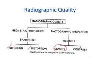
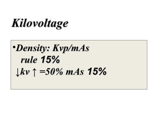
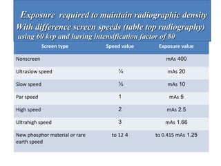
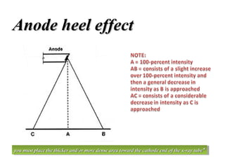
Radiographic Quality
DENSITY (1)
• What exactly is meant by term radiographic
density?
• Radiographic density referred to as the overall
blackening of the film. Density is dependent
on amount of radiation received by the film.
• It is not the technologist’s purposes to
produce an overall black film.
• Technologist is concerned with what is termed
proper density.
(DENSITY (2
• A radiographic image that possesses proper
density provides suitable visualization of all of
the structures of interest.
• Any variance from this value of density is
detrimental to radiographic quality.
• Insufficient density, degrading image quality
as excessive density –in fact, perhaps more so.
Schematic drawing showing
differential
absorption of x–rays by the
tissues of the
body in conventional
radiography. From most to
least radiodense these are (1)
bone or calcium; (2) all soft
tissues and liquids (muscle,
blood, brain, heart, liver,
urine, etc.) except (3) fat; (4)
air or other gases.
DENSITY
?Influencing factors
?Controlling factors
I
FACTORS THAT INFLUENCE and CONTROL
VISIBLE RECORDED DETAIL
Factors that influence visible recorded detail
???What are they
Patient factors
Tissue thickness
Physique
Age
Development
Pathology –additive and destructive
(Tissue opacity (density
Density control factors
((Technique (mA; s; kV; distance -Technique (mA; s; kV; distance
Receptor quantum efficiency

--

Image processing
-Image processing
Anode heel effect-Anode heel effect
Orthopedic casts-Orthopedic casts
Filtrtion-Filtrtion
To increase density
mAs increase required 30%
•A minimal change of 30% is
necessary to produce noticeable
difference in radiographic
density.
Kilovoltage
•Density: Kvp/mAs
rule 15%
↓kv ↑ =50% mAs 15%
A “step in time”
•Abdomen: old 200mAx0.5 s =100 mAs
new 200 mAx0.6 s= 120 mAs

• Elbow:

old 100mAx 0.1 s=10 mAs

new 100mAx0.13.3 s= 13.3 mAs
Distance - Inverse Square Law

• intensity of radiation falling on flat
surface from point source is
inversely proportional to square of
distance from point source

Intensity α 1/d2

– if distance 2X, intensity drops by 4X

• Assumptions
– point source
– no attenuation

• Cause
– increase in exposure area with
distance

d
Intensifying screen
Intensifying screen
Screen intensification factor
Intensification factor formula
=intensification factor

exposure without screens
_____________________
Exposure with screens

Screen intensification factor
••At 50 kv the intensification factor is 60
At 50 kv the intensification factor is 60
••At 60 kv the intensification factor is 80
At 60 kv the intensification factor is 80
••At 70 kv the intensification factor is 100
At 70 kv the intensification factor is 100
Intensifying screen speeds and exposures
Screen type

Speed value

Exposure value

(Ultraslow speed (detail

1/4

times par 4

Slow speed

1/2

times par 2

(Par speed (standard

1

1

High speed

2

times par½

Ultrahigh speed

3

times par 1/3

t0 12 4

to 1/12 times par¼

New phosphor material
and rare earth screens
peed*

Screen speed depends upon the type phosphor used, and the type *
and speed of the film it is used with
Exposure required to maintain radiographic density
With difference screen speeds (table top radiography)
using 60 kvp and having intensification factor of 80
Screen type

Speed value

Nonscreen

Exposure value
mAs 400

Ultraslow speed

¼

mAs 20

Slow speed

½

mAs 10

Par speed

1

mAs 5

High speed

2

mAs 2.5

Ultrahigh speed

3

mAs 1.66

to 12 4

to 0.415 mAs 1.25

New phosphor material or rare
earth speed
Film processing
•Manual processing →difficult
to control quality.
• Automatic processing→
enable the
technologist to standardize film
.processing
Anode heel effect
•Has an influence on uniformity
of overall density of the image.
•In specific application, you can
employ this effect to advantage*

you must place the thicker and/or more dense area toward the cathode end of the x-ray tube **
you must place the thicker and/or more dense area toward the cathode end of the x-ray tube
Anode heel effect

you must place the thicker and/or more dense area toward the cathode end of the x-ray tube **
you must place the thicker and/or more dense area toward the cathode end of the x-ray tube
Orthopedic casts
•Orthopedic casts adds both
thickness and opacity to the part
•Remember double the mAs for
increased part thickness;
increased the kvp by 10 % for
increased part opacity.
Filtration
•Added filtration above 2.5 mm Al
increase exposure factors to
maintain density.
•Remember; added filtration is
used as a means of reducing
patient exposure to radiation.
Filters should not be removed
during routine examination.
Radiopacity and radiolucency are relative
terms. The central gray squares are all of
.the same density
The left triangle seems lighter than the right one.
.This is only an illusion - they are equal in density
Questions please

Density

  • 1.
  • 2.
    DENSITY (1) • Whatexactly is meant by term radiographic density? • Radiographic density referred to as the overall blackening of the film. Density is dependent on amount of radiation received by the film. • It is not the technologist’s purposes to produce an overall black film. • Technologist is concerned with what is termed proper density.
  • 3.
    (DENSITY (2 • Aradiographic image that possesses proper density provides suitable visualization of all of the structures of interest. • Any variance from this value of density is detrimental to radiographic quality. • Insufficient density, degrading image quality as excessive density –in fact, perhaps more so.
  • 4.
    Schematic drawing showing differential absorptionof x–rays by the tissues of the body in conventional radiography. From most to least radiodense these are (1) bone or calcium; (2) all soft tissues and liquids (muscle, blood, brain, heart, liver, urine, etc.) except (3) fat; (4) air or other gases.
  • 6.
  • 7.
    FACTORS THAT INFLUENCEand CONTROL VISIBLE RECORDED DETAIL Factors that influence visible recorded detail ???What are they Patient factors Tissue thickness Physique Age Development Pathology –additive and destructive (Tissue opacity (density
  • 8.
    Density control factors ((Technique(mA; s; kV; distance -Technique (mA; s; kV; distance Receptor quantum efficiency Receptor quantum efficiency -- Image processing -Image processing Anode heel effect-Anode heel effect Orthopedic casts-Orthopedic casts Filtrtion-Filtrtion
  • 9.
    To increase density mAsincrease required 30% •A minimal change of 30% is necessary to produce noticeable difference in radiographic density.
  • 10.
  • 11.
    A “step intime” •Abdomen: old 200mAx0.5 s =100 mAs new 200 mAx0.6 s= 120 mAs • Elbow: old 100mAx 0.1 s=10 mAs new 100mAx0.13.3 s= 13.3 mAs
  • 12.
    Distance - InverseSquare Law • intensity of radiation falling on flat surface from point source is inversely proportional to square of distance from point source Intensity α 1/d2 – if distance 2X, intensity drops by 4X • Assumptions – point source – no attenuation • Cause – increase in exposure area with distance d
  • 13.
    Intensifying screen Intensifying screen Screenintensification factor Screen intensification factor Intensification factor formula =intensification factor exposure without screens _____________________ Exposure with screens Screen intensification factor Screen intensification factor ••At 50 kv the intensification factor is 60 At 50 kv the intensification factor is 60 ••At 60 kv the intensification factor is 80 At 60 kv the intensification factor is 80 ••At 70 kv the intensification factor is 100 At 70 kv the intensification factor is 100
  • 14.
    Intensifying screen speedsand exposures Intensifying screen speeds and exposures Screen type Speed value Exposure value (Ultraslow speed (detail 1/4 times par 4 Slow speed 1/2 times par 2 (Par speed (standard 1 1 High speed 2 times par½ Ultrahigh speed 3 times par 1/3 t0 12 4 to 1/12 times par¼ New phosphor material and rare earth screens peed* Screen speed depends upon the type phosphor used, and the type * and speed of the film it is used with
  • 15.
    Exposure required tomaintain radiographic density With difference screen speeds (table top radiography) using 60 kvp and having intensification factor of 80 Screen type Speed value Nonscreen Exposure value mAs 400 Ultraslow speed ¼ mAs 20 Slow speed ½ mAs 10 Par speed 1 mAs 5 High speed 2 mAs 2.5 Ultrahigh speed 3 mAs 1.66 to 12 4 to 0.415 mAs 1.25 New phosphor material or rare earth speed
  • 16.
    Film processing •Manual processing→difficult to control quality. • Automatic processing→ enable the technologist to standardize film .processing
  • 17.
    Anode heel effect •Hasan influence on uniformity of overall density of the image. •In specific application, you can employ this effect to advantage* you must place the thicker and/or more dense area toward the cathode end of the x-ray tube ** you must place the thicker and/or more dense area toward the cathode end of the x-ray tube
  • 18.
    Anode heel effect youmust place the thicker and/or more dense area toward the cathode end of the x-ray tube ** you must place the thicker and/or more dense area toward the cathode end of the x-ray tube
  • 19.
    Orthopedic casts •Orthopedic castsadds both thickness and opacity to the part •Remember double the mAs for increased part thickness; increased the kvp by 10 % for increased part opacity.
  • 20.
    Filtration •Added filtration above2.5 mm Al increase exposure factors to maintain density. •Remember; added filtration is used as a means of reducing patient exposure to radiation. Filters should not be removed during routine examination.
  • 21.
    Radiopacity and radiolucencyare relative terms. The central gray squares are all of .the same density
  • 22.
    The left triangleseems lighter than the right one. .This is only an illusion - they are equal in density
  • 23.