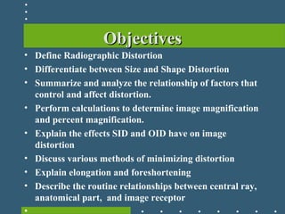
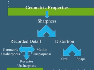
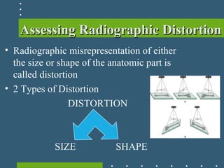
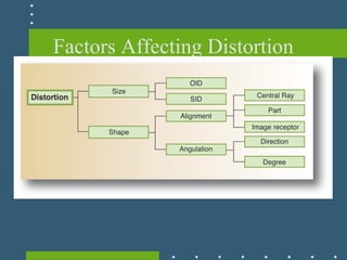
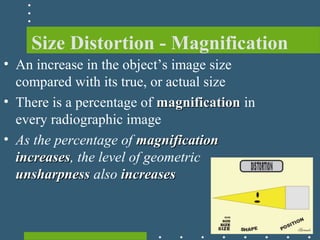
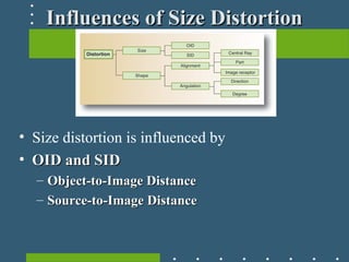
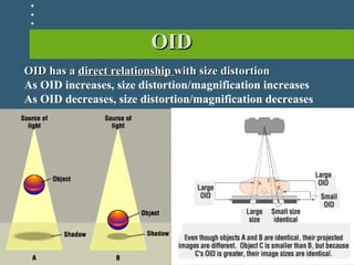
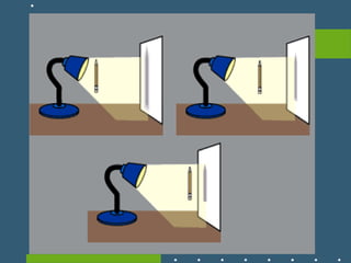
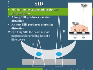
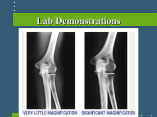
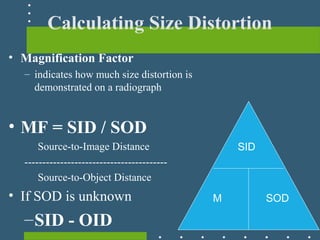
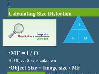
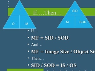
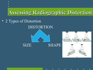
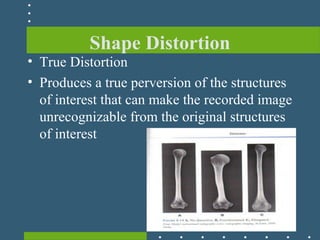
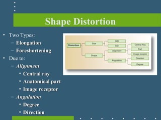
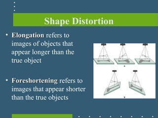
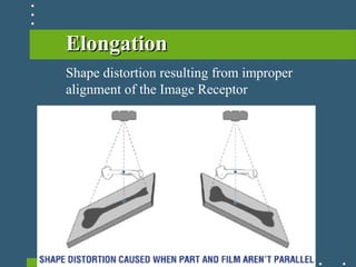
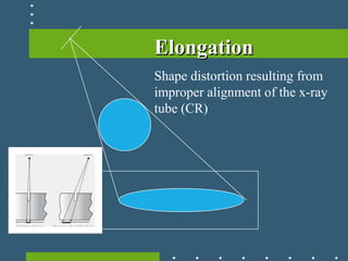
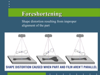
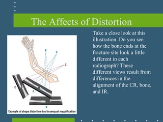
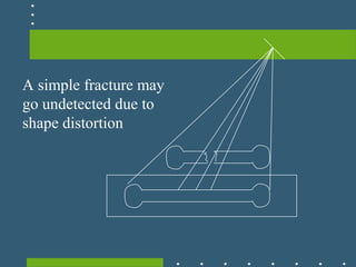
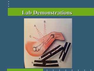
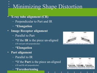
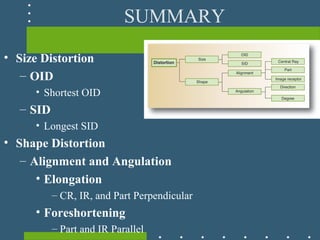
Radiographic DistortionRadiographic Distortion
Principles of Radiographic Imaging
ObjectivesObjectives
• Define Radiographic Distortion
• Differentiate between Size and Shape Distortion
• Summarize and analyze the relationship of factors that
control and affect distortion.
• Perform calculations to determine image magnification
and percent magnification.
• Explain the effects SID and OID have on image
distortion
• Discuss various methods of minimizing distortion
• Explain elongation and foreshortening
• Describe the routine relationships between central ray,
anatomical part, and image receptor
•
Geometric Properties
Sharpness
Recorded Detail Distortion
Size Shape
Receptor
Unsharpness
Geometric
Unsharpness
Motion
Unsharpness
Assessing Radiographic DistortionAssessing Radiographic Distortion
• Radiographic misrepresentation of either
the size or shape of the anatomic part is
called distortion
• 2 Types of Distortion
DISTORTION
SIZE SHAPE
Factors Affecting Distortion
Size Distortion - Magnification
• An increase in the object’s image size
compared with its true, or actual size
• There is a percentage of magnificationmagnification in
every radiographic image
• As the percentage of magnificationmagnification
increasesincreases, the level of geometric
unsharpnessunsharpness also increasesincreases
Influences of Size DistortionInfluences of Size Distortion
• Size distortion is influenced by
• OID and SIDOID and SID
– Object-to-Image DistanceObject-to-Image Distance
– Source-to-Image DistanceSource-to-Image Distance
OIDOID
Shadow
OID has aOID has a direct relationshipdirect relationship with size distortionwith size distortion
As OID increases, size distortion/magnification increases
As OID decreases, size distortion/magnification decreases
A
B
• SID has anSID has an inverse relationshipinverse relationship withwith
size distortionsize distortion
• A long SID produces less size
distortion
• A short SID produces more size
distortion
With a long SID the beam is more
perpendicular creating less of a
divergence
SIDSID
Lab DemonstrationsLab Demonstrations
Interactive ReviewInteractive Review
• Interactive Online Reviews
– Plickers
– Quizstar
– Qzzr
• Group/Team Work
Calculating Size Distortion
• Magnification Factor
– indicates how much size distortion is
demonstrated on a radiograph
• MF = SID / SOD
Source-to-Image Distance
----------------------------------------
Source-to-Object Distance
• If SOD is unknown
–SID - OID
M
SID
SOD
Calculating MF
• Examples
Calculating Size Distortion
•MF = I / O
•If Object Size is unknown
•Object Size = Image size / MF
O
I
M
Calculating MF
• Examples
If….Then…
M
SID
SOD
O
I
M
• If…
• MF = SID / SODMF = SID / SOD
• And…
• MF = Image Size / Object SizMF = Image Size / Object Siz
• Then…
• SID / SOD = IS / OSSID / SOD = IS / OS
Calculating MF
• Examples
Assessing Radiographic DistortionAssessing Radiographic Distortion
• 2 Types of Distortion
DISTORTION
SIZE SHAPE
Shape Distortion
• True Distortion
• Produces a true perversion of the structures
of interest that can make the recorded image
unrecognizable from the original structures
of interest
Shape Distortion
• Two Types:
– ElongationElongation
– ForeshorteningForeshortening
• Due to:
– AlignmentAlignment
• Central rayCentral ray
• Anatomical partAnatomical part
• Image receptorImage receptor
– AngulationAngulation
• DegreeDegree
• DirectionDirection
Shape Distortion
• ElongationElongation refers to
images of objects that
appear longer than the
true object
• ForeshorteningForeshortening refers to
images that appear shorter
than the true objects
ElongationElongation
Shape distortion resulting from improper
alignment of the Image Receptor
ElongationElongation
Shape distortion resulting from
improper alignment of the x-ray
tube (CR)
ForeshorteningForeshortening
Shape distortion resulting from improper
alignment of the part
The Affects of Distortion
Take a close look at this
illustration. Do you see
how the bone ends at the
fracture site look a little
different in each
radiograph? These
different views result from
differences in the
alignment of the CR, bone,
and IR.
A simple fracture may
go undetected due to
shape distortion
Lab DemonstrationsLab Demonstrations
Minimizing Shape Distortion
• X-ray tube alignment (CR)
– Perpendicular to Part and IR
– *Elongation
• Image Receptor alignment
– Parallel to Part
– *If the IR is the piece un-aligned
– (CR and part still perpendicular)
– *Elongation
• Part alignment
– Parallel to IR
– *If the Part is the piece un-aligned
– (CR and IR still perpendicular)
– *Foreshortening
Interactive ReviewInteractive Review
• Interactive Online Reviews
– Plickers
– Quizstar
– Qzzr
• Group/Team Work
SUMMARY
• Size Distortion
– OID
• Shortest OID
– SID
• Longest SID
• Shape Distortion
– Alignment and Angulation
• Elongation
– CR, IR, and Part Perpendicular
• Foreshortening
– Part and IR Parallel

Geometric Properties Distortion

  • 1.
  • 2.
    ObjectivesObjectives • Define RadiographicDistortion • Differentiate between Size and Shape Distortion • Summarize and analyze the relationship of factors that control and affect distortion. • Perform calculations to determine image magnification and percent magnification. • Explain the effects SID and OID have on image distortion • Discuss various methods of minimizing distortion • Explain elongation and foreshortening • Describe the routine relationships between central ray, anatomical part, and image receptor •
  • 3.
    Geometric Properties Sharpness Recorded DetailDistortion Size Shape Receptor Unsharpness Geometric Unsharpness Motion Unsharpness
  • 4.
    Assessing Radiographic DistortionAssessingRadiographic Distortion • Radiographic misrepresentation of either the size or shape of the anatomic part is called distortion • 2 Types of Distortion DISTORTION SIZE SHAPE
  • 5.
  • 6.
    Size Distortion -Magnification • An increase in the object’s image size compared with its true, or actual size • There is a percentage of magnificationmagnification in every radiographic image • As the percentage of magnificationmagnification increasesincreases, the level of geometric unsharpnessunsharpness also increasesincreases
  • 7.
    Influences of SizeDistortionInfluences of Size Distortion • Size distortion is influenced by • OID and SIDOID and SID – Object-to-Image DistanceObject-to-Image Distance – Source-to-Image DistanceSource-to-Image Distance
  • 8.
    OIDOID Shadow OID has aOIDhas a direct relationshipdirect relationship with size distortionwith size distortion As OID increases, size distortion/magnification increases As OID decreases, size distortion/magnification decreases
  • 10.
    A B • SID hasanSID has an inverse relationshipinverse relationship withwith size distortionsize distortion • A long SID produces less size distortion • A short SID produces more size distortion With a long SID the beam is more perpendicular creating less of a divergence SIDSID
  • 11.
  • 12.
    Interactive ReviewInteractive Review •Interactive Online Reviews – Plickers – Quizstar – Qzzr • Group/Team Work
  • 13.
    Calculating Size Distortion •Magnification Factor – indicates how much size distortion is demonstrated on a radiograph • MF = SID / SOD Source-to-Image Distance ---------------------------------------- Source-to-Object Distance • If SOD is unknown –SID - OID M SID SOD
  • 14.
  • 15.
    Calculating Size Distortion •MF= I / O •If Object Size is unknown •Object Size = Image size / MF O I M
  • 16.
  • 17.
    If….Then… M SID SOD O I M • If… • MF= SID / SODMF = SID / SOD • And… • MF = Image Size / Object SizMF = Image Size / Object Siz • Then… • SID / SOD = IS / OSSID / SOD = IS / OS
  • 18.
  • 19.
    Assessing Radiographic DistortionAssessingRadiographic Distortion • 2 Types of Distortion DISTORTION SIZE SHAPE
  • 20.
    Shape Distortion • TrueDistortion • Produces a true perversion of the structures of interest that can make the recorded image unrecognizable from the original structures of interest
  • 21.
    Shape Distortion • TwoTypes: – ElongationElongation – ForeshorteningForeshortening • Due to: – AlignmentAlignment • Central rayCentral ray • Anatomical partAnatomical part • Image receptorImage receptor – AngulationAngulation • DegreeDegree • DirectionDirection
  • 22.
    Shape Distortion • ElongationElongationrefers to images of objects that appear longer than the true object • ForeshorteningForeshortening refers to images that appear shorter than the true objects
  • 23.
    ElongationElongation Shape distortion resultingfrom improper alignment of the Image Receptor
  • 24.
    ElongationElongation Shape distortion resultingfrom improper alignment of the x-ray tube (CR)
  • 25.
  • 26.
    The Affects ofDistortion Take a close look at this illustration. Do you see how the bone ends at the fracture site look a little different in each radiograph? These different views result from differences in the alignment of the CR, bone, and IR.
  • 27.
    A simple fracturemay go undetected due to shape distortion
  • 28.
  • 29.
    Minimizing Shape Distortion •X-ray tube alignment (CR) – Perpendicular to Part and IR – *Elongation • Image Receptor alignment – Parallel to Part – *If the IR is the piece un-aligned – (CR and part still perpendicular) – *Elongation • Part alignment – Parallel to IR – *If the Part is the piece un-aligned – (CR and IR still perpendicular) – *Foreshortening
  • 30.
    Interactive ReviewInteractive Review •Interactive Online Reviews – Plickers – Quizstar – Qzzr • Group/Team Work
  • 31.
    SUMMARY • Size Distortion –OID • Shortest OID – SID • Longest SID • Shape Distortion – Alignment and Angulation • Elongation – CR, IR, and Part Perpendicular • Foreshortening – Part and IR Parallel