Downloaded 206 times
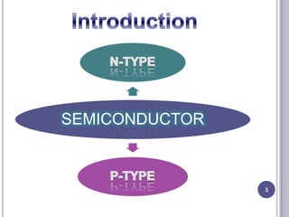
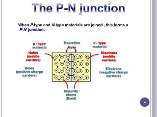
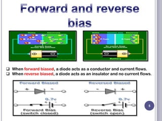


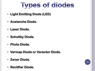

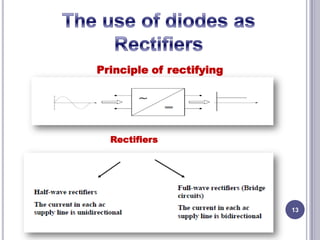
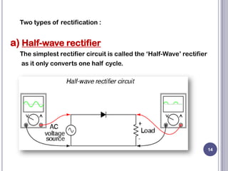
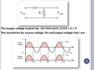


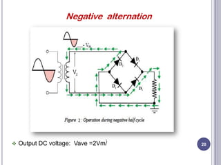

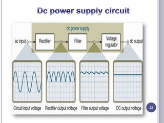


This document discusses diodes and their applications. It begins with an introduction to diodes, including what a diode is, the P-N junction, and diode characteristics when forward and reverse biased. It then covers types of diodes like LEDs, Zener diodes, and more. Applications discussed include logic gates, temperature measurement, and power conversion. The document focuses on rectifiers, explaining half-wave and full-wave rectification and how diodes are used to convert AC to DC in power supplies. Circuit diagrams are provided to illustrate the principles and components of half-wave and full-wave rectifiers, including the addition of a capacitor filter.