Downloaded 903 times
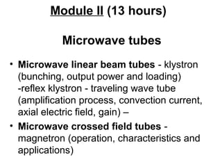
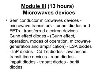
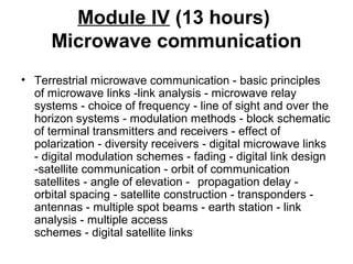

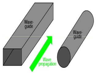
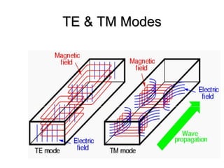
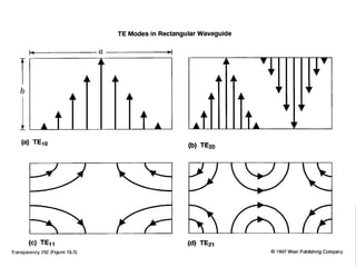
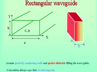


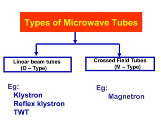
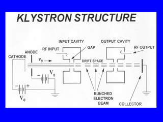
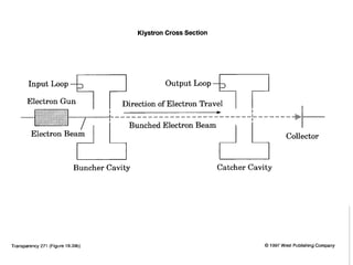

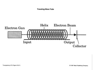

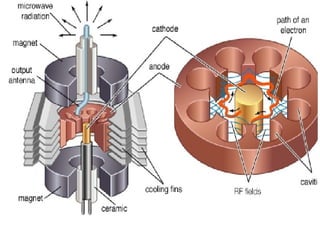


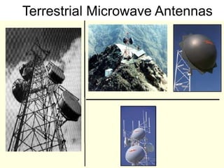
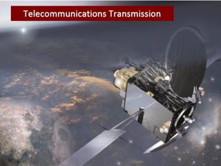
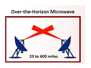
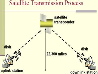


The document provides an overview of microwave devices and communication, covering principles of microwave engineering, microwave tubes, semiconductor microwave devices, and both terrestrial and satellite microwave communication systems. It includes objectives, module breakdowns, principles of various technologies, and components essential for understanding microwave communication. Key topics include waveguide transmission, microwave tubes like klystrons and magnetrons, and various forms of microwave communication links.


