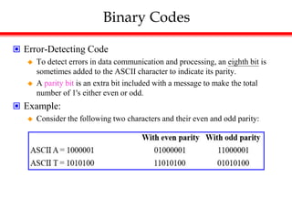
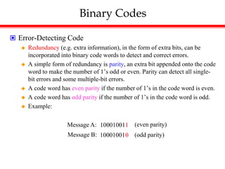
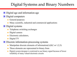
Digital Systems and Binary Numbers
- Digital systems manipulate discrete elements of information represented in binary form.
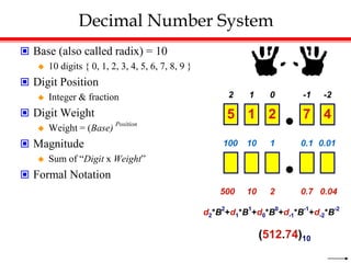
- The binary number system uses only two digits, 0 and 1, with place values that are powers of two.
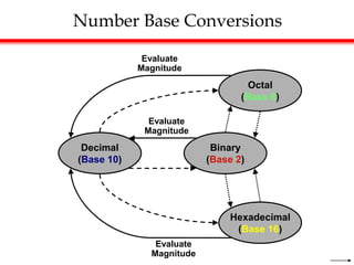
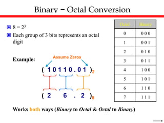
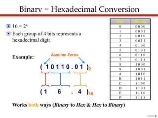
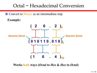
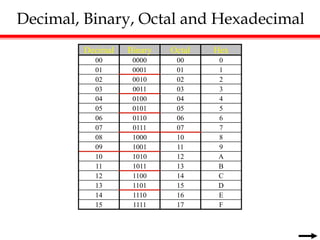
- Conversions can be made between decimal, binary, octal, and hexadecimal number systems through arithmetic operations and grouping bits.
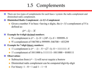
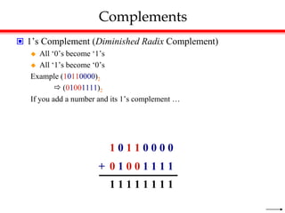
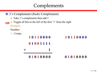
![Complements
Radix Complement
Example: Base-10
Example: Base-2
The r's complement of an n-digit number N in base r is defined as
rn – N for N ≠ 0 and as 0 for N = 0. Comparing with the (r 1) 's
complement, we note that the r's complement is obtained by adding 1
to the (r 1) 's complement, since rn – N = [(rn 1) – N] + 1.
The 10's complement of 012398 is 987602
The 10's complement of 246700 is 753300
The 2's complement of 1101100 is 0010100
The 2's complement of 0110111 is 1001001](https://image.slidesharecdn.com/chapter1digitalsystemsandbinarynumbers-230506085614-187915be/85/Chapter-1-Digital-Systems-and-Binary-Numbers-ppt-30-320.jpg)