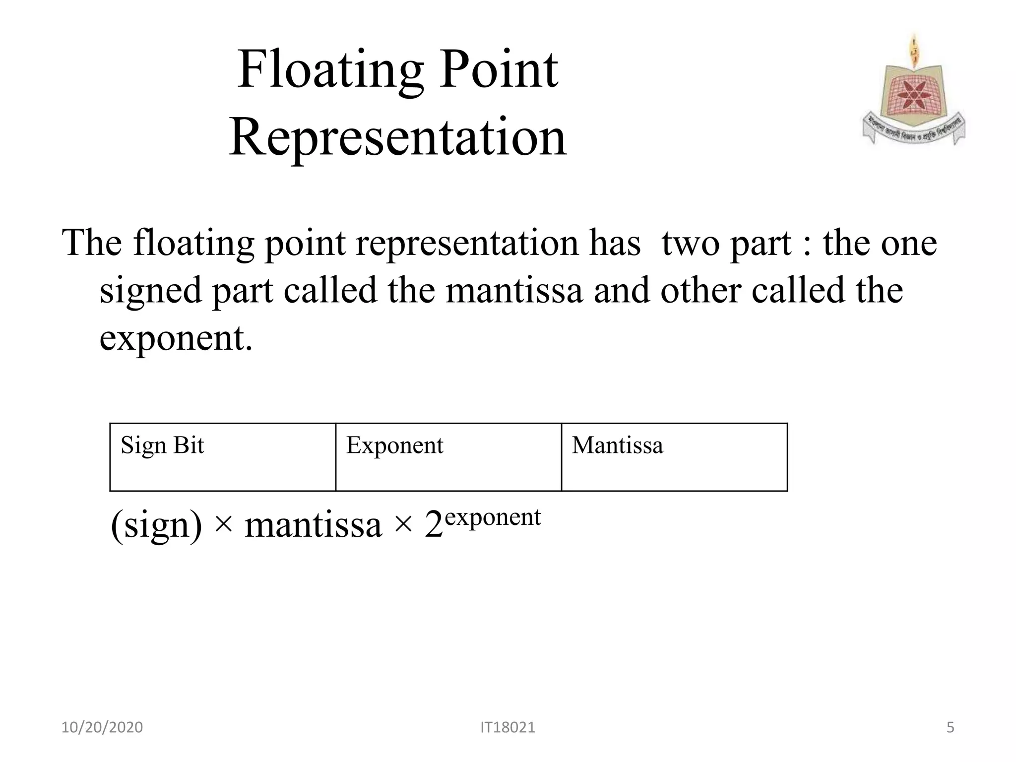
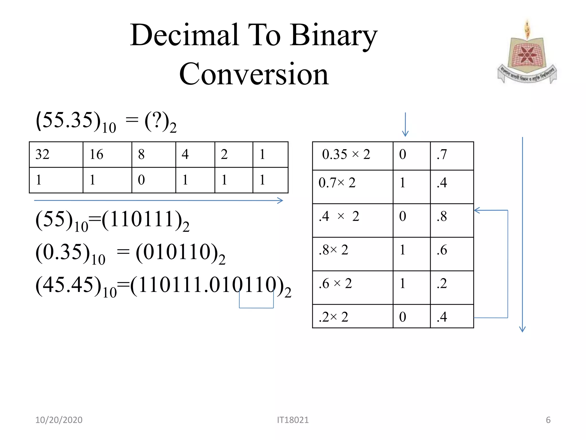
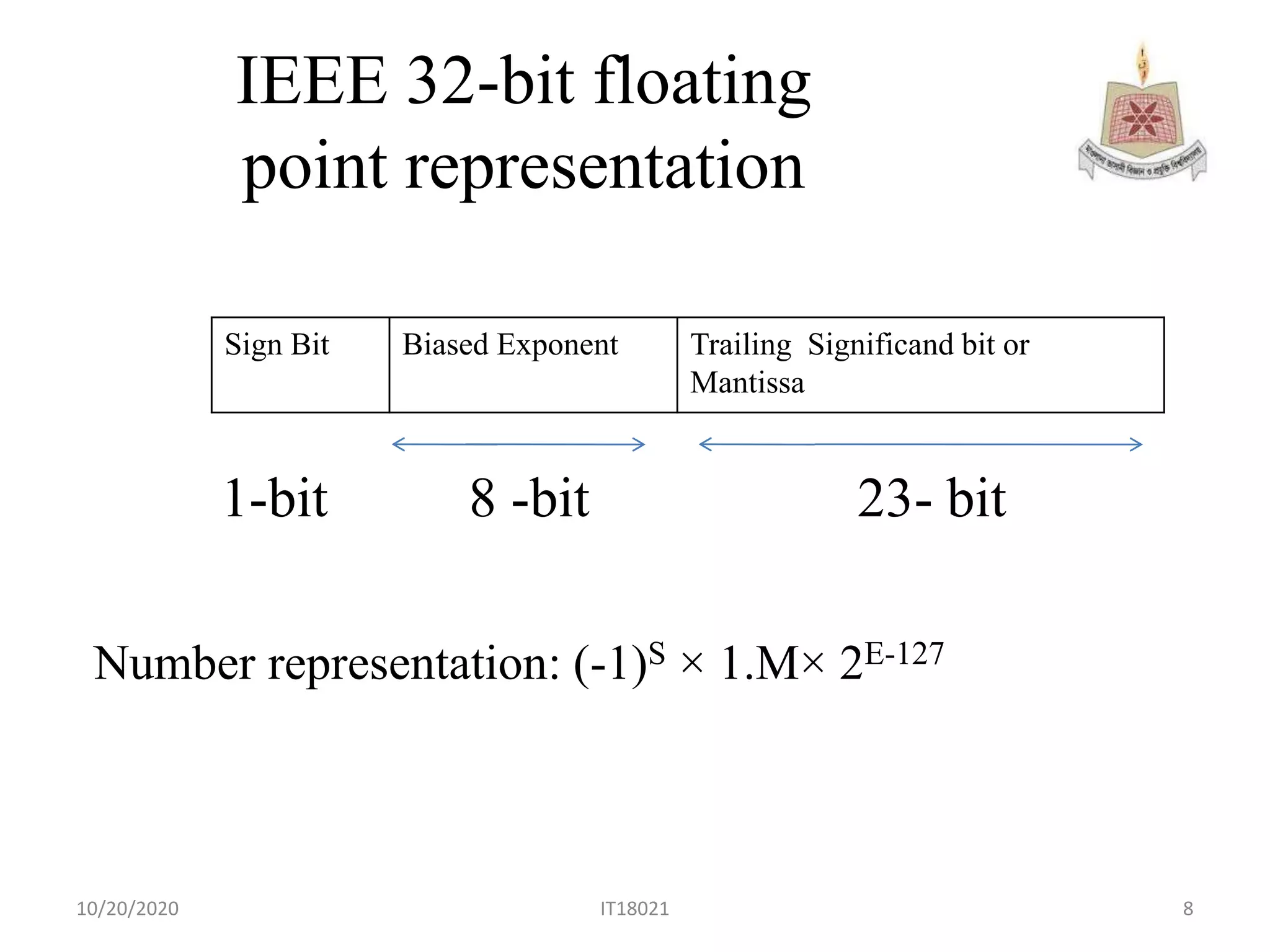
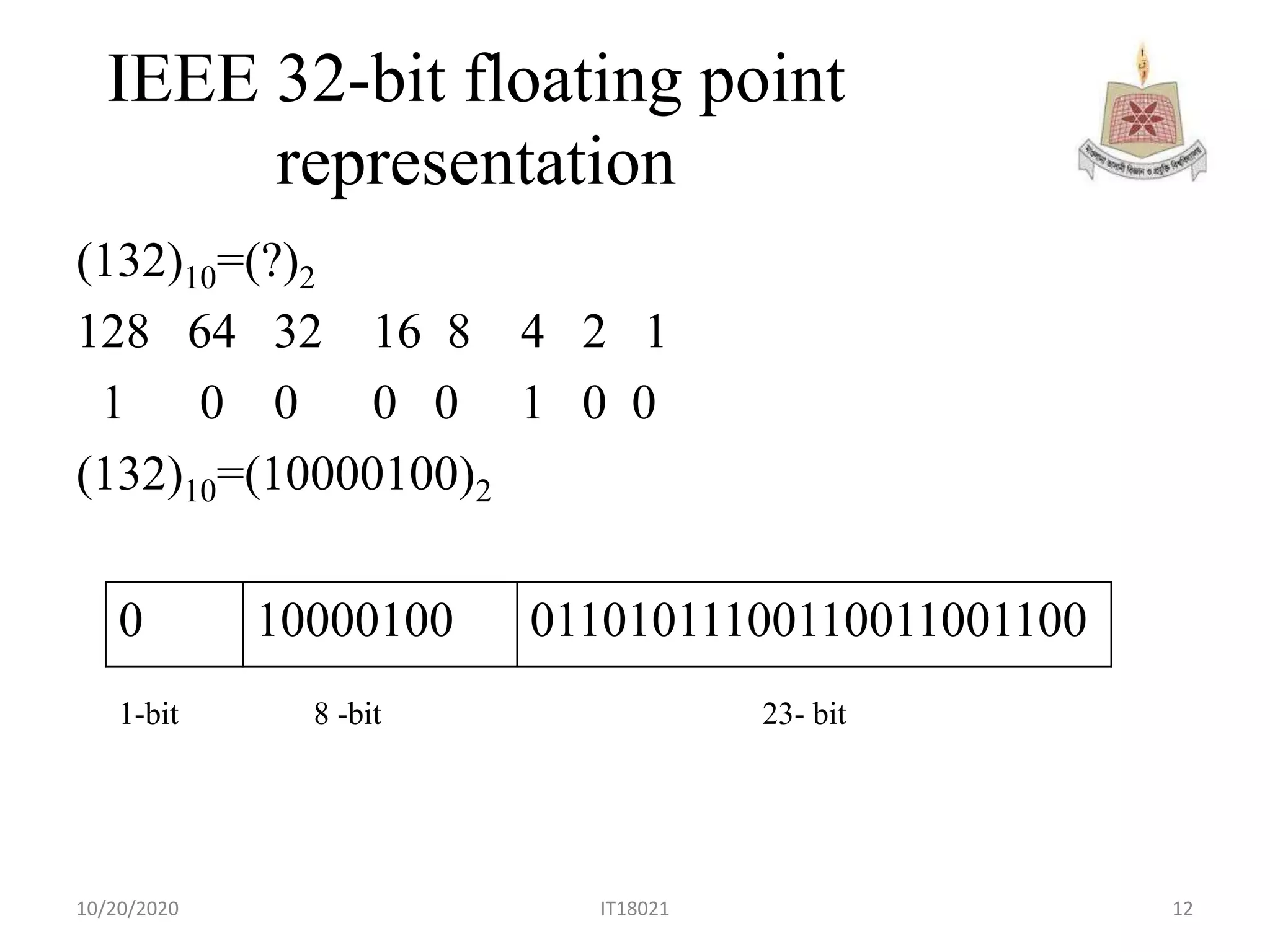
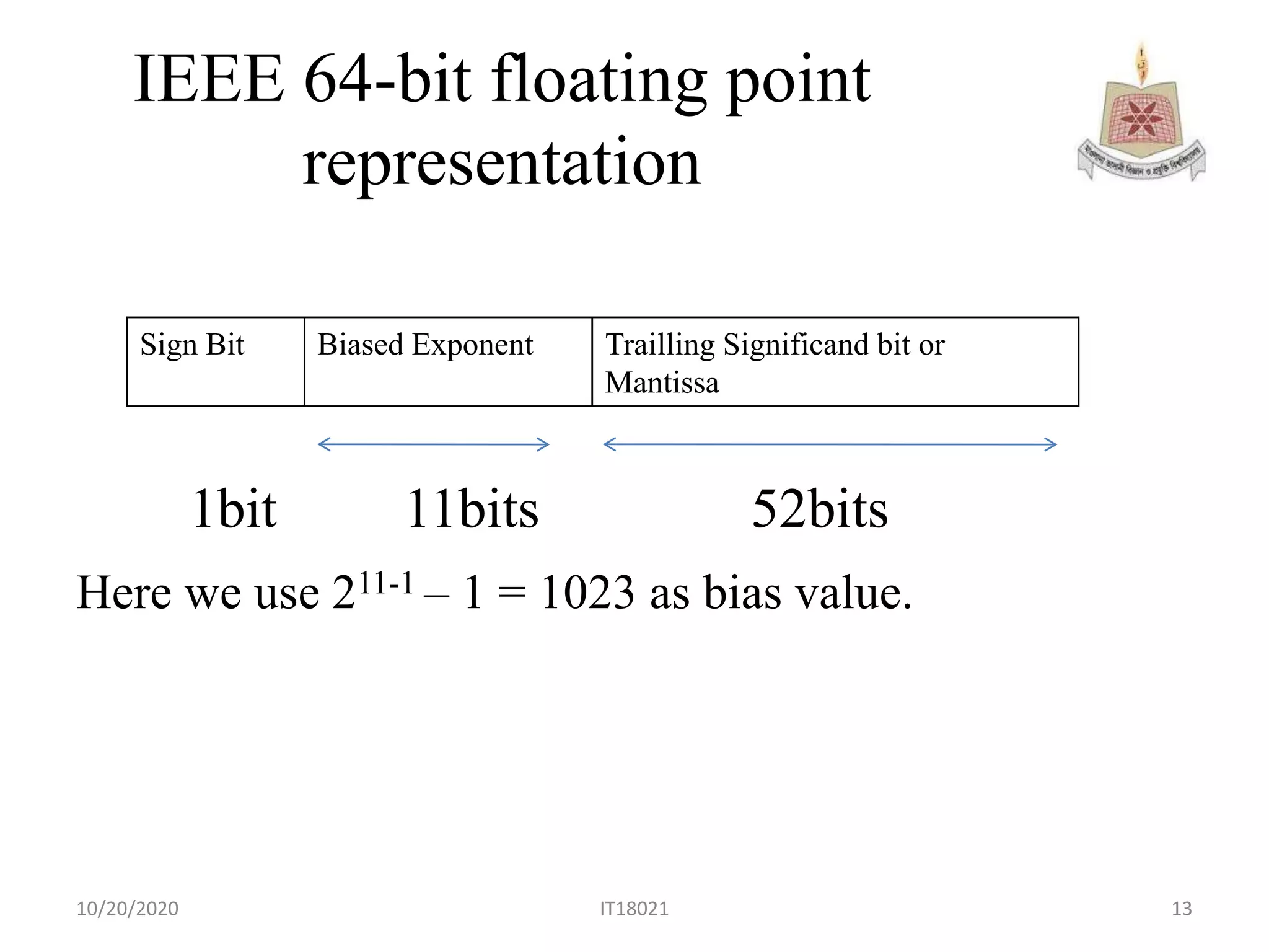
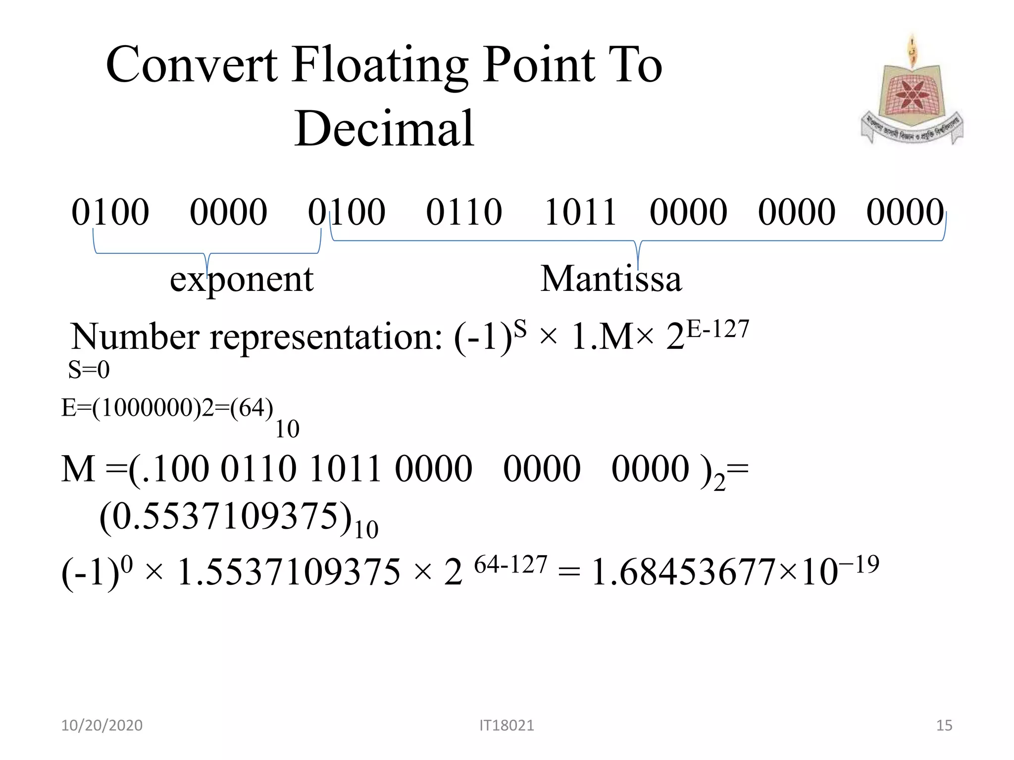
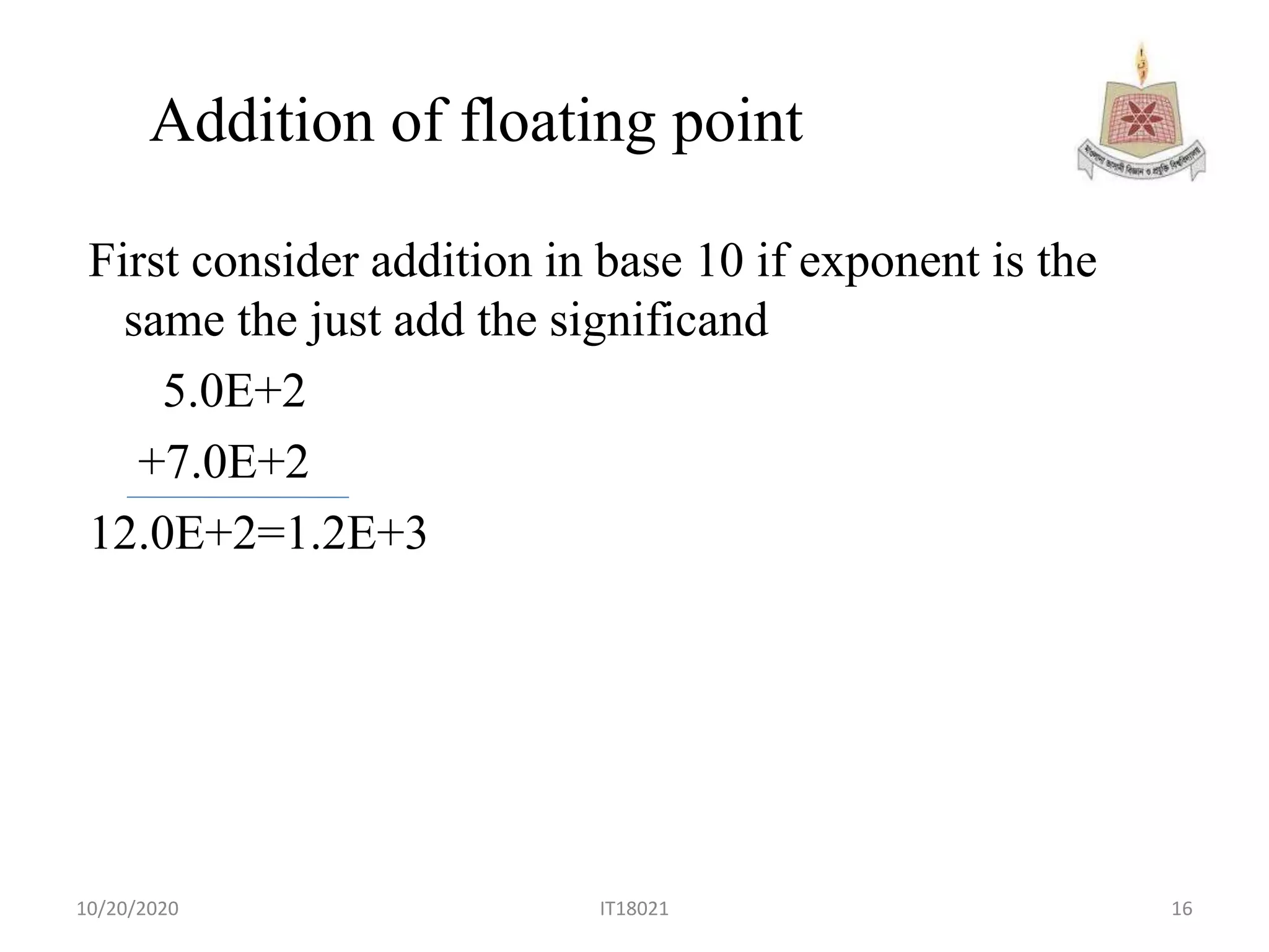
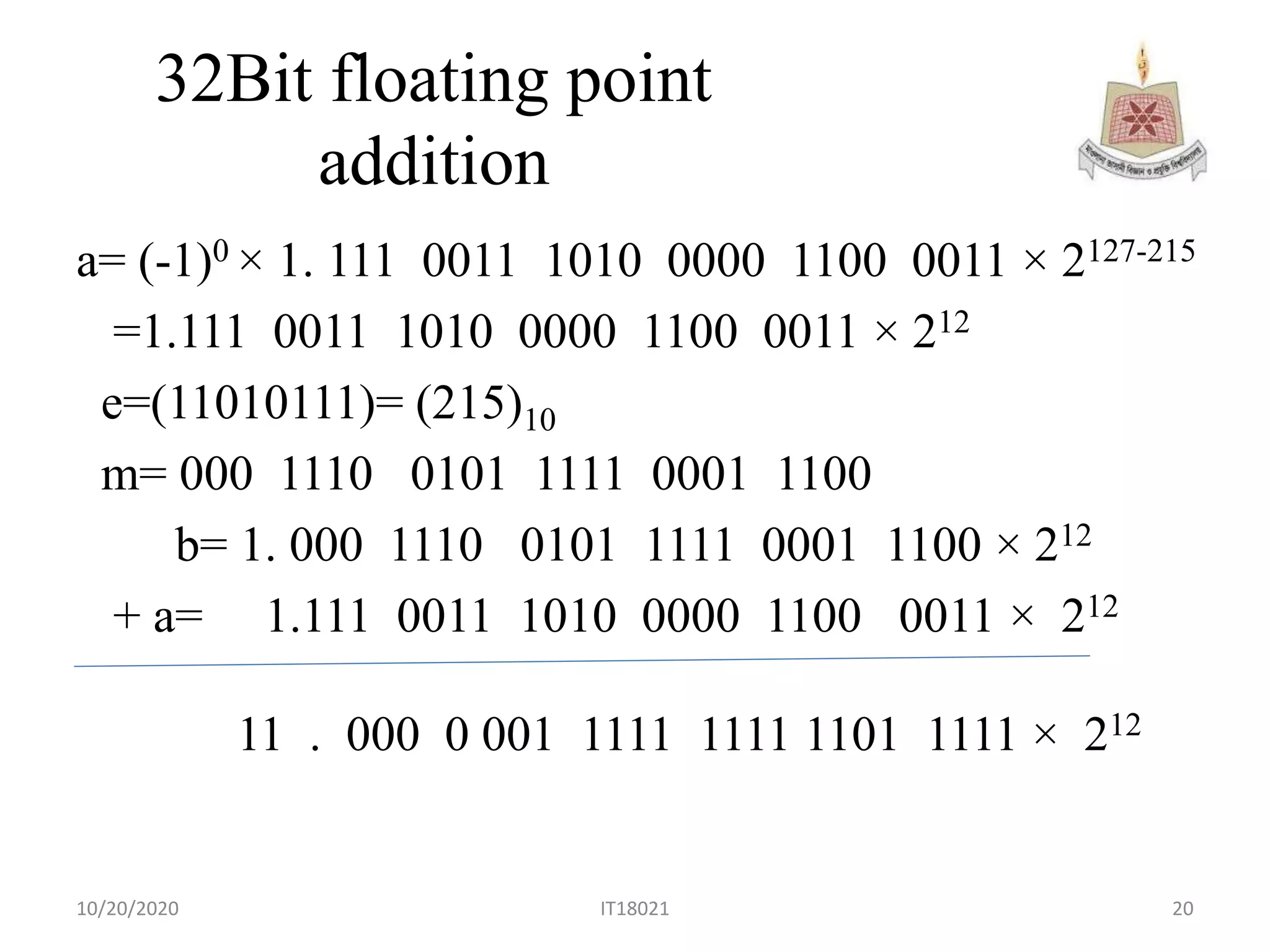
This presentation was made for student batch 2017-2018 of MBSTU. Here we will get
IEEE 32 bit floating representation .
IEEE 754 floating point representation
32 bit floating point Addition
Real numbers can be stored using floating point representation, which separates a real number into three parts: a sign bit, exponent, and mantissa. The exponent indicates the power of the base 10 that the mantissa is multiplied by. Common standards like IEEE 754 define single and double precision formats that allocate more bits for higher precision at the cost of range. Summarizing a floating point number involves determining the exponent by shifting the decimal, converting the number to a leading digit mantissa, and writing the sign, exponent, and mantissa based on the specified precision format.
In two's complement notation:
- The most significant bit represents the sign, with 0 indicating positive and 1 indicating negative.
- The remaining bits represent the magnitude, with the value determined by their place values.
- Negative numbers are calculated by taking the two's complement of the corresponding positive number.
- Two's complement notation allows for simple addition and subtraction operations on signed binary numbers.
Fixed-point and floating-point numbers can be represented in computers using binary numbers. Floating-point numbers represent numbers in scientific notation with a sign, mantissa, and exponent. In 8-bit floating point, numbers use 1 bit for sign, 3 bits for exponent, and 4 bits for mantissa, such as 0.001 x 21 = 2.25. Larger precision formats such as 32-bit and 64-bit floating point according to the IEEE standard use more bits for exponent and mantissa.
The document discusses binary arithmetic operations including addition, subtraction, multiplication, and division. It provides examples and step-by-step explanations of how to perform each operation in binary. For addition and subtraction, it explains the rules and concepts like carry bits and two's complement. For multiplication, it describes the shift-and-add method. And for division, it outlines the long division approach of shift-and-subtract in binary.
The document provides an overview of the Analog and Digital Electronics course taught at Matoshri College of Engineering & Research Centre. It includes information about the course's teaching scheme, examination scheme, objectives, and outcomes. The objectives are to design logical, sequential and combinational digital circuits using K-maps and to develop concepts related to operational amplifiers and rectifiers. The document also provides details of the topics to be covered in the first unit including Boolean algebra, K-maps, and the design of combinational circuits. It introduces concepts such as logic gates, number systems, and digital signals.
This presentation discusses different types of microoperations that can be performed on data stored in registers. It describes arithmetic microoperations like addition, subtraction, and increment/decrement. Logic microoperations perform bit-wise operations on registers like selective set, clear, complement, and masking. Shift microoperations serially transfer data in a register left or right through logical, circular, and arithmetic shifts. Arithmetic shifts preserve a number's sign during multiplication and division by 2 during left and right shifts.
Binary arithmetic is essential for digital computers and systems. It includes four rules for binary addition and subtraction. Binary addition examples show that adding two 1s results in a 1 in the next column with a carry of 1. Binary subtraction uses borrowing to subtract binary numbers, as shown through several examples.
Division algorithm involves dividing a dividend by a divisor to obtain a quotient and remainder. There are two types of division algorithms: restoring division and non-restoring division. Non-restoring division was demonstrated by dividing 8 by 3 in binary form using a divisor of 0011, a minuend of 1000, and a running difference stored in a accumulator to iteratively obtain the quotient 1000 and keep the division process non-negative.
This document discusses different types of codes used to encode information for transmission and storage. It begins by explaining that encoding is required to send information unambiguously over long distances and that decoding is needed to retrieve the original information. It then provides reasons for using coding, such as increasing transmission efficiency and enabling error correction. The document proceeds to describe binary coding and how increasing the number of bits allows more items to be uniquely represented. It also discusses properties of good codes like ease of use and error detection. Specific code types are then outlined, including binary coded decimal codes, unit distance codes, error detection codes, and alphanumeric codes. Gray code and excess-3 code are explained as examples.
Digital logic design deals with digital circuits and how to design digital hardware using logic gates. It involves working with binary and other number systems. Binary represents information using two states (0 and 1) which can be represented electrically using voltage levels. Converting between number systems like binary, decimal, and octal allows digital components to interface. Basic logic operations like addition, subtraction and multiplication can then be performed on binary numbers.
Digital Electronics- Number systems & codes VandanaPagar1
This document covers number systems including decimal, binary, hexadecimal and their representations. It discusses how to convert between different number bases including binary to decimal and hexadecimal to decimal. Binary operations like addition, subtraction and codes like binary coded decimal are explained. Non-weighted codes such as gray code are also introduced. Reference books on digital electronics and number systems are provided.
The document discusses different methods for representing integers and fractional numbers in binary, including sign and modulus representation, one's complement, two's complement, fixed point representation, and floating point representation. It provides examples and activities to help understand how to convert between decimal and binary representations using these methods.
This document discusses digital logic design and binary numbers. It covers topics such as digital vs analog signals, binary number systems, addition and subtraction in binary, and number base conversions between decimal, binary, octal, and hexadecimal. It also discusses complements, specifically 1's complement and radix complement. The purpose is to provide background information on fundamental concepts for digital logic design.
The document discusses different algorithms for multiplying binary numbers, including repeated addition, shifting registers, and the Booth algorithm. It provides examples of multiplying using these methods. The repeated addition method involves repeatedly adding the multiplicand. The shifting registers method uses separate registers for the multiplier, multiplicand, and product, and shifts and adds based on the multiplier bits. The Booth algorithm multiplies signed two's complement numbers by creating a table based on the multiplier and multiplicand, and performing additions or subtractions of the multiplicand while shifting based on the multiplier bits.
This document discusses various encoders and decoders used in digital circuits. It describes decimal to BCD encoders that convert decimal numbers to binary coded decimal. Priority encoders are discussed that compress multiple inputs into fewer outputs based on priority. Decoders discussed include BCD to decimal decoders that convert BCD to decimal numbers, and seven segment decoders that convert codes to activate the segments of seven segment displays. Applications of encoders and decoders include data communications, compression, security, and making data human readable.
This document provides information about different types of counters, including asynchronous counters, synchronous counters, MSI counters, and specific counter integrated circuits. It defines counters and describes their basic characteristics. It discusses asynchronous ripple counters and their timing. It provides examples of decade and binary counters. It describes synchronous counters and MSI counters like the 74LS163 4-bit synchronous counter. Finally, it provides truth tables, logic diagrams, and application information for common counter ICs like the 7490, 7492, 7493, and 74LS163.
This document provides information about a digital logic design course taught by Dr. Javaid Khurshid including the instructor and lab instructor contact details, lecture and lab schedule, grading policy, textbooks, and syllabus. The syllabus covers topics such as number systems, logic gates, Boolean algebra, combinational and sequential logic, memory, and microprocessors.
Booth's algorithm is a method for multiplying two signed or unsigned integers in binary representation more efficiently than straightforward algorithms. It uses fewer additions and subtractions by representing the multiplicand as 2's complement numbers. The algorithm loads the multiplicand and multiplier into registers, initializes a third register to 0, and performs bitwise shifts and arithmetic operations (addition/subtraction of the multiplicand) on the registers based on the values of bits from the multiplier. This process builds up the product one bit at a time in a third register.
This document provides information on circular linked lists including:
- Circular linked lists have the last element point to the first element, allowing traversal of the list to repeat indefinitely.
- Both singly and doubly linked lists can be made circular. Circular lists are useful for applications that require repeated traversal.
- Types of circular lists include singly circular (one link between nodes) and doubly circular (two links between nodes).
- Operations like insertion, deletion, and display can be performed on circular lists similarly to linear lists with some adjustments for the circular nature.
1) The document discusses parallel adders and subtractors for n-bit binary numbers. It specifically examines a 4-bit parallel adder that uses full adders connected in cascade, with the carry output of one full adder connected to the next's carry input.
2) A 4-bit parallel subtractor is also examined, which takes the 2's complement of the number to be subtracted and adds it to the other number using a 4-bit parallel adder.
3) Carry propagation time is discussed, which is the time it takes the carry to ripple through all the full adders in the parallel adder from the least to most significant bit.
Multiplexers and demultiplexers allow digital information from multiple sources to be routed through a single line. A multiplexer has multiple data inputs, select lines to choose an input, and a single output. A demultiplexer has a single input, select lines to choose an output, and multiple outputs. Bigger multiplexers and demultiplexers can be built by cascading smaller ones. Multiplexers can implement logic functions by using the select lines as variables and routing the input lines to the output.
This document discusses binary coded decimal (BCD). It defines BCD as a numerical code that assigns a 4-bit binary code to each decimal digit from 0 to 9. Numbers larger than 9 are expressed digit by digit in BCD. BCD is used because it is easy to encode/decode decimals and useful for digital systems that display decimal outputs. The document also describes how addition and subtraction are performed in BCD through binary addition rules and handling carries.
IEEE 754 Standards For Floating Point Representation.pdfkkumaraditya301
The document discusses floating point number representation according to the IEEE 754 standard. It describes:
- Single precision representation uses 32 bits with 1 sign bit, 8 exponent bits, and 23 mantissa bits.
- Double precision representation uses 64 bits with 1 sign bit, 11 exponent bits, and 52 mantissa bits.
- Floating point numbers are represented as (-1)S × 1.M × 2E, where S is the sign bit, M is the mantissa, and E is the exponent.
- Addition of floating point numbers involves normalizing the numbers to the same exponent before adding the mantissas.
1) Floating point numbers use a binary format defined by the IEEE 754 standard, which represents values as (-1)s × m × 2e, where s is the sign bit, m is the mantissa, and e is the exponent.
2) The mantissa is a fraction stored in bits with an implied leading 1, and the exponent is an offset from a bias of 127, allowing the representation of numbers between roughly 10-38 and 1038.
3) Converting values to their binary representation involves repeatedly multiplying/dividing the fractional part by 2 until the value is in the form 1.xxx × 2e, and the exponent tracks the number of times the decimal is shifted.
This document discusses number systems and Boolean algebra concepts relevant to switching theory and logic design. It covers topics like number systems, binary codes, Boolean algebra theorems and properties, switching functions, logic gate simplification, and multilevel logic implementations. Various number representations are examined, including binary, octal, hexadecimal, and binary coded decimal. Conversion between number bases is demonstrated. Boolean concepts like complements, addition, and subtraction using 1's and 2's complement are also summarized.
The document discusses digital and analog systems. It explains that digital systems represent information as discrete values using bits, whereas analog systems represent information as continuous values. It provides examples of digital and analog signals and discusses how a continuous analog signal can be converted to a discrete digital signal through sampling and quantization. It also covers binary, octal, and hexadecimal number systems and how to convert between them. Finally, it discusses binary addition and subtraction using complement representations.
The document discusses floating point numbers and the IEEE 754 standard. It describes how floating point numbers represent numbers with fractions using a sign bit, exponent field, and fraction field. The IEEE 754 standard uses a biased exponent representation for normalized floating point values, along with special values like infinity and NaN. It also details denormalized numbers, which allow gradual underflow to zero.
Bca 2nd sem-u-1.8 digital logic circuits, digital component floting and fixed...Rai University
Digital Logic Circuits, Digital Component and Data Representation discusses floating point numbers and the IEEE 754 standard. It describes how floating point numbers use a sign bit, exponent field, and fraction field to represent values too large or small for integers. The standard uses biased exponent representation and defines special values like infinity, zero, and NaN. Floating point numbers can be normalized, denormalized, or have special values and are ordered by magnitude.
International Journal of Engineering Research and DevelopmentIJERD Editor
Electrical, Electronics and Computer Engineering,
Information Engineering and Technology,
Mechanical, Industrial and Manufacturing Engineering,
Automation and Mechatronics Engineering,
Material and Chemical Engineering,
Civil and Architecture Engineering,
Biotechnology and Bio Engineering,
Environmental Engineering,
Petroleum and Mining Engineering,
Marine and Agriculture engineering,
Aerospace Engineering.
Digital and Logic Design Chapter 1 binary_systemsImran Waris
This document discusses binary number systems and digital computing. It covers binary numbers, number base conversions between decimal, binary, octal and hexadecimal. It also discusses binary coding techniques like binary-coded decimal, signed magnitude representation, one's complement and two's complement representations for negative numbers.
digital logic circuits, digital component floting and fixed pointRai University
This document provides an overview of floating point numbers and their representation. It discusses how floating point numbers are used to represent very large and small numbers with exponents. The IEEE 754 standard for floating point representation is described, including the use of sign-magnitude, biased exponents, normalization, denormalization and special values like infinity and NaN. Single and double precision floating point number formats are defined according to IEEE 754. Methods for converting between decimal and binary floating point values are demonstrated through examples.
B.sc cs-ii-u-1.8 digital logic circuits, digital component floting and fixed ...Rai University
Digital Logic Circuits, Digital Component and Data Representation discusses floating point numbers and the IEEE 754 standard. It describes how floating point numbers use a sign bit, exponent field, and fraction field to represent values in scientific notation. It also summarizes the IEEE 754 standard for single and double precision floating point numbers, including how special values like infinity and NaN are represented.
The document provides information about digital electronics and digital systems. It introduces digital logic and how digital systems represent information using discrete binary values of 0 and 1. Digital computers are able to manipulate this discrete digital data through programs. Common number systems like binary, octal, hexadecimal and their conversions to decimal are explained. Signed and unsigned binary numbers are also discussed.
This document contains slides for a lecture on digital logic design. It introduces the topic and provides an outline of contents to be covered, including number systems, function minimization methods, combinational and sequential systems, and hardware design languages. It also lists the speaker's contact details and information about textbook references, grading policies, and acknowledgments. The first chapter focuses on number systems, covering binary, decimal, octal, and hexadecimal representation, addition, subtraction, signed numbers, binary-coded decimal, and other coding systems. Examples of converting between different bases are provided.
This document provides lecture notes on digital system design. It covers topics like logic simplification, combinational logic design, understanding binary and other number systems, binary operations, and Boolean algebra. The first section discusses decimal, binary, octal and hexadecimal number systems. Later sections explain binary addition, subtraction, multiplication and conversions between number bases. Signed number representations like 1's complement and 2's complement are also introduced. Finally, the document discusses Boolean algebra, logic functions, truth tables, and basic logic gates like AND and INVERTER.
Introduction to Information Technology Lecture 2MikeCrea
Number Systems
Types of number systems
Number bases
Range of possible numbers
Conversion between number bases
Common powers
Arithmetic in different number bases
Shifting a number
The document discusses floating point arithmetic and assembly language basics. It provides details about an upcoming exam, Project #6 which involves using C to write a library module and driver module. It also reviews the system bus model and describes the main components of an ARM microprocessor including the RAM, control unit, integer unit, floating point unit, and optional coprocessor.
The document introduces computer architecture and system software. It discusses the differences between computer organization and computer architecture. It describes the basic components of a computer based on the Von Neumann architecture, which consists of four main sub-systems: memory, ALU, control unit, and I/O. The document also discusses bottlenecks of the Von Neumann architecture and differences between microprocessors and microcontrollers. It covers computer arithmetic concepts like integer representation, floating point representation using IEEE 754 standard, and number bases conversion. Additional topics include binary operations like addition, subtraction using complements, and multiplication algorithms like Booth's multiplication.
The document discusses digital systems and binary numbers. It defines digital systems as systems that manipulate discrete elements of information, such as binary digits represented by the values 0 and 1. It explains how binary numbers are represented and arithmetic operations like addition, subtraction, multiplication and division are performed on binary numbers. It also discusses number base conversions between decimal, binary, octal and hexadecimal numbering systems. Finally, it covers binary complements including 1's complement, 2's complement and subtraction using complements.
This document provides an introduction to a digital design course. It discusses the recommended textbook, course description, grading breakdown, and course outline. The course focuses on fundamental digital concepts like number systems, Boolean algebra, logic gates, combinational and sequential logic. It will cover topics such as binary numbers, Boolean functions, logic gate minimization, adders/subtractors, multiplexers, flip-flops, and finite state machines. Students are expected to attend every lecture and participate in classroom discussions. Grades will be based on projects, midterm exams, and quizzes/assignments.
This document provides an overview of digital systems and binary numbers. It discusses topics such as analog vs digital signals, different number systems including binary, octal, decimal and hexadecimal, binary operations like addition and multiplication, and number base conversions. It also covers binary complements including 1's complement and 2's complement, which are important for signed binary numbers and binary subtraction.
Exponential notation can be used to represent very large and very small numbers in a normalized form. A floating point number uses a sign, exponent, and mantissa to represent values in a fixed number of bits. Common standards like IEEE 754 specify single and double precision formats that use 1 sign bit, 8 or 11 exponent bits, and 23 or 52 mantissa bits respectively. Calculations with floating point numbers require aligning the exponents before adding or multiplying the mantissas and adjusting the result exponent.
Similar to IEEE floating point representation (20)
We have compiled the most important slides from each speaker's presentation. This year’s compilation, available for free, captures the key insights and contributions shared during the DfMAy 2024 conference.
ACEP Magazine edition 4th launched on 05.06.2024Rahul
This document provides information about the third edition of the magazine "Sthapatya" published by the Association of Civil Engineers (Practicing) Aurangabad. It includes messages from current and past presidents of ACEP, memories and photos from past ACEP events, information on life time achievement awards given by ACEP, and a technical article on concrete maintenance, repairs and strengthening. The document highlights activities of ACEP and provides a technical educational article for members.
Understanding Inductive Bias in Machine LearningSUTEJAS
This presentation explores the concept of inductive bias in machine learning. It explains how algorithms come with built-in assumptions and preferences that guide the learning process. You'll learn about the different types of inductive bias and how they can impact the performance and generalizability of machine learning models.
The presentation also covers the positive and negative aspects of inductive bias, along with strategies for mitigating potential drawbacks. We'll explore examples of how bias manifests in algorithms like neural networks and decision trees.
By understanding inductive bias, you can gain valuable insights into how machine learning models work and make informed decisions when building and deploying them.
A SYSTEMATIC RISK ASSESSMENT APPROACH FOR SECURING THE SMART IRRIGATION SYSTEMSIJNSA Journal
The smart irrigation system represents an innovative approach to optimize water usage in agricultural and landscaping practices. The integration of cutting-edge technologies, including sensors, actuators, and data analysis, empowers this system to provide accurate monitoring and control of irrigation processes by leveraging real-time environmental conditions. The main objective of a smart irrigation system is to optimize water efficiency, minimize expenses, and foster the adoption of sustainable water management methods. This paper conducts a systematic risk assessment by exploring the key components/assets and their functionalities in the smart irrigation system. The crucial role of sensors in gathering data on soil moisture, weather patterns, and plant well-being is emphasized in this system. These sensors enable intelligent decision-making in irrigation scheduling and water distribution, leading to enhanced water efficiency and sustainable water management practices. Actuators enable automated control of irrigation devices, ensuring precise and targeted water delivery to plants. Additionally, the paper addresses the potential threat and vulnerabilities associated with smart irrigation systems. It discusses limitations of the system, such as power constraints and computational capabilities, and calculates the potential security risks. The paper suggests possible risk treatment methods for effective secure system operation. In conclusion, the paper emphasizes the significant benefits of implementing smart irrigation systems, including improved water conservation, increased crop yield, and reduced environmental impact. Additionally, based on the security analysis conducted, the paper recommends the implementation of countermeasures and security approaches to address vulnerabilities and ensure the integrity and reliability of the system. By incorporating these measures, smart irrigation technology can revolutionize water management practices in agriculture, promoting sustainability, resource efficiency, and safeguarding against potential security threats.
Low power architecture of logic gates using adiabatic techniquesnooriasukmaningtyas
The growing significance of portable systems to limit power consumption in ultra-large-scale-integration chips of very high density, has recently led to rapid and inventive progresses in low-power design. The most effective technique is adiabatic logic circuit design in energy-efficient hardware. This paper presents two adiabatic approaches for the design of low power circuits, modified positive feedback adiabatic logic (modified PFAL) and the other is direct current diode based positive feedback adiabatic logic (DC-DB PFAL). Logic gates are the preliminary components in any digital circuit design. By improving the performance of basic gates, one can improvise the whole system performance. In this paper proposed circuit design of the low power architecture of OR/NOR, AND/NAND, and XOR/XNOR gates are presented using the said approaches and their results are analyzed for powerdissipation, delay, power-delay-product and rise time and compared with the other adiabatic techniques along with the conventional complementary metal oxide semiconductor (CMOS) designs reported in the literature. It has been found that the designs with DC-DB PFAL technique outperform with the percentage improvement of 65% for NOR gate and 7% for NAND gate and 34% for XNOR gate over the modified PFAL techniques at 10 MHz respectively.
Literature Review Basics and Understanding Reference Management.pptxDr Ramhari Poudyal
Three-day training on academic research focuses on analytical tools at United Technical College, supported by the University Grant Commission, Nepal. 24-26 May 2024
International Conference on NLP, Artificial Intelligence, Machine Learning an...gerogepatton
International Conference on NLP, Artificial Intelligence, Machine Learning and Applications (NLAIM 2024) offers a premier global platform for exchanging insights and findings in the theory, methodology, and applications of NLP, Artificial Intelligence, Machine Learning, and their applications. The conference seeks substantial contributions across all key domains of NLP, Artificial Intelligence, Machine Learning, and their practical applications, aiming to foster both theoretical advancements and real-world implementations. With a focus on facilitating collaboration between researchers and practitioners from academia and industry, the conference serves as a nexus for sharing the latest developments in the field.
International Conference on NLP, Artificial Intelligence, Machine Learning an...
IEEE floating point representation
1. Computer Organization And
Architecture
Presented by :Maskur Al Shal Sabil
ID: IT18021
Dept : Information & Communication Technology
Mawlana Bhashani Science & Technology University
10/20/2020 1IT18021
2. Learning Outcome
• Floating Point Representation
• IEEE 754 Standards For Floating Point
Representation
• Single Precision
• Double Precision
• Single Precision Addition
10/20/2020 IT18021 2
3. Floating Point
Representation
The floating point representation does not reserve any
specific number of bits for the integer part or the
fractional part. Instead it reserve a certain point for
the number and a certain number of bit where within
that number the decimal place sits called the
exponent.
10/20/2020 IT18021 3
4. IEEE 754 Floating point
representation
According to IEEE754 standard, the floating point
number is represented in following ways:
• Half Precision(16bit):1 sign bit,5 bit exponent & 10
bit mantissa
• Single Precision(32bit):1 sign bit,8 bit exponent &
23 bit mantissa
• Double Precision(64bit):1 sign bit,11 bit exponent &
52bit mantissa
• Extend precision(128bit):1 sign bit,15bit exponent &
112 bit mantissa
10/20/2020 IT18021 4
5. Floating Point
Representation
10/20/2020 IT18021 5
The floating point representation has two part : the one
signed part called the mantissa and other called the
exponent.
(sign) × mantissa × 2exponent
Sign Bit Exponent Mantissa
8. IEEE 32-bit floating
point representation
10/20/2020 IT18021 8
1-bit 8 -bit 23- bit
Number representation: (-1)S × 1.M× 2E-127
Sign Bit Biased Exponent Trailing Significand bit or
Mantissa
9. IEEE 32-bit floating point
representation
(45.45)10=(101101.011100)2
Step -1: Normalize the number
Step-2: Take the exponent and mantissa.
Step-3:Find. the bias exponent by adding 127
Step-3:Normalize the mantissa by adding 1.
Step -4:Set the sign bit 0 if positive otherwise 1 .
For n bit exponent bias is 2n-1-1
10/20/2020 IT18021 9
13. IEEE 64-bit floating point
representation
1bit 11bits 52bits
Here we use 211-1 – 1 = 1023 as bias value.
10/20/2020 IT18021 13
Sign Bit Biased Exponent Trailling Significand bit or
Mantissa
16. Addition of floating point
First consider addition in base 10 if exponent is the
same the just add the significand
5.0E+2
+7.0E+2
12.0E+2=1.2E+3
10/20/2020 IT18021 16
17. Addition of floating point
1.2232E+3 + 4.211E+5
First Normalize to higher exponent
a. Find the difference between exponents
b. Shift smaller number right by that amount
1.2232E+3=.012232E+5
10/20/2020 IT18021 17
18. Addition of floating point
4.211 E+5
+ 0.012232 E+5
4.223232 E+5
10/20/2020 IT18021 18
19. 32Bit floating point addition
a 0 1101 0111 111 0011 1010 0000 1100 0011
b 0 1101 0111 000 1110 0101 1111 0001 1100
Find the 32 bit floating point number representation of
a+b .
Here,
e=(11010111)= (215)10
m= (111 0011 1010 0000 1100 0011)
10/20/2020 IT18021 19