Downloaded 146 times


![• Example:
Consider a multirate signal processing problem:
i. State with the aid of block diagrams the process
of changing sampling rate by a non-integer factor.
ii.Develop an expression for the output y[n] and
g[n] as a function of input x[n] for the multirate
structure of fig .
20krishnanaik.ece@gmail.com](https://image.slidesharecdn.com/digitalsignalprocessorpart4-170910152949/85/Digital-signal-processor-part4-20-320.jpg)


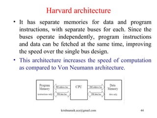


This document discusses digital signal processing and multirate digital signal processing. It covers topics like sampling rate conversion using interpolation and decimation filters, polyphase filters, and applications of multirate DSP systems. It also describes digital signal processors, focusing on architectures like Von Neumann, Harvard, and SHARC that are optimized for digital signal processing tasks through features like separate data/program memories, pipelining, and multiplier-accumulator units.