Chapter 1: DigitalSystems and Binary Numbers
1.1 Digital Systems
1.2 Binary Numbers
1.3 NumberBase Conversions
1.4 Octal and Hexadecimal Numbers
1.5 Complements of Numbers
1.6 Signed Binary Numbers
1.6 Signed Binary Numbers
1.7 Binary Codes
1 8 Binary Storage and Registers
1.8 Binary Storage and Registers
1.9 Binary Logic
NCNU_2013_DD_1_1
2.
Digital Systems
• Digitalage:
– digital systems play a prominent role in everyday life; used in communication, business
transactions traffic control spacecraft guidance medical treatment weather monitoring the
transactions, traffic control, spacecraft guidance, medical treatment, weather monitoring, the
Internet, and many other commercial, industrial, and scientific enterprises
• Digital system examples:
– mobile phone
– digital camera
digital versatile disc (DVD) personal digital assistance (PDA) MP3
– digital versatile disc (DVD), personal digital assistance (PDA), MP3, …
– digital TV
– most, if not all, of these devices have an embedded specialpurpose digital computer
• Digital computers:
– generality or flexibility
if d h h f i i h d di
What you will learn in the micro-processor course.
– users can specify and change the program, a sequence of instructions, or the data according to
the specific need
– generalpurpose digital computers can perform a variety of informationprocessing tasks that
NCNU_2013_DD_1_2
range over a wide spectrum of applications
3.
Signal
• Digital systemsmanipulate discrete elements of information represented in a digital
system by physical quantities called signals.
V lt d t th t l t i l i l
• Voltages and currents are the most common electrical signals.
• The signals in most presentday electronic digital systems use just two discrete values or
binary values
y
• Binary values are represented abstractly by:
- digit: 0 and 1 A binary digit is called a bit.
- logic: False (F) and True (T)
- level: Low (L) and High (H)
- word: Yes and No
word: Yes and No
- state: On and Off.
• Discrete elements of information are represented with groups of bits called binary codes.
For example: 01112 = 710
• Analogtodigital converters perform quantization process on analog (continuous)
signals to form a digital (discrete) signals
NCNU_2013_DD_1_3
signals to form a digital (discrete) signals.
4.
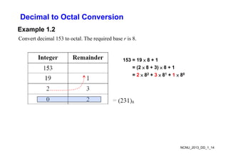
General-purpose Digital Computer
•The major parts of a computer are a memory unit, a central processing unit (CPU), and
input–output units (I/O). [check these in your Computer course]
M it t ll i t t t d i t di t d t
• Memory unit stores programs as well as input, output, and intermediate data.
• CPU performs arithmetic and dataprocessing operations as specified by the program.
• The program and data prepared by a user are transferred into memory by means of an
The program and data prepared by a user are transferred into memory by means of an
input device such as a keyboard.
• An output device, such as a printer, receives the results of the computations, and the
i d l d h
printed results are presented to the user.
• Voice, image, finger touch, gesture, brain wave, …, also can be used as input or output.
• Communication unit provides interaction with other users through the Internet
• Communication unit provides interaction with other users through the Internet.
• A digital computer can perform not only arithmetic computations and logical operations
but also can make decisions based on internal and external conditions.
NCNU_2013_DD_1_4
5.
Hardware Description Language(HDL)
• A digital system is an interconnection of digital modules.
• To understand the operation of each digital module, it is necessary to have a basic
k l d f di it l i it d th i l i l f ti
knowledge of digital circuits and their logical function.
• A major trend in digital design methodology is the use of a hardware description
language (HDL) to describe and simulate the functionality of a digital circuit.
g g ( ) y g
• An HDL resembles a programming language and is suitable for describing digital
circuits in textual form, simulating a digital system to verify its operation before
hardware is built and automating the design process in conjunction with logic synthesis
hardware is built, and automating the design process in conjunction with logic synthesis
tools.
• Ignorance of industry’s practices on HDL modeling will lead to cute, but worthless,
HDL models that may simulate a phenomenon, but that cannot be synthesized by design
tools, or to models that waste silicon area or synthesize to hardware that cannot operate
correctly. [take the Digital System Design course for more learning on HDL]
y [ g y g g ]
NCNU_2013_DD_1_5
6.
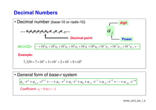
Decimal Numbers
• Decimalnumber (base-10 or radix-10)
a
digit
… a5a4a3a2a1a0.a1a2a3…
Decimal point
j
a
Power
5 4 3 2 1 0 1 2 3
5 4 3 2 1 0 1 2 3
10 10 10 10 10 10 10 10 10
a a a a a a a a a
Example:
3 2 1 0
7,329 7 10 3 10 2 10 9 10
Example:
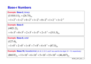
• General form of base-r system
1 2 1 1 2
1 2 1 1 2
1 2 1 0 1 2
n n m
n n m
a r a r a r a r a a r a r a r
Coefficient: aj = 0 to r 1
NCNU_2013_DD_1_6
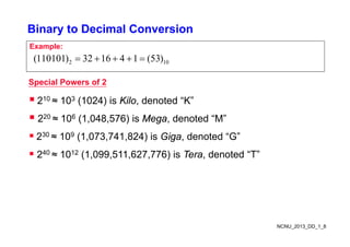
Binary to DecimalConversion
Example:
2 10
(110101) 32 16 4 1 (53)
Special Powers of 2
210 ≈ 103 (1024) is Kilo, denoted “K”
220 ≈ 106 (1,048,576) is Mega, denoted “M”
( ) g
230 ≈ 109 (1,073,741,824) is Giga, denoted “G”
240 1012 (1 099 511 627 776) i T d t d “T”
240 ≈ 1012 (1,099,511,627,776) is Tera, denoted “T”
NCNU_2013_DD_1_8
9.
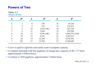
Powers of Two
•A byte is equal to eight bits and usually used in computer capacity.
• A computer hard disk with four gigabytes of storage has a capacity of 4G = 232 bytes
(approximately 4 billion bytes).
A b i 1024 i b i l 1 illi b
NCNU_2013_DD_1_9
• A terabyte is 1024 gigabytes, approximately 1 trillion bytes.
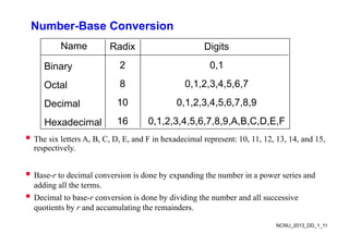
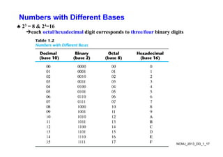
Number-Base Conversion
Name RadixDigits
Binary 2 0 1
Binary 2 0,1
Octal 8 0,1,2,3,4,5,6,7
Decimal 10 0,1,2,3,4,5,6,7,8,9
Hexadecimal 16 0 1 2 3 4 5 6 7 8 9 A B C D E F
Hexadecimal 16 0,1,2,3,4,5,6,7,8,9,A,B,C,D,E,F
The six letters A, B, C, D, E, and F in hexadecimal represent: 10, 11, 12, 13, 14, and 15,
respectively.
p y
Base-r to decimal conversion is done by expanding the number in a power series and
y p g p
adding all the terms.
Decimal to base-r conversion is done by dividing the number and all successive
quotients by r and accumulating the remainders
NCNU_2013_DD_1_11
quotients by r and accumulating the remainders.
12.
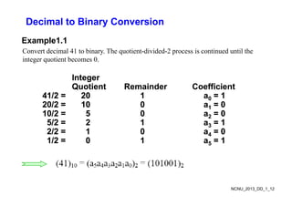
Decimal to BinaryConversion
Example1.1
Convert decimal 41 to binary. The quotient-divided-2 process is continued until the
integer quotient becomes 0.
Integer
Integer
Integer
Integer
Quotient
Quotient Remainder
Remainder Coefficient
Coefficient
41/2 =
41/2 = 20
20 1
1 a
a0
0 =
= 1
1
20/2 =
20/2 = 10
10 0
0 a
a =
= 0
0
20/2 =
20/2 = 10
10 0
0 a
a1
1 =
= 0
0
10/2 =
10/2 = 5
5 0
0 a
a2
2 =
= 0
0
5/2 =
5/2 = 2
2 1
1 a
a3
3 =
= 1
1
3
3
2/2 =
2/2 = 1
1 0
0 a
a4
4 =
= 0
0
1/2 =
1/2 = 0
0 1
1 a
a5
5 =
= 1
1
NCNU_2013_DD_1_12
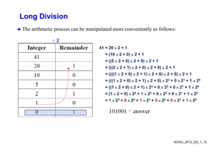
Decimal to OctalConversion
Example 1.2
Convert decimal 153 to octal. The required base r is 8.
153 = 19 × 8 + 1
= (2 × 8 + 3) × 8 + 1
= 2 × 82 + 3 × 81 + 1 × 80
NCNU_2013_DD_1_14
15.
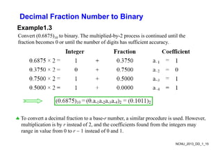
Decimal Fraction Numberto Binary
Example1.3
Convert (0.6875)10 to binary. The multiplied-by-2 process is continued until the
fraction becomes 0 or until the number of digits has sufficient accuracy
fraction becomes 0 or until the number of digits has sufficient accuracy.
To convert a decimal fraction to a base-r number, a similar procedure is used. However,
multiplication is by r instead of 2, and the coefficients found from the integers may
range in value from 0 to r 1 instead of 0 and 1
NCNU_2013_DD_1_15
range in value from 0 to r 1 instead of 0 and 1.
16.
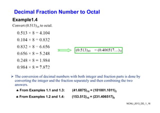
Decimal Fraction Numberto Octal
E l 1 4
Example1.4
Convert (0.513)10 to octal.
The conversion of decimal numbers with both integer and fraction parts is done by
converting the integer and the fraction separately and then combining the two
From Examples 1.1 and 1.3: (41.6875)10 = (101001.1011)2
g g p y g
answers.
NCNU_2013_DD_1_16
From Examples 1.2 and 1.4: (153.513)10 = (231.406517)8
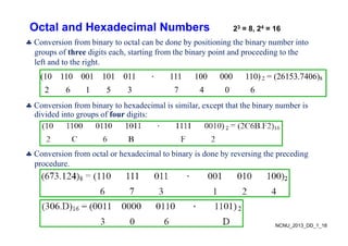
Octal and HexadecimalNumbers
i f bi l b d b i i i h bi b i
23 = 8, 24 = 16
Conversion from binary to octal can be done by positioning the binary number into
groups of three digits each, starting from the binary point and proceeding to the
left and to the right.
(10 110 001 101 011 . 111 100 000 110) 2 = (26153.7406)8
2 6 1 5 3 7 4 0 6
Conversion from binary to hexadecimal is similar, except that the binary number is
divided into groups of four digits:
C i f l h d i l bi i d b i h di
Conversion from octal or hexadecimal to binary is done by reversing the preceding
procedure.
NCNU_2013_DD_1_18
19.
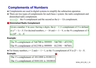
Complements of Numbers
C l t d i di it l t t i lif th bt ti ti
Complements are used in digital systems to simplify the subtraction operation
There are two types of complements for each base-r system: the radix complement and
diminished radix complement.
h l d h d h ( ) l
the r's complement and the second as the (r 1)'s complement.
■ Diminished Radix Complement
Example:
For binary numbers, r = 2 and r – 1 = 1, so the 1's complement of N is (2n 1) – N.
Example:
NCNU_2013_DD_1_19
20.
Complements of Numbers
■Radix Complement
The r's complement of an n-digit number N in base r is defined as rn – N for N ≠ 0
and as 0 for N = 0 Comparing with the (r 1) 's complement we note that the r's
and as 0 for N 0. Comparing with the (r 1) s complement, we note that the r s
complement is obtained by adding 1 to the (r 1) 's complement, since rn – N =
[(rn 1) – N] + 1.
Example: Base-10
The 10's complement of 012398 is 987602
Th 10' l t f 246700 i 753300
The 10's complement of 246700 is 753300
Example: Base-2
The 2's complement of 1101100 is 0010100
The 2's complement of 0110111 is 1001001
NCNU_2013_DD_1_20
21.
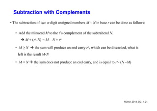
Subtraction with Complements
•The subtraction of two n-digit unsigned numbers M – N in base r can be done as follows:
• Add the minuend M to the r’s complement of the subtrahend N.
M + (rn-N) = M – N + rn
• M ≥ N the sum will produce an end carry rn, which can be discarded, what is
left is the result M-N
e t s t e esu t N
• M < N the sum does not produce an end carry, and is equal to rn- (N –M)
NCNU_2013_DD_1_21
22.
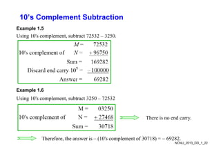
10’s Complement Subtraction
Example1.5
Using 10's complement, subtract 72532 – 3250.
Example 1.6
Using 10's complement, subtract 3250 – 72532
There is no end carry.
NCNU_2013_DD_1_22
Therefore, the answer is – (10's complement of 30718) = 69282.
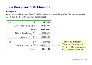
23.
2’s Complement Subtraction
Example1.7
Given the two binary numbers X = 1010100 and Y = 1000011, perform the subtraction (a)
X – Y and (b) Y X by using 2's complement.
( ) y g p
There is no end carry.
Therefore, the answer is
Y – X = (2's complement
Y X (2 s complement
of 1101111) = 0010001.
NCNU_2013_DD_1_23
24.
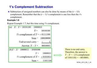
1’s Complement Subtraction
Sb i f i d b l b d b f h ( 1)'
Subtraction of unsigned numbers can also be done by means of the (r 1)'s
complement. Remember that the (r 1) 's complement is one less then the r's
complement.
Example 1.8
Repeat Example 1.7, but this time using 1's complement.
There is no end carry
There is no end carry,
Therefore, the answer is
Y – X = (1's complement
f 1101110) 0010001
NCNU_2013_DD_1_24
of 1101110) = 0010001.
25.
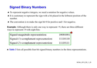
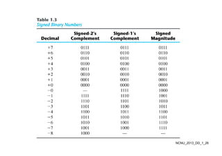
Signed Binary Numbers
To represent negative integers, we need a notation for negative values.
It is customary to represent the sign with a bit placed in the leftmost position of the
number
number.
The convention is to make the sign bit 0 for positive and 1 for negative.
E l Al h h h i l 9 h h diff
Example: Although there is only one way to represent +9, there are three different
ways to represent -9 with eight bits:
Table 3 lists all possible four bit signed binary numbers in the three representations
Table 3 lists all possible four-bit signed binary numbers in the three representations.
NCNU_2013_DD_1_25
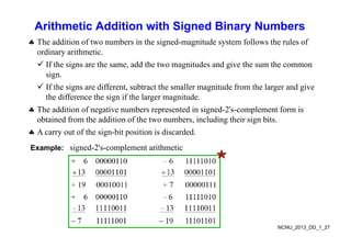
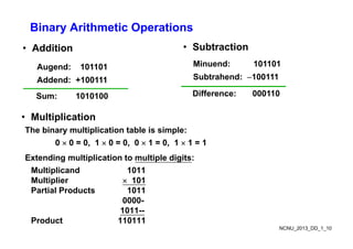
Arithmetic Addition withSigned Binary Numbers
Th ddi i f b i h i d i d f ll h l f
The addition of two numbers in the signed-magnitude system follows the rules of
ordinary arithmetic.
If the signs are the same, add the two magnitudes and give the sum the common
g , g g
sign.
If the signs are different, subtract the smaller magnitude from the larger and give
th diff th i if th l it d
the difference the sign if the larger magnitude.
The addition of negative numbers represented in signed-2's-complement form is
obtained from the addition of the two numbers, including their sign bits.
g g
A carry out of the sign-bit position is discarded.
Example: signed-2's-complement arithmetic
NCNU_2013_DD_1_27
28.
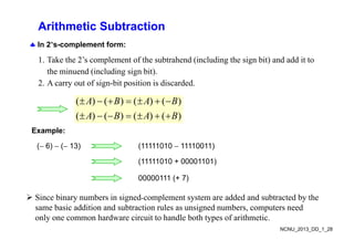
Arithmetic Subtraction
In2’s-complement form:
1. Take the 2’s complement of the subtrahend (including the sign bit) and add it to
the minuend (including sign bit).
2. A carry out of sign-bit position is discarded.
( ) ( ) ( ) ( )
( ) ( ) ( ) ( )
A B A B
A B A B
Example:
( 6) ( 13) (11111010 11110011)
(11111010 + 00001101)
00000111 (+ 7)
( )
Since binary numbers in signedcomplement system are added and subtracted by the
same basic addition and subtraction rules as unsigned numbers, computers need
NCNU_2013_DD_1_28
same basic addition and subtraction rules as unsigned numbers, computers need
only one common hardware circuit to handle both types of arithmetic.
29.
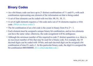
Binary Codes
• Annbit binary code can have up to 2n distinct combinations of 1’s and 0’s, with each
combination representing one element of the information set that is being coded.
A t f f l t b d d ith t bit 00 01 10 11
• A set of four elements can be coded with two bits: 00, 01, 10, 11.
• A set of eight elements requires a 3bit code and a set of 16 elements requires a 4bit
code. (What are these codes?)
( )
• The bit combination of an nbit code is the count in binary from 0 to 2n - 1.
• Each element must be assigned a unique binary bit combination, and no two elements
h h l h i h d i ill b bi
can have the same value; otherwise, the code assignment will be ambiguous.
• Although the minimum number of bits required to code 2n distinct quantities is n, there is
no maximum number of bits that may be used for a binary code. For example, the 10
no maximum number of bits that may be used for a binary code. For example, the 10
decimal digits can be coded with 10 bits, and each decimal digit can be assigned a bit
combination of nine 0’s and a 1. In this particular binary code, the digit 6 is assigned the
bit combination 0001000000 (It is called one-hot code )
bit combination 0001000000. (It is called one-hot code.)
NCNU_2013_DD_1_29
30.
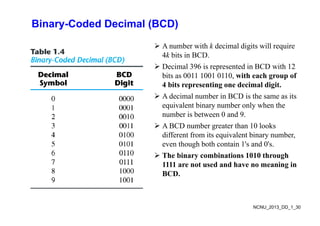
Binary-Coded Decimal (BCD)
A number with k decimal digits will require
4k bits in BCD.
Decimal 396 is represented in BCD with 12
bits as 0011 1001 0110, with each group of
4 bits representing one decimal digit.
p g g
A decimal number in BCD is the same as its
equivalent binary number only when the
b i b t 0 d 9
number is between 0 and 9.
A BCD number greater than 10 looks
different from its equivalent binary number,
q y ,
even though both contain 1's and 0's.
The binary combinations 1010 through
1111 are not used and have no meaning in
1111 are not used and have no meaning in
BCD.
NCNU_2013_DD_1_30
31.
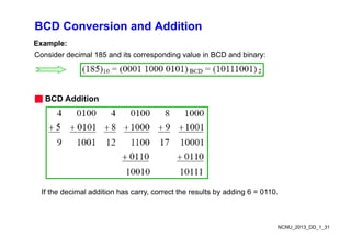
BCD Conversion andAddition
Example:
Consider decimal 185 and its corresponding value in BCD and binary:
■ BCD Additi
■ BCD Addition
If the decimal addition has carry, correct the results by adding 6 = 0110.
NCNU_2013_DD_1_31
32.
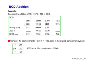
BCD Addition
Example:
Consider theaddition of 184 + 576 = 760 in BCD:
■ Consider the addition (+375) + (-240) = +135, done in the signedcomplement system:
9760 is the 10’s complement of 0240.
NCNU_2013_DD_1_32
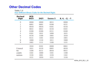
Gray Code
Gd h l bit i th d
Gray code changes only one bit in the code
group going from one number to the next.
For example, going from 7 to 8, the Gray code
p , g g , y
changes from 0100 to 1100. Only the first bit
changes, from 0 to 1; the other three bits remain
the same
the same.
If binary numbers are used, a change, for
example, from 0111 to 1000 may produce an
i di b 1001 if h
intermediate erroneous number 1001 if the
value of the rightmost bit takes longer to change
than do the values of the other three bits.
NCNU_2013_DD_1_34
35.
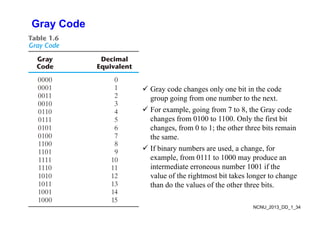
Gray Code (Continued)
•Does this special Gray code property have any value?
• Example: Optical Shaft Encoder
111 000 100 000
B 0
110 001
B 1
B 2
101 001
010
G 0
G 1
G 2
111
010
011
100
101
G 0
111
011
010
110
011
100
(a) Binary Code for Positions 0 through 7
010
110
(b) Gray Code for Positions 0 through 7
NCNU_2013_DD_1_35
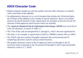
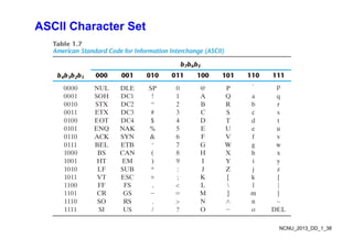
ASCII Character Code
•Digital computers handle not only the numbers, but also other characters or symbols,
such as the letters of the alphabet.
A l h i h t t i t f l t th t i l d th 10 d i l di it
• An alphanumeric character set is a set of elements that includes the 10 decimal digits,
the 26 letters of the alphabet, and a number of special characters. Such a set contains
between 36 and 64 elements if only capital letters are included, or between 64 and 128
elements if both uppercase and lowercase letters are included.
• The American Standard Code for Information Interchange (ASCII) uses seven bits to
code 128 characters, as shown in Table 1.7 .
code 128 characters, as shown in Table 1.7 .
• The 7 bits of the code are designated by b1 through b7, with b7 the most significant bit.
• The letter A, for example, is represented in ASCII as 1000001 (column 100, row 0001).
• The ASCII code also contains 94 graphic characters that can be printed and 34
nonprinting characters used for various control functions.
Th hi h t i t f th 26 l tt (A th h Z) th 26
• The graphic characters consist of the 26 uppercase letters (A through Z), the 26
lowercase letters (a through z), the 10 numerals (0 through 9), and 32 special printable
characters, such as %, *, and $.
NCNU_2013_DD_1_37
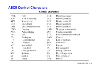
UNICODE
• UNICODE extendsASCII to 65,536 universal characters codes
For encoding characters in world languages
– For encoding characters in world languages
– Available in many modern applications
– 2 byte (16-bit) code words
2 byte (16 bit) code words
– See Reading Supplement – Unicode on the Companion Website
http://www.prenhall.com/mano
NCNU_2013_DD_1_40
41.
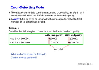
Error-Detecting Code
Todetect errors in data communication and processing, an eighth bit is
sometimes added to the ASCII character to indicate its parity.
A parity bit is an extra bit included with a message to make the total
A parity bit is an extra bit included with a message to make the total
number of 1's either even or odd.
Example:
Consider the following two characters and their even and odd parity:
parity bit
What kind of errors can be detected?
Can the error be corrected?
NCNU_2013_DD_1_41
42.
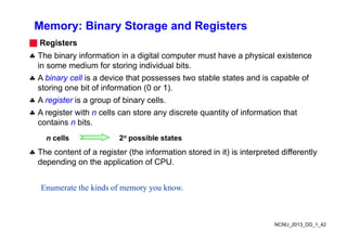
Memory: Binary Storageand Registers
■ Registers
The binary information in a digital computer must have a physical existence
in some medium for storing individual bits
in some medium for storing individual bits.
A binary cell is a device that possesses two stable states and is capable of
storing one bit of information (0 or 1).
A register is a group of binary cells.
A register with n cells can store any discrete quantity of information that
contains n bits
contains n bits.
Th t t f i t (th i f ti t d i it) i i t t d diff tl
n cells 2n possible states
The content of a register (the information stored in it) is interpreted differently
depending on the application of CPU.
Enumerate the kinds of memory you know.
NCNU_2013_DD_1_42
43.
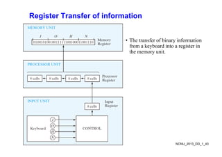
Register Transfer ofinformation
• The transfer of binary information
y
from a keyboard into a register in
the memory unit.
NCNU_2013_DD_1_43
44.
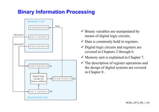
Binary Information Processing
Bi i bl i l t d b
Binary variables are manipulated by
means of digital logic circuits.
Data is commonly hold in registers.
y g
Digital logic circuits and registers are
covered in Chapters 2 through 6.
i i l i d i h
Memory unit is explained in Chapter 7.
The description of register operations and
the design of digital systems are covered
the design of digital systems are covered
in Chapter 8 .
NCNU_2013_DD_1_44
45.
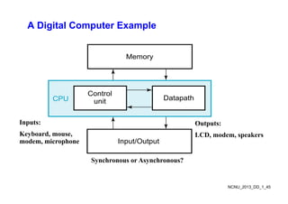
A Digital ComputerExample
Memory
Memory
Control
unit Datapath
CPU
Inputs: Outputs:
unit
p
Keyboard, mouse,
modem, microphone
Outputs:
LCD, modem, speakers
Input/Output
Synchronous or Asynchronous?
NCNU_2013_DD_1_45
46.
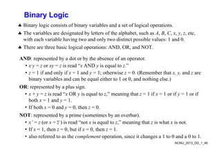
Binary Logic
Binarylogic consists of binary variables and a set of logical operations
Binary logic consists of binary variables and a set of logical operations.
The variables are designated by letters of the alphabet, such as A, B, C, x, y, z, etc,
with each variable having two and only two distinct possible values: 1 and 0.
There are three basic logical operations: AND, OR, and NOT.
AND: represented by a dot or by the absence of an operator.
N p y y p
• x·y = z or xy = z is read “x AND y is equal to z.”
• z = 1 if and only if x = 1 and y = 1; otherwise z = 0. (Remember that x, y, and z are
bi i bl d b l ith t 1 0 d thi l )
binary variables and can be equal either to 1 or 0, and nothing else.)
OR: represented by a plus sign.
• x + y = z is read “x OR y is equal to z,” meaning that z = 1 if x = 1 or if y = 1 or if
y O y q , g y
both x = 1 and y = 1.
• If both x = 0 and y = 0, then z = 0.
NOT d b i ( i b b )
NOT: represented by a prime (sometimes by an overbar).
• x’ = z (or x = z ) is read “not x is equal to z,” meaning that z is what x is not.
• If x = 1, then z = 0, but if x = 0, then z = 1.
NCNU_2013_DD_1_46
, , ,
• also referred to as the complement operation, since it changes a 1 to 0 and a 0 to 1.
47.
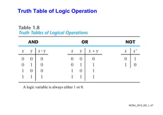
Truth Table ofLogic Operation
A logic variable is always either 1 or 0.
NCNU_2013_DD_1_47
48.
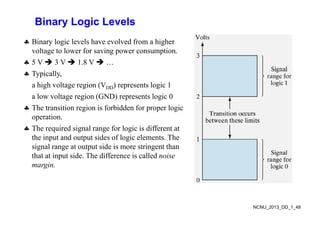
Binary Logic Levels
Binary logic levels have evolved from a higher
voltage to lower for saving power consumption.
5 V 3 V 1 8 V
5 V 3 V 1.8 V …
Typically,
a high voltage region (VDD) represents logic 1
a high voltage region (VDD) represents logic 1
a low voltage region (GND) represents logic 0
The transition region is forbidden for proper logic
operation.
The required signal range for logic is different at
the input and output sides of logic elements The
the input and output sides of logic elements. The
signal range at output side is more stringent than
that at input side. The difference is called noise
margin
margin.
NCNU_2013_DD_1_48
49.
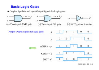
Basic Logic Gates
Graphic Symbols and Input Output Signals for Logic gates:
Graphic Symbols and Input-Output Signals for Logic gates:
Input-Output signals for logic gates
NCNU_2013_DD_1_49
50.
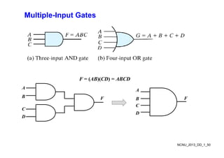
Multiple-Input Gates
F =(AB)(CD) = ABCD
F = (AB)(CD) = ABCD
A
B F
A
F
B
C
F B
C
D
F
D
NCNU_2013_DD_1_50
51.
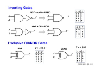
Inverting Gates
A BF
NOT + AND = NAND
A F F
A
B
A B F
0 0 1
0 1 1
1 0 1
NOT + OR = NOR
B B 1 1 0
A B F
NOT OR NOR
A
B
F A
B
F
A B F
0 0 1
0 1 0
1 0 0
1 1 0
Exclusive OR/NOR Gates
Exclusive OR/NOR Gates
A B F
XOR XNOR
F = A B F = A B
A
B
A
B
F
F
A B F
0 0 0
0 1 1
1 0 1
A B F
0 0 1
0 1 0
1 0 0
NCNU_2013_DD_1_51
1 0 1
1 1 0
1 0 0
1 1 1

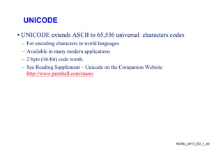
![General-purpose Digital Computer
• The major parts of a computer are a memory unit, a central processing unit (CPU), and
input–output units (I/O). [check these in your Computer course]
M it t ll i t t t d i t di t d t
• Memory unit stores programs as well as input, output, and intermediate data.
• CPU performs arithmetic and dataprocessing operations as specified by the program.
• The program and data prepared by a user are transferred into memory by means of an
The program and data prepared by a user are transferred into memory by means of an
input device such as a keyboard.
• An output device, such as a printer, receives the results of the computations, and the
i d l d h
printed results are presented to the user.
• Voice, image, finger touch, gesture, brain wave, …, also can be used as input or output.
• Communication unit provides interaction with other users through the Internet
• Communication unit provides interaction with other users through the Internet.
• A digital computer can perform not only arithmetic computations and logical operations
but also can make decisions based on internal and external conditions.
NCNU_2013_DD_1_4](https://image.slidesharecdn.com/digitalsystemsbinarynumbers-250812014629-52513c1a/85/Digital-Systems-Binary-Numbers-comprehensive-4-320.jpg)
![Hardware Description Language (HDL)
• A digital system is an interconnection of digital modules.
• To understand the operation of each digital module, it is necessary to have a basic
k l d f di it l i it d th i l i l f ti
knowledge of digital circuits and their logical function.
• A major trend in digital design methodology is the use of a hardware description
language (HDL) to describe and simulate the functionality of a digital circuit.
g g ( ) y g
• An HDL resembles a programming language and is suitable for describing digital
circuits in textual form, simulating a digital system to verify its operation before
hardware is built and automating the design process in conjunction with logic synthesis
hardware is built, and automating the design process in conjunction with logic synthesis
tools.
• Ignorance of industry’s practices on HDL modeling will lead to cute, but worthless,
HDL models that may simulate a phenomenon, but that cannot be synthesized by design
tools, or to models that waste silicon area or synthesize to hardware that cannot operate
correctly. [take the Digital System Design course for more learning on HDL]
y [ g y g g ]
NCNU_2013_DD_1_5](https://image.slidesharecdn.com/digitalsystemsbinarynumbers-250812014629-52513c1a/85/Digital-Systems-Binary-Numbers-comprehensive-5-320.jpg)
![Complements of Numbers
■ Radix Complement
The r's complement of an n-digit number N in base r is defined as rn – N for N ≠ 0
and as 0 for N = 0 Comparing with the (r 1) 's complement we note that the r's
and as 0 for N 0. Comparing with the (r 1) s complement, we note that the r s
complement is obtained by adding 1 to the (r 1) 's complement, since rn – N =
[(rn 1) – N] + 1.
Example: Base-10
The 10's complement of 012398 is 987602
Th 10' l t f 246700 i 753300
The 10's complement of 246700 is 753300
Example: Base-2
The 2's complement of 1101100 is 0010100
The 2's complement of 0110111 is 1001001
NCNU_2013_DD_1_20](https://image.slidesharecdn.com/digitalsystemsbinarynumbers-250812014629-52513c1a/85/Digital-Systems-Binary-Numbers-comprehensive-20-320.jpg)