Download as PDF, PPTX
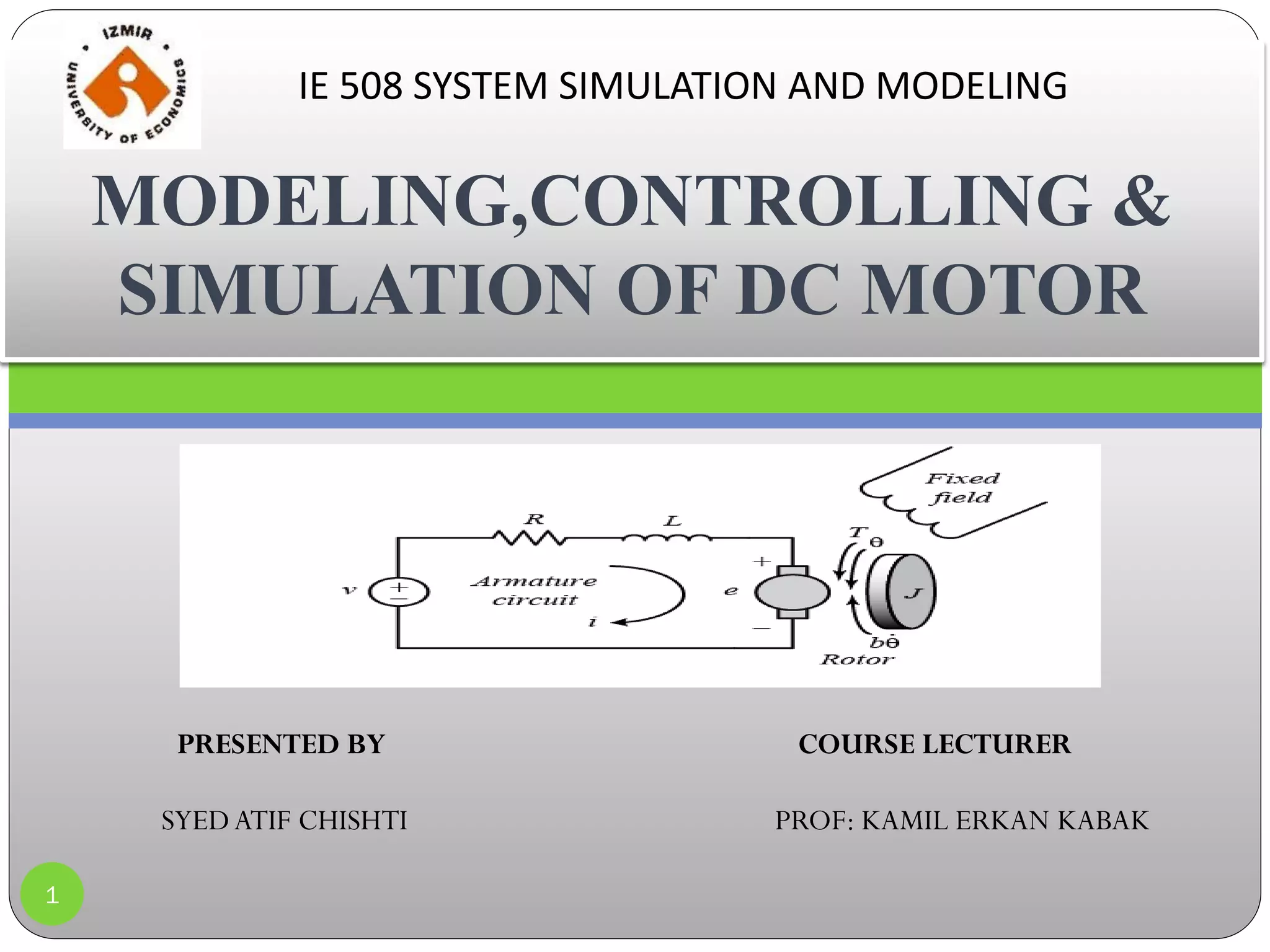
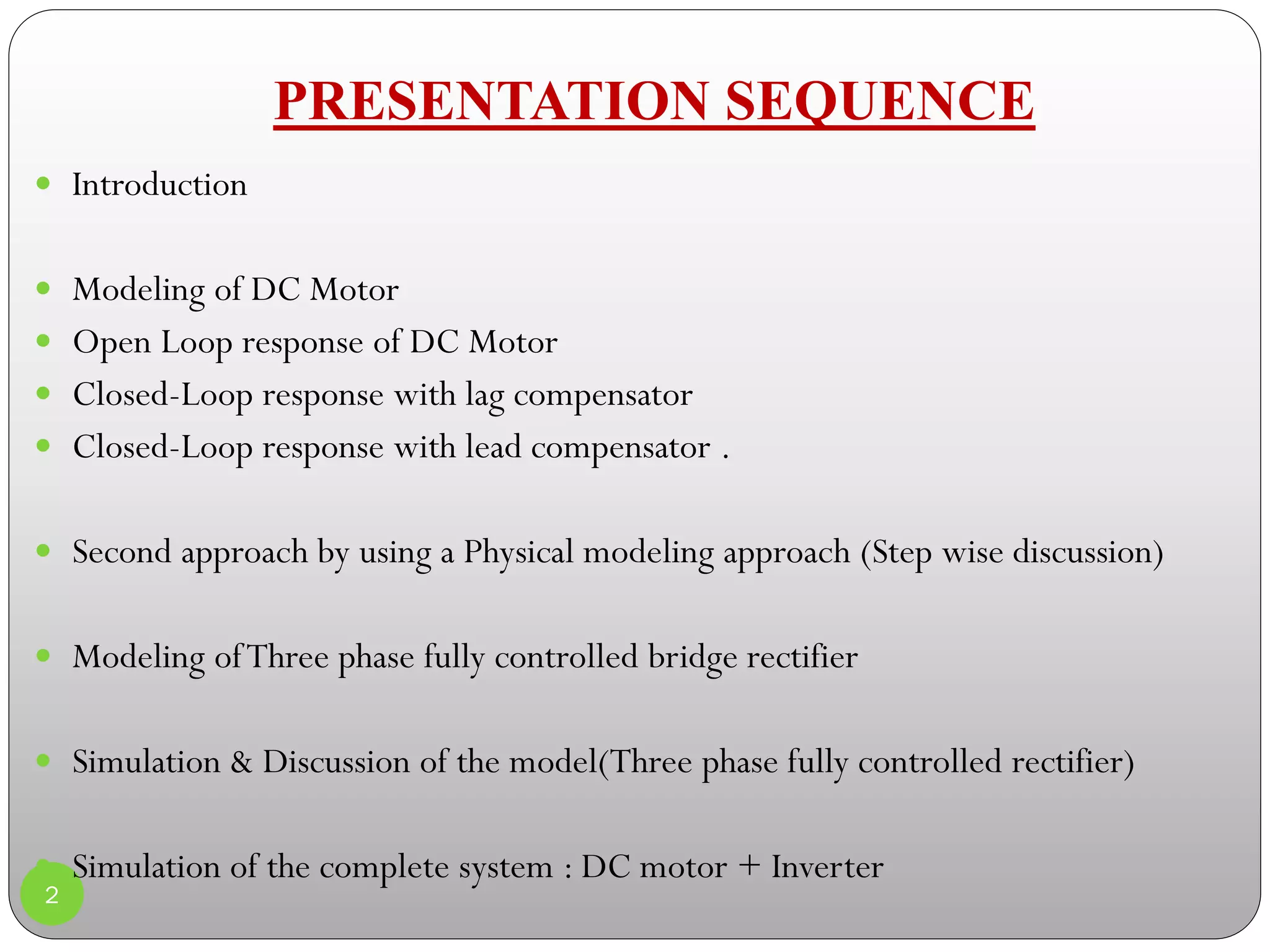
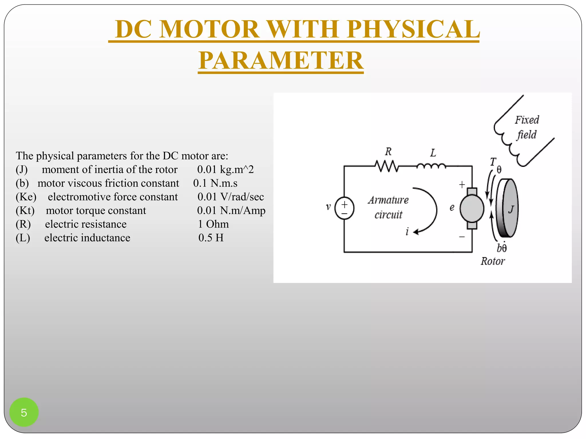
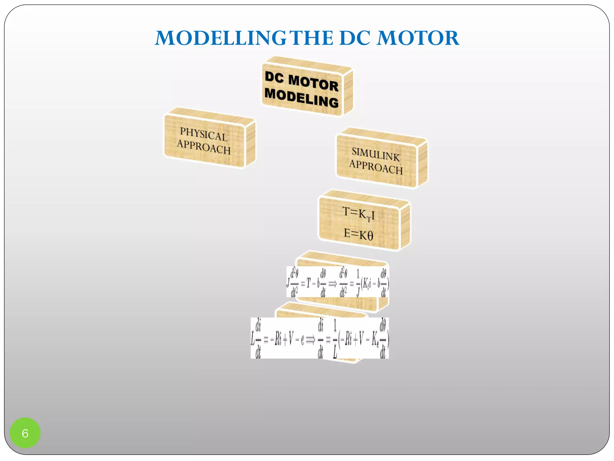
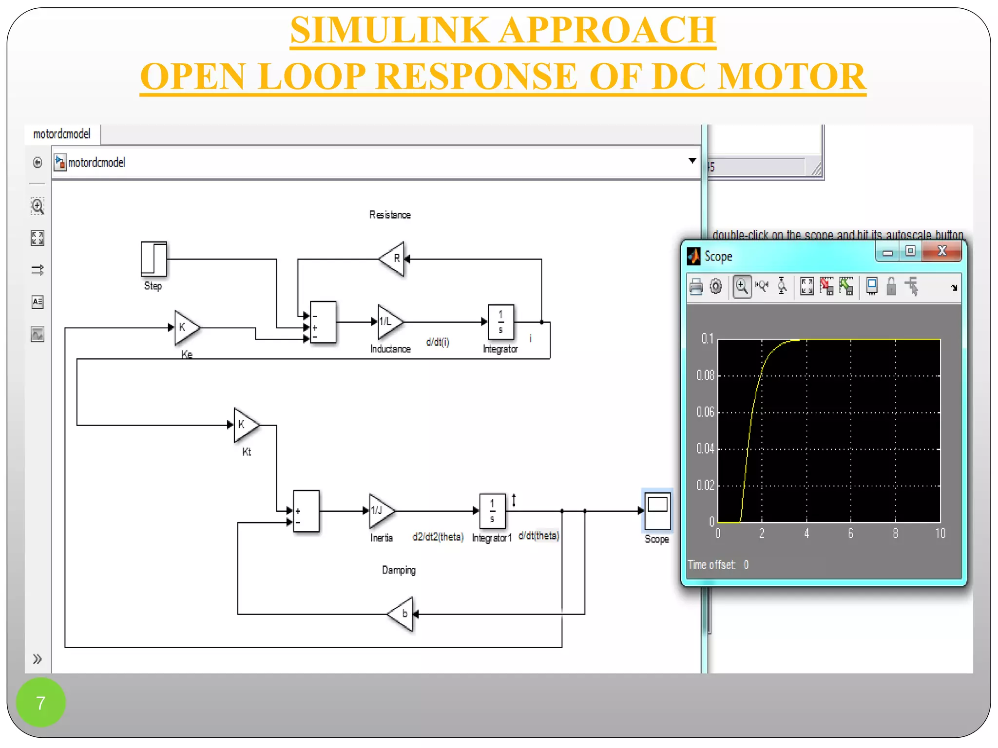
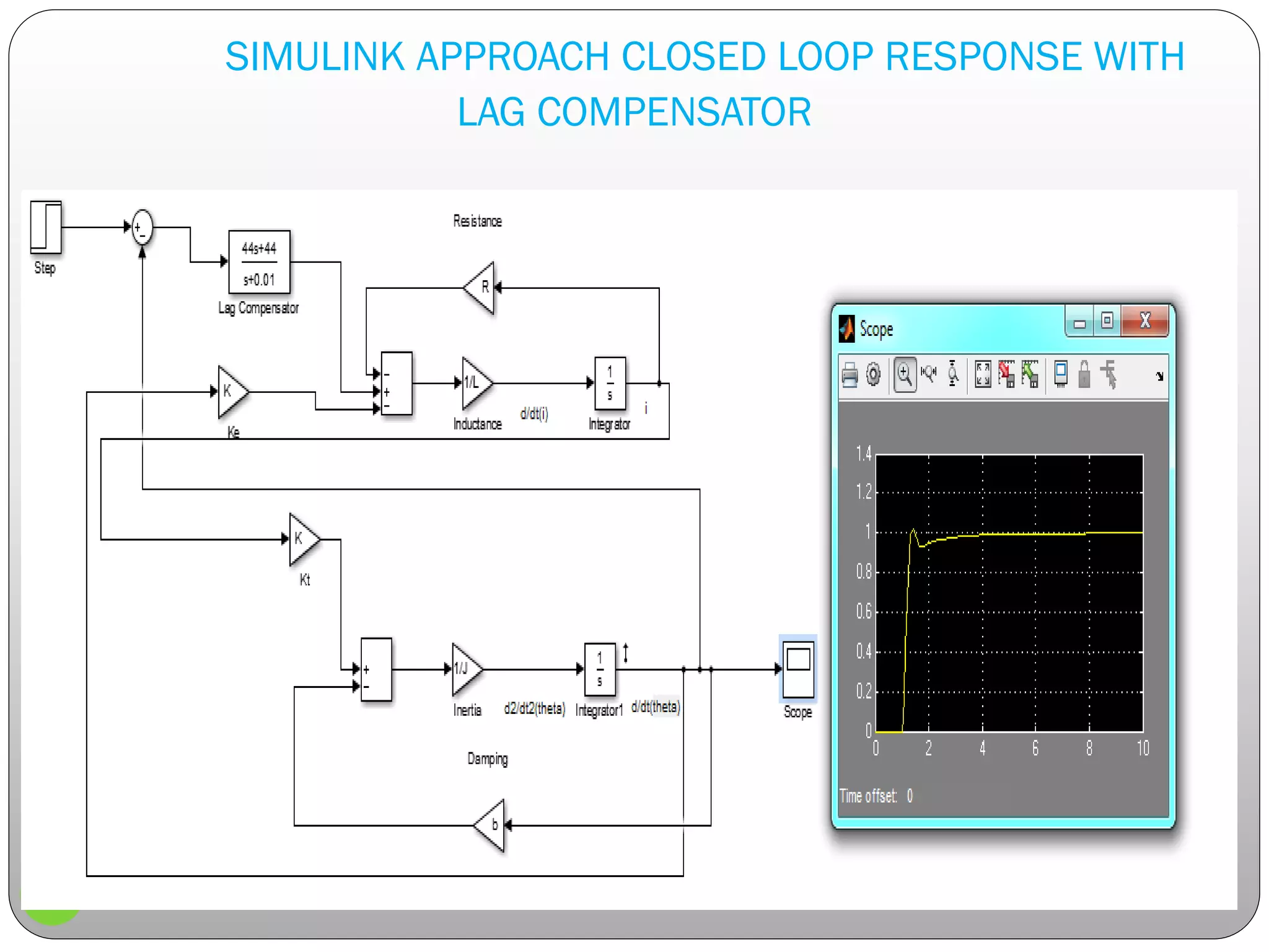
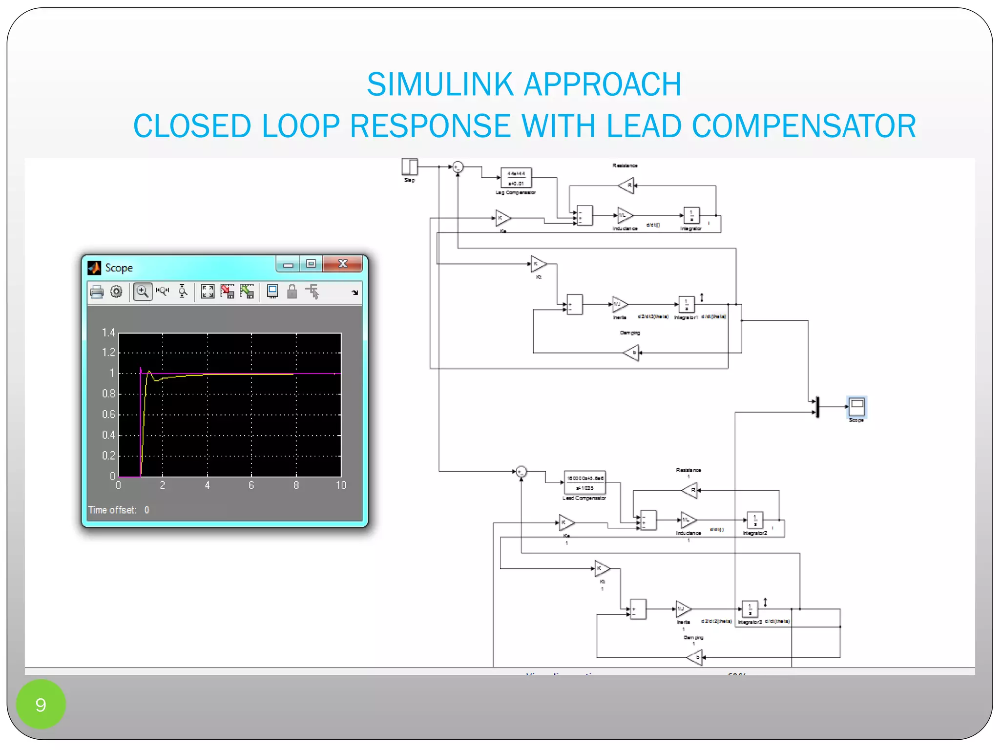
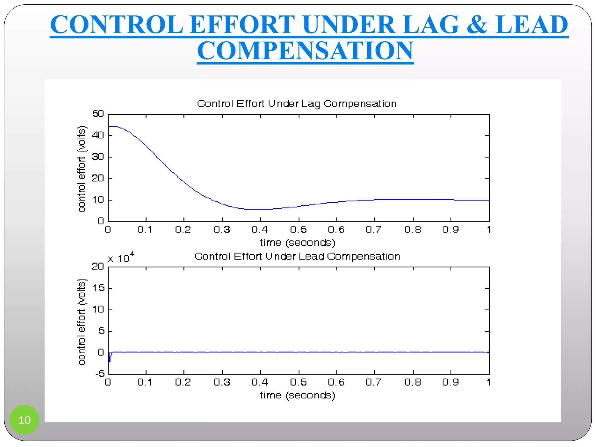
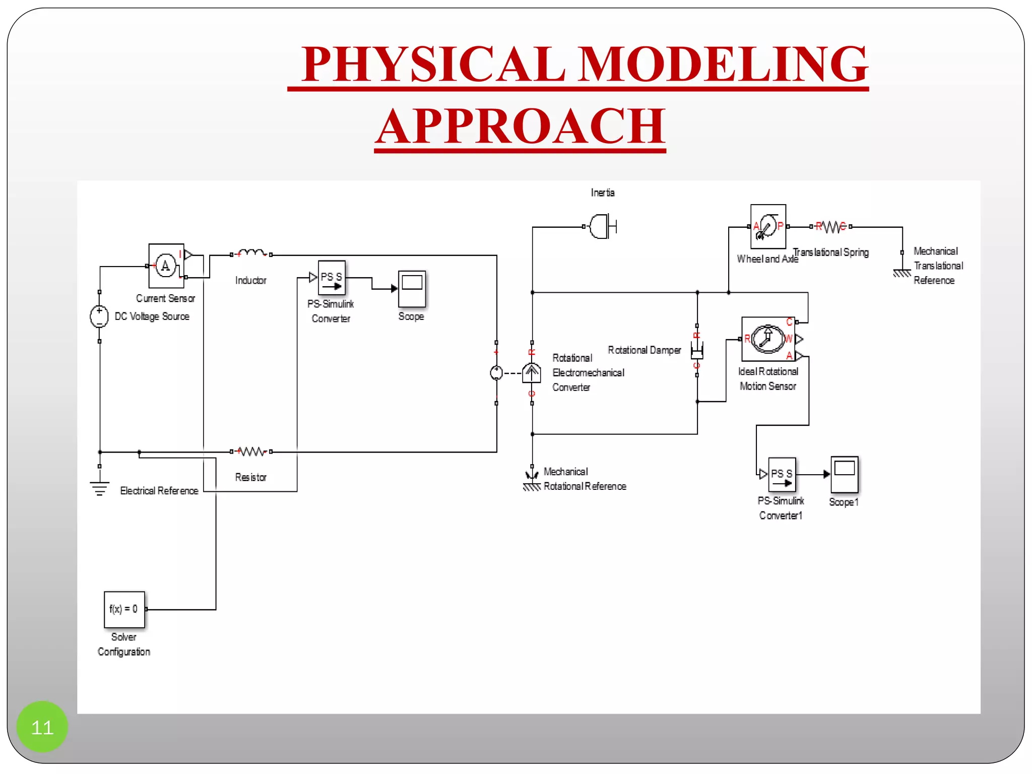
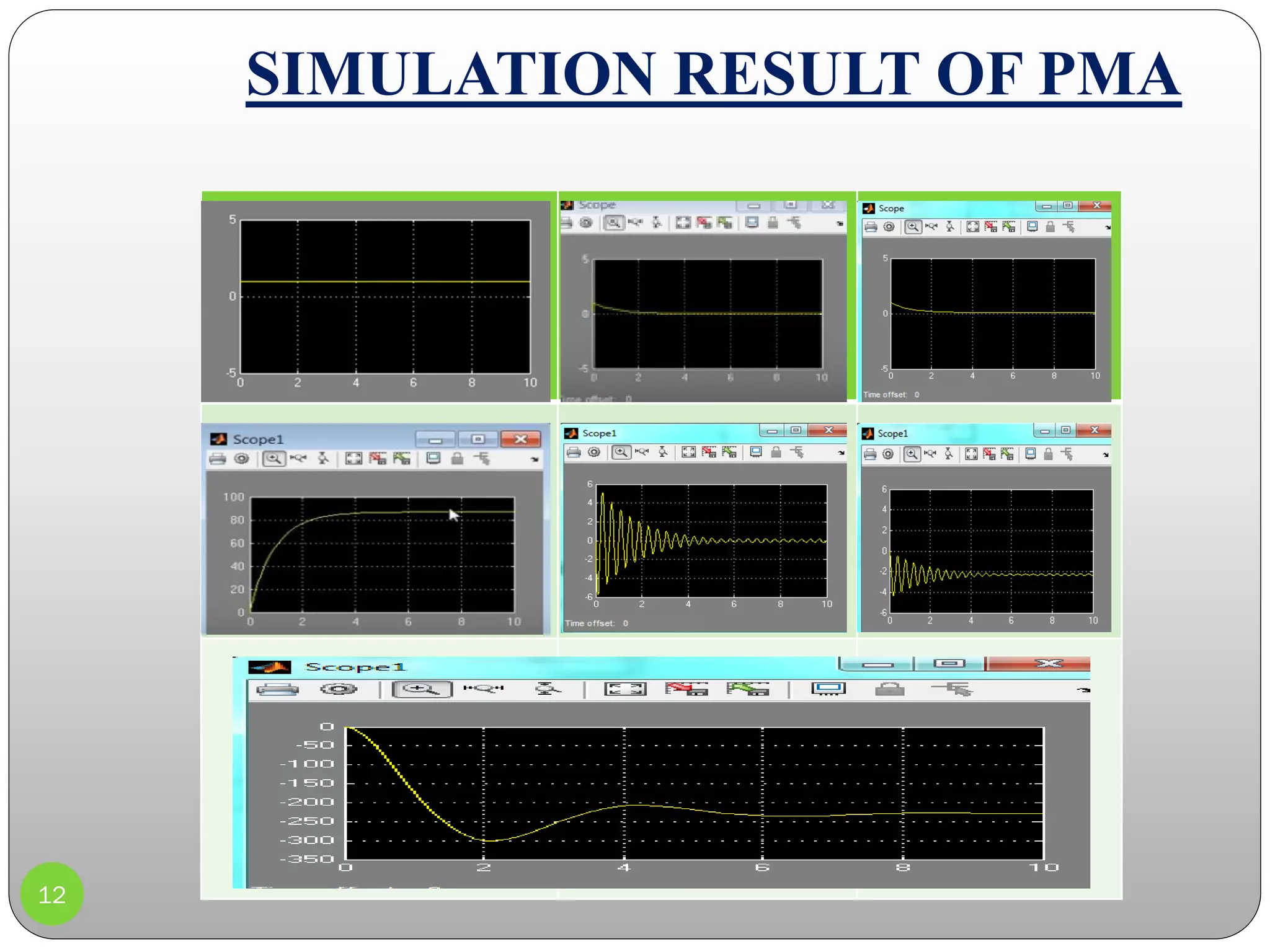
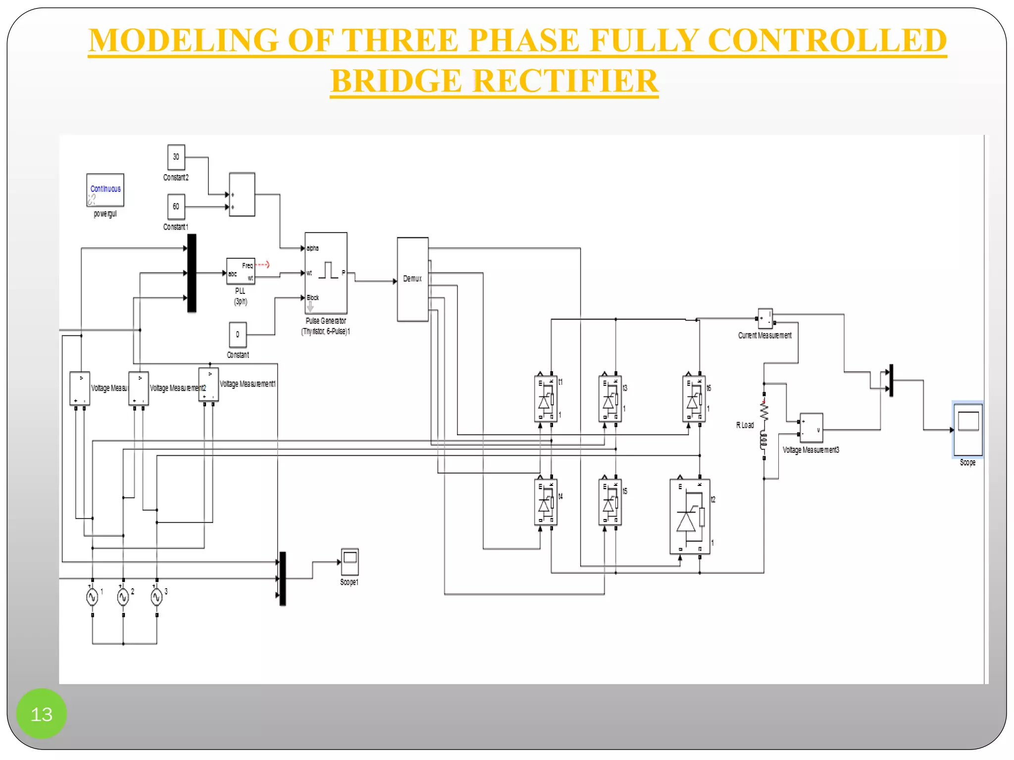
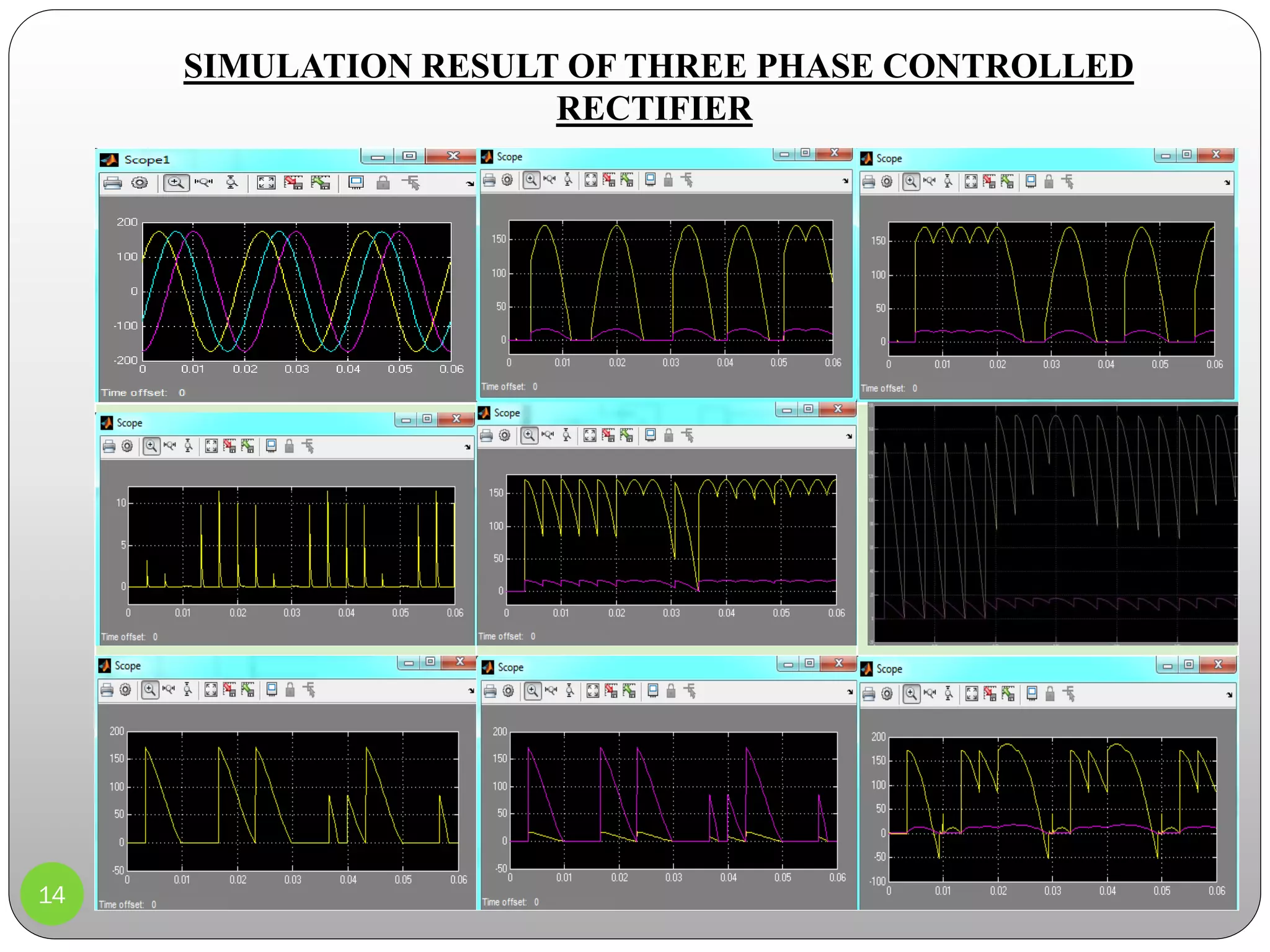
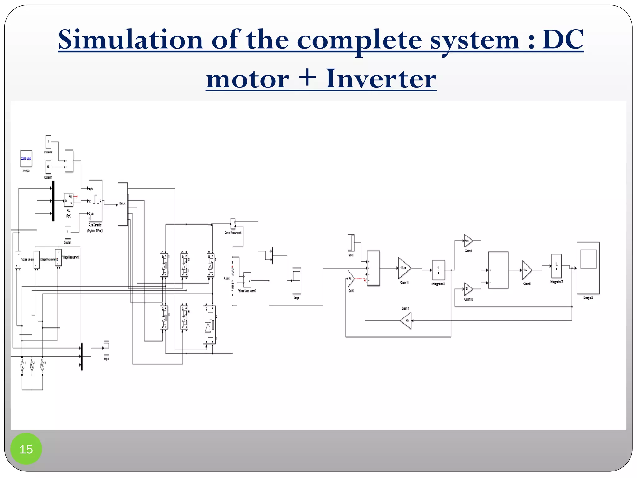
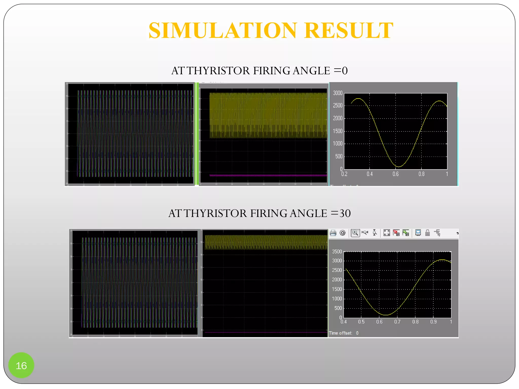
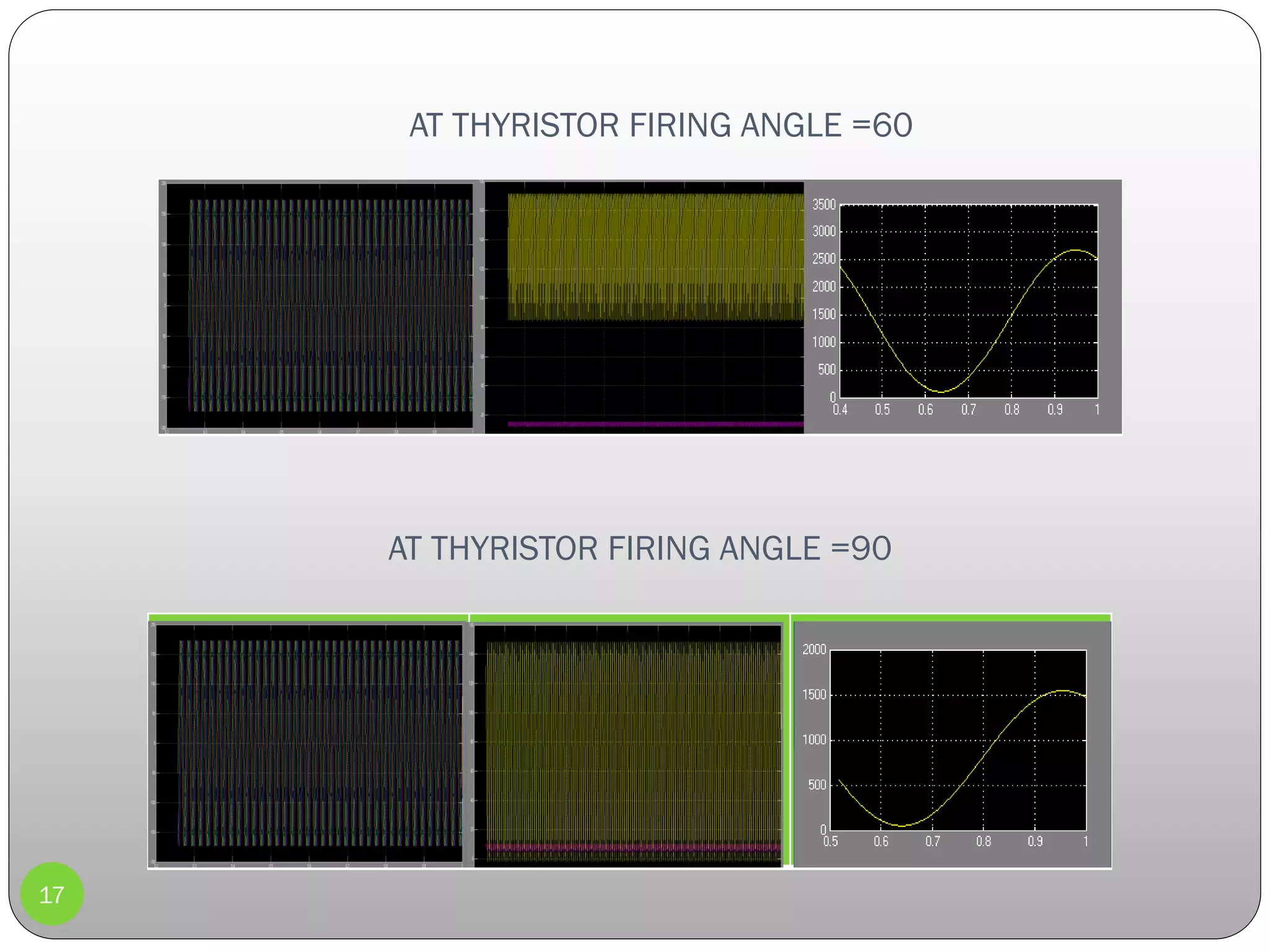


This document outlines a presentation on modeling, controlling, and simulating a DC motor. It discusses modeling the DC motor using physical parameters and in Simulink. It then examines the open and closed-loop response of the DC motor with lag and lead compensators. The document also covers modeling a three-phase fully controlled bridge rectifier and simulating the complete system of the DC motor and inverter. Key steps discussed include introducing the topic, modeling the DC motor in multiple ways, simulating the response under open and closed-loop control, modeling the rectifier, and simulating the overall system performance under different firing angles.