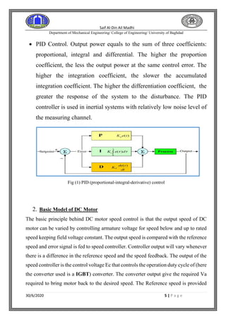
This document discusses nonlinear integral control for DC motor speed control with unknown and variable external torque. It begins with an introduction to DC motors and common speed control techniques. It then provides the basic model of a DC motor and derives the transfer function. It discusses nonlinear control systems and elements like saturation, deadband, and friction. It describes methods for solving nonlinear transient responses, nonlinear system stability, and provides a Simulink model example comparing PI and P controller performance for speed and error. References for DC motor speed control and optimization of PI controllers are also provided.
![Saif Al-Din Ail Madhi
Department of Mechanical Engineering/ College of Engineering/ University of Baghdad
30/6/2020 7 | P a g e
Td = Jdω/dt + TL --------- (i)
Taking field flux as Φ and (Back EMF Constant) Kv as K. Equation for back emf of motor
will be:
Eg = K Φ ω --------- (ii)
Also, Td = K Φ Ia --------- (iii)
From motor’s basic armature equation, after taking Laplace Transform on both sides, we will
get: Ia(S) = (Va – Eg)/(Ra + LaS)
Now, taking equation (ii) into consideration, we have:
=> Ia(s) = (Va – KΦω)/ Ra(1+ LaS/Ra )
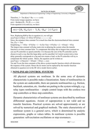
And, ω(s) = (Td - TL )/JS = (KΦIa - TL ) /JS
Also, The armature time constant will be given by:
(Armature Time Constant) Ta = La/Ra
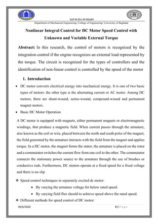
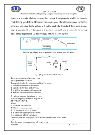
Fig (4) Model of Separately Excited DC Motor
After simplifying the above motor model, the overall transfer function will be as given
below:
ω (s) / Va(s) = [KΦ /Ra] /JS(1+TaS) /[ 1 +(K²Φ² /Ra) /JS(1+TaS)]
Further simplifying the above transfer function will yield:
ω(s) /Va(s) = (1 /kΦ) /{ 1 +(k²Φ² /Ra) /JS(1+TaS)} ---------------- (iv)
Assuming, Tm = JRa / (kΦ) ² as electromechanical time constant [1]. Then the above
transfer function can be written as below:
ω(s)/Va(s) = (1/kΦ)/ [STm (1+STa)+1] --------(v)
Let us assume that during starting of motor, load torque TL = 0 and applying full voltage Va
Also assuming negligible armature inductance, the basic armature equation can be written as:
Va = KΦω(t) + IaRa
At the same time Torque equation will be:
Td = Jdω/dt = KΦIa ----- (vi)
Putting the value of Ia in above armature equation:
Va=KΦω(t)+(Jdω/dt)Ra/ KΦ
Dividing on both sides by KΦ,
Va/KΦ=ω(t)+JRa(dω/dt)/(KΦ)² ------------------------(vii)
Va/KΦ is the value of motor speed under no load condition.
Therefore,
ω(no load)=ω(t)+JRa(dω/dt)/(KΦ)² = ω (t) + Tm (dω/dt)
Where, KΦ = Km(say) And, Tm=JRa/(KΦ)²=JRa/(Km)²](https://image.slidesharecdn.com/nonlinearintegralcontrolfordcmotorspeedcontrolwithunknownandvariableexternaltorque-210217100241/85/Nonlinear-integral-control-for-dc-motor-speed-control-with-unknown-and-variable-external-torque-7-320.jpg)