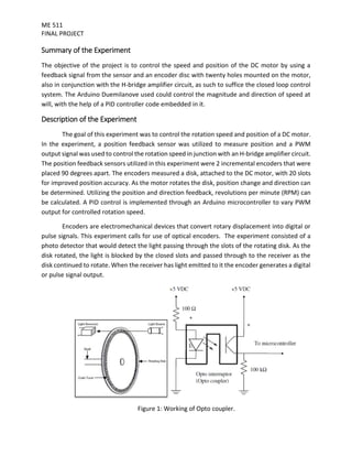
Inbuilt Digital Weighing System Inside Travel BagMOHAMMAD TANVEER
This is the ppt that we made to present our idea of "Inbuilt Weighing System Inside Travel Bag" in techFest'21 at Sant Longowal Institute Of Engineering And Technology (Deemed University), Punjab, India.
DC MOTOR SPEED CONTROL USING ON-OFF CONTROLLER BY PIC16F877A MICROCONTROLLERTridib Bose
This presentation consists the speed control of a dc motor using hardware (microcontroller) by changing the reference voltages logically and minimising errors.
Design and Implementation of an Electrical Lift Controlled using PLC IJECEIAES
This paper represents the possibility of controlling an electrical elevator model using PLC and studying some parameters to ensure its work, this model have been designed and constructed to perform a completed elevator work in an automating technique according to its programming and controlling method that making the connecting much more easier and safer than real relays and complicated wiring method. As well as the small DC motor drive (gear box) electrical motor that used to drive the elevator cabinet which made the transition from floor to floor much smoother and much efficient than the traditional elevators.
BIDIRECTIONAL SPEED CONTROL OF DC MOTOR USING 8051 MICROCONTROLLERShanmukha S. Potti
1. This project deals with bidirectional speed control of DC motor using 8051 micro-controller.
2. Design of H bridge dc-dc converter is an IGBT based bridge circuit.
3. The control circuit consists of the 8051 microcontroller which is programmed to generate pulses to turn on IGBTs per required sequence.
4. The H bridge dc-dc converter is implemented with hardware setup and software program in the 8051 –C code.
International Journal of Engineering Research and Applications (IJERA) is an open access online peer reviewed international journal that publishes research and review articles in the fields of Computer Science, Neural Networks, Electrical Engineering, Software Engineering, Information Technology, Mechanical Engineering, Chemical Engineering, Plastic Engineering, Food Technology, Textile Engineering, Nano Technology & science, Power Electronics, Electronics & Communication Engineering, Computational mathematics, Image processing, Civil Engineering, Structural Engineering, Environmental Engineering, VLSI Testing & Low Power VLSI Design etc.
Joint control of a robotic arm using particle swarm optimization based H2/H∞ ...TELKOMNIKA JOURNAL
This paper proposes a small structure of robust controller to control robotic arm’s joints where exist some uncertainties and unmodelled dynamics. Robotic arm is widely used now in the era of Industry 4.0. Nevertheless, the cost for an industry to migrate from a conventional automatic machine to industrial robot still very high. This become a significant challenge to middle or small size industry. Development of a low cost industrial robotic arm can be one of good solutions for them. However, a low-cost manipulator can bring more uncertainties. There might be exist more unmodelled dynamic in a low-cost system. A good controller to overcome such uncertainties and unmodelled dynamics is robust controller. A low-cost robotic arm might use small or medium size embedded controller such as Arduino. Therefore, the control algorithm should be a small order of controller. The synthesized controller was tested using MATLAB and then implemented on the real hardware to control a robotic manipulator. Both the simulation and the experiment showed that the proposed controller performed satisfactory results. It can control the joint position to the desired position even in the presence of uncertainties such as unmodelled dynamics and variation of loads or manipulator poses.
The main objective of capstone project is to design and develop a stable flying drone as a model
for general purposes that can be used for deliveries. The drone should be able to support lifting a
phone or similar weight, and some minor modifications should be applied to it. The drone could
be replaced in such a way that would fit any other application. I started the introduction of my
report by defining what a quadcopter is, simply because my drone’s flying system will be in that
form in which a brushless motor will be inserted in each arm. As for the control part, I will be
using a remote controller in which a transmitter will be inserted inside that would communicate
the receiver placed in the drone.
IJRET : International Journal of Research in Engineering and Technology is an international peer reviewed, online journal published by eSAT Publishing House for the enhancement of research in various disciplines of Engineering and Technology. The aim and scope of the journal is to provide an academic medium and an important reference for the advancement and dissemination of research results that support high-level learning, teaching and research in the fields of Engineering and Technology. We bring together Scientists, Academician, Field Engineers, Scholars and Students of related fields of Engineering and Technology.
Power optimisation scheme of induction motor using FLC for electric vehicleAsoka Technologies
In electric vehicles (EVs) and hybrid EVs, energy efficiency is essential where the energy storage is limited. Adding to its high stability and low cost, the induction motor efficiency improves with loss minimisation. Also, it can consume more power than the actual need to perform its working when it is operating in less than full load condition. This study proposes a control strategy based on the fuzzy logic control (FLC) for EV applications. FLC controller can improve the starting current amplitude and saves more power. Through the MATLAB/SIMULINK software package, the performance of this control was verified through simulation. As compared with the conventional proportional integral derivative controller, the simulation schemes show good, high-performance results in time-domain response and rapid rejection of system-affected disturbance. Therefore, the core losses of the induction motor are greatly reduced, and in this way improves the efficiency of the driving system. Finally, the suggested control system is validated by the experimental results obtained in the authors’ laboratory, which are in good agreement with the simulation results.
Speed Control of Brushless Dc Motor Using Fuzzy Logic Controlleriosrjce
This paper presents a control scheme of a fuzzy logic for the brushless direct current (BLDC)
permanent magnet motor drives. The mathematical model of BLDC motor and fuzzy logic algorithm is derived.
The controller is designed to tracks variations of speed references and stabilizes the output speed during load
variations. The BLDC has some advantages compare to the others type of motors, however the nonlinearity of
the BLDC motor drive characteristics, because it is difficult to handle by using conventional proportionalintegral
(PI) controller. The BLDC motor is fed from the inverter where the rotor position and current
controller is the input. In order to overcome this main problem, the fuzzy logic control is learned continuously
and gradually becomes the main effective control. The effectiveness of the proposed method is verified by
develop simulation model in MATLAB-Simulink program. The simulation results show that the proposed fuzzy
logic controller (FLC) produce significant improvement control performance compare to the PI controller for
both condition controlling speed reference variations and load disturbance variations. Fuzzy logic is introduced
in order to suppressing the chattering and enhancing the robustness of the controlled system. Fuzzy boundary
layer is developed to provide smother transition to the equivalent control. Smaller overshoot in the speed
response and much better disturbance rejecting capabilities.
For Induction motor is a system that works at their speed, nevertheless there are applications at which the speed operations are needed. The control of range of speed of induction motor techniques is available. The robust control is used with induction motor and the performance of the system with the controller will be improved. The mathematical model to the controller, which were coded in MATLAB. The modeling and controller will be shown by the conditions of robustness of be less than one.
Reviews of Cascade Control of Dc Motor with Advance Controllerijsrd.com
The proportional- integral-derivative (PID) control is the most used algorithm to regulate the armature current and speed of cascade Control system in motor drives. The controller uses two PID controllers. One PI controller is for speed control and second PID controller for current control in cascade structure. Inner loop is for the current control which is faster than the outer loop. Outer loop is for speed control. The output of the encoder is compared with a preset reference speed. The output of the PI controller is summed and is given as the input to the current controller.
TORQUE CONTROL OF AC MOTOR WITH FOPID CONTROLLER BASED ON FUZZY NEURAL ALGORITHMijics
Nowadays in the complicated systems, design of proper and implementable controller has a most importance. With respect to ability of fractional order systems in complicated systems identification as a first order fractional system with time delay, usage of fractional order PID has a proper result. From one side flexibility of fractional calculus than integer order has been topics of interest to the researchers. From another side, PMSM motors which are one the AC motor types, has been allocated largely accounted position in industry and used in variety applications. Therefore in this paper torque direct control of PMSM motors with FOPID based on model is proposed. Also fuzzy neural controllers are widely considered. Reason of this is success of fuzzy neural controller in control and identification of uncertain and complicated systems. The proposed method in this paper is combination of FOPID controller with fuzzy neural supervision system which with coefficients setting of this controller, control operation of PMSM will improve. Results of proposed method show the ability of proposed technique in reference signal tracking, elimination of disturbances effects and functional robustness in presence of noise and uncertainty. The results show the error averagely in three condition, nominal form, step disturbance and noise and uncertainly will decrease 11.66% in proposed method (FNFOPID) with Integral Square Error criterion and 7.69% with Integral Absolute Error criterion in comparison to FOPID.
Three-phase ac motors have been the workhorse of industry since the earliest days of electrical engineering. They are reliable, efficient, cost-effective and need little or no maintenance. In addition, ac motors such as induction and reluctance motors need no electrical connection to the rotor, so can easily be made flameproof for use in hazardous environments such as in mines.
In order to provide proper speed control of an ac motor, it is necessary to supply the motor with a three phase supply of which both the voltage and the frequency can be varied. Such a supply will create a variable speed rotating field in the stator that will allow the rotor to rotate at the required speed with low slip. This ac motor drive can efficiently provide full torque from zero speed to full speed, can overspeed if necessary, and can, by changing phase rotation, easily provide bi-directional operation of the motor. A drive with these characteristics is known as a PWM (Pulse Width Modulated) motor drive.
Drives and motors are an integral part of industrial equipment from packaging,robotics, computer numerical control (CNC), machine tools, industrial pumps,and fans. Designing next-generation drive systems to lower operating costs requires complex control algorithms at very low latencies as well as a flexibleplatform to support changing needs and the ability to design multiple-axis systems.
Traditional drive systems based on ASICs, digital signal processors (DSPs), and microcontroller units lack the performance and flexibility to address these needs. Altera’s family of FPGAs provides a scalable platform that can be used to offload control algorithm elements in hardware. You may also integrate the whole drive system with industry-proven processor architectures while supporting multipletypes of encoders and industrial Ethernet protocols. This “drive on a chip” system reduces cost and simplifies development.
Research Inventy : International Journal of Engineering and Scienceinventy
Research Inventy : International Journal of Engineering and Science is published by the group of young academic and industrial researchers with 12 Issues per year. It is an online as well as print version open access journal that provides rapid publication (monthly) of articles in all areas of the subject such as: civil, mechanical, chemical, electronic and computer engineering as well as production and information technology. The Journal welcomes the submission of manuscripts that meet the general criteria of significance and scientific excellence. Papers will be published by rapid process within 20 days after acceptance and peer review process takes only 7 days. All articles published in Research Inventy will be peer-reviewed.
Efficient bridgeless SEPIC converter fed PMBLDC motor using artificial neural...IJECEIAES
In this paper, a new design of Bridgeless SEPIC (Single Ended Primary Inductance converter) with Artificial neural network (ANN) fed PMBLDC Motor drive is proposed to improve Power Factor. The proposed converter has single switching device of MOSFET, so the switching losses is reduced.ANN is used to achieve the higher power factor and fixed dc link voltage. Also the ANN methodology the time taken for computation is less since there is no mathematical model. The output voltage depends on the switching frequency of the MOSFET. The BLSEPIC act as a buck operation in continuous conduction mode. Detailed converter analysis, equivalent circuit and closed-loop analysis are presented for 36V, 120W, 1500rpm BLDC Motor drive. This proposed converter produces low conduction loss, low total harmonic reduction, low settling time and high power factor reaching near-unity. All the simulation work is verified with MATLAB – Simulink.
Temperature based fan speed control & monitoring usingJagannath Dutta
Our object of making this project is for reducing the power consumption. And also to assist people who are disabled and are unable to control the speed of fan.
Implementation of Linear Controller for a DC-DC Forward Converterijceronline
This paper discusses the controller implementation of a DC to DC Forward converter. The open loop response is obtained initially. Then the closed loop control is given in real time for the Forward converter. The MATLAB interfacing is done with the help of data acquisition card. The conventional PI controller is used for the closed loop control and the results are analyzed under MATLAB/SIMULINK environment
Development of an electronic control unit for fuel injection of an ic engineeSAT Journals
Abstract Injection of the fuel into the manifold of gasoline engines has become very common. Through the concept is not new, the advent of cost effective, compact and reliable electronic controls has a lot to do with the success of fuel injection in gasoline engines. Electronics has begun to play a key role in fuel management and ignition. The modern internal combustion has to meet extreme requirements of high power to weight ratio, low exhaust emission levels and high thermal efficiency. The precise control of the ignition timing, which is possible by electronic means, allows reliable combustion with low cycle by cycle variations. Such systems also allow the engine to run under conditions very close to knock onset so that maximum thermal efficiency can be realized. Electronic control of the injection system allows us to select correct air fuel ratio for different operating conditions. It reduces mal-distribution between cylinders and leads to extremely low levels of exhaust emissions. Stable idling can also be achieved through the use of electronic controls. In this present work an ECU (Electronic Control Unit) hardware device is mainly developed for fuel injection control compatible with both 2-stroke and 4-stroke engines with PWM (Pulse Width Modulation) signal as input to the EFI (Electronic Fuel Injector). A slotted Optocoupler is used as the sensor for speed detection and producing the PWM signal. The EFI having solenoid controlled valve, which works on PWM signal to inject the fuel. 8051 microcontroller interfaced with the LCD to display the speed of the engine, has been used. The output PWM signals are tested with LabVIEW and the results are calibrated. Keywords: ECU, Slotted Optocoupler, Fuel Injection Circuit, LabVIEW.
Design and Implementation of an Improved Automatic DC Motor Speed
Control Systems Using Microcontroller
1Enerst Edozie,
2Eze Val Hyginus Udoka,
1Wantimba Janat
1Department of Electrical Engineering, Kampala international University, Uganda
2Department of Publication and Extension, Kampala International University, Uganda
ABSTRACT
Energy wastage is one of the major challenges that is facing the world now as there is
insufficient supply of energy and the little ones supplied was not appropriately used. This
energy wastage has made many researchers to engage more on the research to stop this
energy waste as a result of inappropriate allocation of energy to some devices even when
they don’t need it. This research work was able to design and implement an improved
automated DC Motor speed controller system using microcontroller successfully. The
software used for this research work were Fritzing software and Arduino Nano. This project
was able to improve on the working system of the DC Motors and energy was automatically
and successfully saved. The system runs entirely on Bluetooth technology which consumes
less power than other devices. The Android application is user-friendly with enhanced
Wireless communication. This design was successfully developed and implemented with 80%
accuracy. The design was able to work effectively by increasing the cutting speed when the
softness of the material decreases and as the cutting tool material becomes stronger, the
cutting speed increases. This showed that the design is effectively and efficiently developed
with less energy/power consumption which is the earnest desire of an Engineer as it reduces
cost.
Keywords: Microcontroller, Improved Automatic DC Motor, Energy, Arduino, PWM
Camera Movement Control using PID Controller in LabVIEWijtsrd
The aim of this system is to show how position of the dc motor can be controlled by using PID algorithm in LabVIEW for camera movement. Arduino microcontroller board is used to control the DC motor. L298N dual H Bridge motor driver is used to drive the DC motor and to execute the pulse width modulation PWM signal. Proportional Integral Derivative PID is the most common control algorithm used in industrial applications and other control system. DC motor will be interfaced with LabVIEW using an Arduino Uno microcontroller. The position of the DC motor will be set by creating a Graphic User Interface GUI in LabVIEW. LabVIEW GUI sends serial command to the microcontroller for driving PWM pins of the DC motor . DC motor will move by the user in LabVIEW for position control. The output is sent back to the PID controller in Uno microcontroller. PID compares the actual position of the DC motor with the desired position. In this system, PID controller is used to reduce the error and rotate the motor to the set point value for the camera movement control. Than Myint Kyi | Kyaw Zin Latt "Camera Movement Control using PID Controller in LabVIEW" Published in International Journal of Trend in Scientific Research and Development (ijtsrd), ISSN: 2456-6470, Volume-3 | Issue-5 , August 2019, URL: https://www.ijtsrd.com/papers/ijtsrd26397.pdfPaper URL: https://www.ijtsrd.com/engineering/electronics-and-communication-engineering/26397/camera-movement-control-using-pid-controller-in-labview/than-myint-kyi
Dual – MPPT Control of a Photovoltaic SystemIJTET Journal
Abstract - This paper proposes an efficient solar tracker system using a dual MPPT controller. It consists of three step DC to DC converter, which has been controlled by a microcontroller based unit. MPPT (Maximum Power Point Tracking) is used in photovoltaic system to maximize the PV array output power, irrespective of temperature, irradiation conditions and electrical characteristics of the load. The first MPPT controller is a dual axis solar tracker, which ensures optimization of the conversion of solar energy into electricity by properly orienting the PV panel in accordance with the real position of the sun to track azimuth and elevation angles. The second MPPT controller controls the duty cycle of the converter using modified Incremental Conductance algorithm to enable the PV array operate at maximum operating power at all conditions. The proposed control scheme eliminates oscillations and tracks the global maximum power point (GMPP) accurately. The simulation has been accomplished in MATLAB software.
Bi directional speed control of dc motor and stepper motor through mat lab us...eSAT Journals
Abstract In any industry speed control of an electric drive system is very critical and crucial. Every designer aims at achieving a control methodology having high degree of precision. But industry needs are ever evolving in nature. Hence it is very much essential that along with conventional speed control mechanisms we must also have simple interactive graphical based control strategies. Several algorithms/methodologies have been developed over the years to achieve speed control of motors. In this context by encompassing the usability of Mat Lab, work has been done to control the speed of stepper motor and DC motor using microcontroller. Microcontroller is programmed to achieve bi directional speed control. The main objective of this work is to develop the graphical user interface of motor control through mat Lab guide and the interface of the same with hardware via serial communication. PIC is used as the controller. Keywords— DC, PIC, μC, AC, GUI, IC
Bi directional speed control of dc motor and stepper motor through mat lab us...
final project
1. ME 511
FINAL PROJECT
FINAL PROJECT
CLOSED LOOP DC MOTOR SPEED AND POSITION
CONTROL
Group 14
Team Members:
Mohnish Puri Goswami Marcelo Sahagun
mgoswa2@uic.edu msahag2@uic.edu
UIN – 650791721 UIN – 650842319
Chandan Aralamallige Gopalakrishna Nicholas Jacobs
gchand7@uic.edu njacob6@uic.edu
UIN – 653143848 UIN – 674618859
Zhuoyuan Li
Zli219@uic.edu
UIN – 665800663
Performed on : 04/29/2016
2. ME 511
FINAL PROJECT
Summary of the Experiment
The objective of the project is to control the speed and position of the DC motor by using a
feedback signal from the sensor and an encoder disc with twenty holes mounted on the motor,
also in conjunction with the H-bridge amplifier circuit, as such to suffice the closed loop control
system. The Arduino Duemilanove used could control the magnitude and direction of speed at
will, with the help of a PID controller code embedded in it.
Description of the Experiment
The goal of this experiment was to control the rotation speed and position of a DC motor.
In the experiment, a position feedback sensor was utilized to measure position and a PWM
output signal was used to control the rotation speed in junction with an H-bridge amplifier circuit.
The position feedback sensors utilized in this experiment were 2 incremental encoders that were
placed 90 degrees apart. The encoders measured a disk, attached to the DC motor, with 20 slots
for improved position accuracy. As the motor rotates the disk, position change and direction can
be determined. Utilizing the position and direction feedback, revolutions per minute (RPM) can
be calculated. A PID control is implemented through an Arduino microcontroller to vary PWM
output for controlled rotation speed.
Encoders are electromechanical devices that convert rotary displacement into digital or
pulse signals. This experiment calls for use of optical encoders. The experiment consisted of a
photo detector that would detect the light passing through the slots of the rotating disk. As the
disk rotated, the light is blocked by the closed slots and passed through to the receiver as the
disk continued to rotate. When the receiver has light emitted to it the encoder generates a digital
or pulse signal output.
Figure 1: Working of Opto coupler.
3. ME 511
FINAL PROJECT
The encoder uses two output channels to determine position. Using two channels positioned 90°
out of phase, the two output channels of the quadrature encoder indicate both position and
direction. Monitoring both the number of pulses and the relative phase signals of both channels
the Arduino can track both the position and direction of rotation
Figure 2: Tracking on disk via two channels.
The basic method to determine the position and direction of the motor with the encoder
feedback is connecting them to interrupt coding using an interrupt service routine (ISR). A single
ISR input on the Arduino microcontroller will give the state of the interrupter change.
When the encoders are set at a 90 degree phase angle, and changes their state, the
following channel combinations are possible:
Channel A: 0 0 1 1 0 0 1 1 0 0 1 1 0 0 1 1....
Channel B: 0 1 1 0 0 1 1 0 0 1 1 0 0 1 1 0…
Encoder Directions: ← ccw or cw →
The direction is determined by the following algorithm:
if Channel A is rising (0 to 1)
if Channel B is 0, ccw
else, cw
if Channel A is falling (1 to 0)
if Channel B is 0, cw
else, ccw
if cw, increment position by 45 degrees
if ccw, decrement position by 45 degrees
Calculate velocity by using ∆angle/∆time
4. ME 511
FINAL PROJECT
The H-Bridge circuit along with the microcontroller is used to control the output signal
onto the
DC motor. The Arduino microcontroller is used to control the HIGH and LOW output signal for
rotation speed of the DC motor. The H-bridge circuit included allows the efficient control of
output current, which can be sent to control the direction of the DC Motor rotation. A DC motor
converts electrical power into mechanical power. The input of voltage and current is used to
develop torque and speed as the mechanical output. In DC Motors there are two magnetic fields
perpendicular to the current. The two types of DC motors are brush and brushless. Brush motors
have the magnetic field created when current flows into the winding of the rotor while the other
field works as design of the permanent magnets in the stator. Brushless motors have the rotor
and stator work differently, because the permanent magnets are on the rotor and the wind on
the stator.
Tm = K * Br * Bs * Sin(theta_rs)
The torque created is proportional to the strength of the two magnetic flux vectors of the stator
and rotor, and the angle between the two vectors. Depending on the direction of the current
flow, a force is generated on the conductor as a result of the interaction between the "stator
magnetic field" and the "rotor magnetic field".
F = L*ixB
This force then created a torque, by the relation
Tm = F*d
Since B, L, and d are constants; the torque is derived as a proportional relationship to current.
Tm = Kt*i
The electrical circuit relationship in the motor, considering the emf voltage is
Vt(t) = R*i(t) + L*di(t)/dt + Ke*w(t)
A PID control was implemented for a pre-programmed set position point and set rotation
speed and that determined the PWM output signal through the H-Bridge circuit. A Proportional-
Integral-Derivative (PID) control is the most common control algorithm used. The PID algorithm
consists of three basic gains. A proportional, integral and derivative are utilized to get optimal
response time. In Closed loop systems, the theory of a PID control is to read a sensor, then
compute the desired PWM output by calculating proportional, integral, and derivative responses
and summing those three gains with error to compute the desired output.
5. ME 511
FINAL PROJECT
Figure 3: Block diagram for the project circuit.
Proportional Gain Kp
The proportional gain depends the difference between the set point and the calculated output
which equals the error. It determines the ratio of output response to the error signal. Ultimately,
increasing the proportional gain will increase the speed of the control system response, but if too
large, the response will oscillate to the point the system becomes unstable. The formula for P is:
POUT = KP * KERR
The formula for KERR is:
KERR = Target Point – Current Point
POUT is the result, KP is the gain and the KERR is the error. The equation is a multiplication of the
error multiplied by gain. Increasing the gain essentially increases the response per unit of error.
Essentially, the proportional control gain has the steady state error which results in needing the
integral and derivative gains for better system control.
Figure 4: Overshoot at high value of Kp.
Integral Response Ki
The integral gain is the sum of the calculated error over time, which is integrated error. The
integral output response will increase unless steady state error is equal to zero. Steady-State
error is the calculated difference between the output response and set point. The gain Ki results
6. ME 511
FINAL PROJECT
in low percent overshoot and settling time. I output will cause an overshoot and then drive it
back. The formula for I control is:
IOUT = KI * IERR
The formula for IERR is:
IERR = Previous IERR + KERR
An issue encountered is integral error will build up rapidly and cause a rapid and unstable
reaction when system is suddenly enabled. Setting a maximum integral error is ideal to prevent
the system question from “over-responding” to an error.
Figure 5: Overshoot for Ki.
Derivative Response Kd
The derivative gain controls the output response to decrease if changed too fast. The derivative
gain is proportional to the rate of change of the process variable. The quick system change will
cause the derivative error to change and quickly change the system response. Essentially, driven
by the change of the KERR. It can be used to react to sudden changes in error, and is good for
maintaining a certain position or velocity on a closed loop system. The formula for D is:
DOUT = DERR * KD
The formula for DERR is:
DERR = KERR – Previous KERR
Figure 6: Overshoot for Kd values.
7. ME 511
FINAL PROJECT
The summation of the PID gains will ultimately be a function of time that will control the output
response of any system with great accuracy
Figure 7: PID control logic defining the percentage overshoot and settling time.
8. ME 511
FINAL PROJECT
List of Components
ITEM QUANTIY PART NO. SUPPLIER
DC Motor 1 154915 Jameco Electronics
Set of Connection
wires
1 020079 Jameco Electronics
Breadboard 1 020722 Jameco Electronics
IN4704 Zener Diode 4 35975 Jameco Electronics
IRF510 (MOSFET) 2 209234 Jameco Electronics
IRF9520 (MOSFET) 2 670629 Jameco Electronics
Opto-coupler 1 40985 Jameco Electronics
Slotted Opto-
interrupter
1 2078282 Jameco Electronics
Encoder disc 1 - Amazon
Sensor 1 2159453 Amazon
Pic Demo bread/
connector
1 DM163022 Jameco Electronics
3-D printed model 1 - Self-designed at UIC
Labs
Function Generator 1 - Mechatronics
Laboratory (UIC)
USB Cable 1 - Mechatronics
Laboratory (UIC)
Laptop 1 - Mechatronics
Laboratory (UIC)
10. ME 511
FINAL PROJECT
Figure 9: The Opto-coupler used in the circuit (where only first two opto-couplers with ports
1,2,3,4 & 13,14,15,16 were used).
11. ME 511
FINAL PROJECT
Figure 10: Group 14 Project connections which goes to the motor with the help of two thick
wires (yellow and brown).
12. ME 511
FINAL PROJECT
Figure 11: Assembly of design of the 3-D printed base.
Figure 12: Group 14 model of the 3-D printed base for mounting DC motor, sensor and encoder.
17. ME 511
FINAL PROJECT
Procedure
1. A circuit diagram for the closed loop DC motor position control using PWM (Pulse Width
Modulation) as show in the figure. In this circuit, microcontroller was able to provide position
control of a DC motor. Organize all the components, assemble DC motor and other
components on breadboard as shown in circuit diagram. In this circuit, the H-bridge is made
of four MOSFET power transistors and four diodes. And using this to drive the motor in the
required direction.
2. After building this circuit, we designed a fixture in SolidWorks which could hold the DC motor
and position sensors in it. As shown in the picture, the 3D printed fixture make our device
very neat and compact. We connected disk with several holes to the shaft of the motor, so
the disk rotates in the same speed as the shaft of DC motor.
3. When this disk is assembled in the configuration shown in pictures, the rotation of the motor
causes the beam of light to be periodically intercepted by the solid parts of the disk creating
a sequence of pulses of light, which will be translated by the sensors into pulses of electricity.
Those information provided by the pulses of electricity give us feedback signal such as the
frequency of those pulses represent speed of rotation and the number of those pulses
correspond to the angular displacement of the shaft.
4. The most important part in this project is coding. In the closed loop system, microcontroller
should constantly adjust the average power delivered to the motor to reach the required
velocity and precisely calculate the position of the motor’s output shaft. With precise
information of speed and position we can determine the PWM output base on a PID control.
5. Because H-bridge cannot control the velocity of the motor. We need controller turn the
solenoid ON and OFF at very high rates, changing the ratio between the ON and OFF time to
control the speed of the motor. This is what PWM does, by rectifying the duty cycle of the
PWM sent to motor to reach the required speed.
6. The analog Write function allows us to generate a PWM wave in Arduino. This function takes
a value between 0 and 255. The speed of the motor depends on value that was passed to the
analog Write function. The value can be between 0 and 255. If we pass 0, then the motor will
stop and if we pass 255 then it will run at full speed.
7. Then, we load our code into workspace. Program the code found in the Results section into
Arduino. The code is configured to the circuit built in Figure.
8. When we’re done with programming, we can upload it. Click the Verify button to compile the
18. ME 511
FINAL PROJECT
code. Then upload the program to the module. At last, connect circuit with DC power supply
and press the switch.
Result
Flowchart showing sequence of steps taken in the project
Purchase of
Components
Literaturereview
and building the
circuit
Designing themount
Structures
Fabrication and
assembly
Execution ofcode
and circuit
Required
components?
Design based on
Literatureand
working principle?
Tolerances match?
Operation is as
required ?
Inputfrom Lab
manual,
Textbook and
Datasheets
DATA
Collection
and I/O
through
Serial
Monitor
Conclusion and
Results
(NO)Feedback for purchase
YES
No
Feedback
YES
START
Inspection
NO
YES
Verification
NO
YES
END
19. ME 511
FINAL PROJECT
Code for Ramped Function speed, Trajectory- Vo=20, Speed=80 with ISR
int motorPin = 3;
int pwm=10;
int t;
int rpm;
int count;
int r;
int set_rpm;
int err;
int sum_err;
int old_err;
float u;
int val;
int encoder0PinA = 2;
int encoder0PinB = 9;
int encoder0Pos = 0;
int encoder0PinALast = LOW;
int n = LOW;
int x1;
int x2,x3,x4;
int encoder_avg;
int encoder_gap1;
int encoder_gap2;
int encoder_gap3;
int i;
int Vo;
20. ME 511
FINAL PROJECT
int encoder_Tar;
int z;
int speed;
int steps;
void setup()
{
pinMode (encoder0PinA,INPUT);
pinMode (encoder0PinB,INPUT);
pinMode(motorPin, OUTPUT);
pinMode(pwm, OUTPUT);
digitalWrite(pwm, LOW);
Serial.begin(9600);
while (! Serial);
Serial.println("Vo");
Serial.println("Set Initial Speed 0 to 255");
}
void loop()
{
if (Serial.available())
{
Vo = Serial.parseInt();
int speed = Serial.parseInt();
if (speed >= 0 && speed <= 255){
22. ME 511
FINAL PROJECT
n = digitalRead(encoder0PinA);
Serial.println("this is ISR2");
if ((encoder0PinALast == LOW) && (n == HIGH)) {
if (digitalRead(encoder0PinB) == LOW) {
rpm=count*0.00166667*60;
count=0;
r=speed;
set_rpm = r/10;
err= set_rpm -rpm;
sum_err +=err;
u =8.5*err + 0.5*sum_err + 7.5*(err-old_err);
old_err = err;
speed=u*1.25;
if(speed>255)
{
speed=255;
}
speed = Vo*pow(2.71,(0.25*10));// estimated rising expression of trapezoid-logarithmic model
speed= speed+Vo*pow(2.71,(0.5*2.5));
if (speed >= 0 || speed <= 255) {
Vo = -Vo ;
analogWrite(motorPin, speed);
for(i=0;i<50;i++)
{analogWrite(motorPin, speed);}
23. ME 511
FINAL PROJECT
Serial.println("good speed");
}
}
Code – Encoder counting with ISR
int motorPin = 3;
int pwm=10;
int t;
int rpm;
int count;
int r;
int set_rpm;
int err;
int sum_err;
int old_err;
float u;
int val;
int encoder0PinA = 2;
int encoder0PinB = 9;
int encoder0Pos = 0;
int encoder0PinALast = LOW;
int n = LOW;
int x1;
int x2,x3,x4;
int encoder_avg;
int encoder_gap1;
24. ME 511
FINAL PROJECT
int encoder_gap2;
int encoder_gap3;
int i;
int Vo;
int encoder_Tar;
int z;
int speed;
void setup()
{
pinMode (encoder0PinA,INPUT);
pinMode (encoder0PinB,INPUT);
pinMode(motorPin, OUTPUT);
pinMode(pwm, OUTPUT);
digitalWrite(pwm, LOW);
Serial.begin(9600);
while (! Serial);
Serial.println("Set Initial Speed 0 to 255");
}
void loop()
{
if (Serial.available())
{
// Vo = Serial.parseInt();
int speed = Serial.parseInt();
26. ME 511
FINAL PROJECT
void counting_func() {
n = digitalRead(encoder0PinA);
if ((encoder0PinALast == LOW) && (n == HIGH)) {
if (digitalRead(encoder0PinB) == LOW) {
encoder0Pos--;
} else {
encoder0Pos++;
}}
x1= encoder0Pos;
Serial.println("start");
Serial.println(x1);
if ((encoder0PinALast == HIGH) && (n == LOW)) {
if (digitalRead(encoder0PinB) == LOW) {
encoder0Pos--;
} else {
encoder0Pos++;
}}
x2= encoder0Pos;
Serial.println(x2);
if ((encoder0PinALast == HIGH) && (n == HIGH)) {
if (digitalRead(encoder0PinB) == LOW) {
encoder0Pos--;
} else {
encoder0Pos++;
}}
x3= encoder0Pos;
27. ME 511
FINAL PROJECT
Serial.println(x3);
if ((encoder0PinALast == HIGH) && (n == HIGH)) {
if (digitalRead(encoder0PinB) == LOW) {
encoder0Pos--;
} else {
encoder0Pos++;
}}
x4=encoder0Pos;
Serial.println(x4);
Serial.println("/");
encoder0PinALast = n;
encoder_avg = (x1+x2+x3+x4)/4;
Serial.print("encoder_avg_value =");
Serial.println(encoder_avg);
Serial.println("end");
}
Conclusion
The speed was determined by the value of PWM output. This function takes a value between 0
and 255. If we pass a value between 0 and 255, then the speed of the motor will vary accordingly.
And the coils were energized according to the duty cycle of PWM, Position control was achieved
by PID control and feedback signal from position sensors. We can calculate precise speed and
angle displacement of motor’s shaft base on the information provided by two position sensors.
28. ME 511
FINAL PROJECT
Reference
Cetinkunt, S. (2009). Mechatronics lab manual. Chicago, IL: Department of Mechanical and
Industrial Engineering
National semiconductor. (Oct 2005). DM163022 PIC Demo bread.
http://www.jameco.com/webapp/wcs/stores/servlet/Product_10001_10001_1281086_-
1
(Date accessed: 04/27/2016, Time 4.00pm)
Jameco Electronics : Digital sensor (Arduino compatible)
http://www.jameco.com/webapp/wcs/stores/servlet/Product_10001_10001_2159453_-
1
(Date accessed: 04/24/2016, Time 1.00pm)
Jameco Electronics : 3 Volt DC Motor-3588 rpm.
http://www.jameco.com/webapp/wcs/stores/servlet/Product_10001_10001_154915_-1
(Date accessed: 04/27/2016, Time 4.00pm)
Figure 17: Description of Motor used in the project.