This document describes modeling, simulation, and implementation of speed control for a DC motor using a PIC16F877A microcontroller. It includes:
1) Developing mathematical models for the DC motor based on torque equations and transfer functions.
2) Creating a Simulink model to simulate the motor's step and impulse responses.
3) Designing a hardware system using the PIC16F877A microcontroller to generate PWM signals to control the motor speed, along with other components like a driver circuit and optical encoder.
4) Implementing the control system and presenting results of experimental speed control at different setpoints.
Design and Implementation of an Electrical Lift Controlled using PLC IJECEIAES
This paper represents the possibility of controlling an electrical elevator model using PLC and studying some parameters to ensure its work, this model have been designed and constructed to perform a completed elevator work in an automating technique according to its programming and controlling method that making the connecting much more easier and safer than real relays and complicated wiring method. As well as the small DC motor drive (gear box) electrical motor that used to drive the elevator cabinet which made the transition from floor to floor much smoother and much efficient than the traditional elevators.
A comparative study of pi, fuzzy and hybrid pi fuzzy controller for speed con...Asoka Technologies
This paper presents the comparative study between PI, fuzzy and hybrid PI-Fuzzy controller for speed control of brushless dc (BLDC) motor. The control structure of the proposed drive system is described. The simulation results of the drive system for different operation modes are evaluated and compared. A fuzzy controller offers better speed response for start-up while PI controller has good compliance over variation of load torque but has slow settling response. Hybrid controller has an advantage of integrating a superiority of these two controllers for better control performances. Matlab/Simulink is used to carry out the simulation.
Three-phase ac motors have been the workhorse of industry since the earliest days of electrical engineering. They are reliable, efficient, cost-effective and need little or no maintenance. In addition, ac motors such as induction and reluctance motors need no electrical connection to the rotor, so can easily be made flameproof for use in hazardous environments such as in mines.
In order to provide proper speed control of an ac motor, it is necessary to supply the motor with a three phase supply of which both the voltage and the frequency can be varied. Such a supply will create a variable speed rotating field in the stator that will allow the rotor to rotate at the required speed with low slip. This ac motor drive can efficiently provide full torque from zero speed to full speed, can overspeed if necessary, and can, by changing phase rotation, easily provide bi-directional operation of the motor. A drive with these characteristics is known as a PWM (Pulse Width Modulated) motor drive.
Drives and motors are an integral part of industrial equipment from packaging,robotics, computer numerical control (CNC), machine tools, industrial pumps,and fans. Designing next-generation drive systems to lower operating costs requires complex control algorithms at very low latencies as well as a flexibleplatform to support changing needs and the ability to design multiple-axis systems.
Traditional drive systems based on ASICs, digital signal processors (DSPs), and microcontroller units lack the performance and flexibility to address these needs. Altera’s family of FPGAs provides a scalable platform that can be used to offload control algorithm elements in hardware. You may also integrate the whole drive system with industry-proven processor architectures while supporting multipletypes of encoders and industrial Ethernet protocols. This “drive on a chip” system reduces cost and simplifies development.
Speed Control of Brushless Dc Motor Using Fuzzy Logic Controlleriosrjce
This paper presents a control scheme of a fuzzy logic for the brushless direct current (BLDC)
permanent magnet motor drives. The mathematical model of BLDC motor and fuzzy logic algorithm is derived.
The controller is designed to tracks variations of speed references and stabilizes the output speed during load
variations. The BLDC has some advantages compare to the others type of motors, however the nonlinearity of
the BLDC motor drive characteristics, because it is difficult to handle by using conventional proportionalintegral
(PI) controller. The BLDC motor is fed from the inverter where the rotor position and current
controller is the input. In order to overcome this main problem, the fuzzy logic control is learned continuously
and gradually becomes the main effective control. The effectiveness of the proposed method is verified by
develop simulation model in MATLAB-Simulink program. The simulation results show that the proposed fuzzy
logic controller (FLC) produce significant improvement control performance compare to the PI controller for
both condition controlling speed reference variations and load disturbance variations. Fuzzy logic is introduced
in order to suppressing the chattering and enhancing the robustness of the controlled system. Fuzzy boundary
layer is developed to provide smother transition to the equivalent control. Smaller overshoot in the speed
response and much better disturbance rejecting capabilities.
Design of Fuzzy Logic Controller for Speed Regulation of BLDC motor using MATLABijsrd.com
Brushless DC (BLDC) motors drives are one of the electrical drives that are rapidly gaining popularity, due to their high efficiency, good dynamic response and low maintenance. The design and development of a BLDC motor drive for commercial applications is presented. The aim of paper is to design a simulation model of inverter fed PMBLDC motor with Fuzzy logic controller. Fuzzy logic controller is developed using fuzzy logic tool box which is available in Matlab. FIS editor used to create .FIS file which contains the Fuzzy Logic Membership function and Rule base. And membership functions of desired output. After creating .FIS file it is implemented in the Matlab Simulink. And the BLDC motor is run satisfactorily using the Fuzzy logic controller.
Digital Signal Controller Based Four Switch Three Phase Inverter Fed BLDC Mot...ijsrd.com
Brushless Direct Current Motors (BLDC) are used in many applications for their low cost, high performance , ease of control, less maintenance because of absence of commutators and brushes and high efficiency. These advantages of BLDC motors have led to their wide spread use in variable speed drives. The main objective of this paper is to develop a drive system for BLDC motor with reduced switches and minimum hardware. The proposed work is based on, the dsPIC controlled four switch three phase inverter fed BLDC motor drive. The advantage of this inverter that uses four switches instead of conventional six switches is lesser switching losses, lower electromagnetic interference (EMI), less complexity and reduced interference circuit. dsPIC30F4011 digital controller is used to generate the switching pulses for Four Switch Three Phase Inverter consists of MOSFET Switches to drive the BLDC motor. Simulation and experimental work are carried out and results are presented. A simulation is carried out using MATLAB/SIMULINK and in the experimental work a prototype model is constructed to verify the simulation results.
Reviews of Cascade Control of Dc Motor with Advance Controllerijsrd.com
The proportional- integral-derivative (PID) control is the most used algorithm to regulate the armature current and speed of cascade Control system in motor drives. The controller uses two PID controllers. One PI controller is for speed control and second PID controller for current control in cascade structure. Inner loop is for the current control which is faster than the outer loop. Outer loop is for speed control. The output of the encoder is compared with a preset reference speed. The output of the PI controller is summed and is given as the input to the current controller.
SPEED AND TORQUE CONTROL OF AN INDUCTION MOTOR WITH ANN BASED DTCijics
Due to advantages such as fast dynamic response, simple and robust control structure, direct torque
control (DTC) is commonly used method in high performance control method for induction motors. Despite
mentioned advantages, there are some chronically disadvantages with this method like high torque and
current ripples, variable switching behaviour and control problems at low speed rates. On the other hand,
artificial neural network (ANN) based control algorithms are getting increasingly popular in recent years
due to their positive contribution to the system performance. The purpose of this paper is investigating of
the effects of ANN integrated DTC method on induction motor performance by numerical simulations. For
this purpose, two different ANN models have been designed, trained and implemented for the same DTC
model. The first ANN model was designed to select optimum inverter and the second model was designed to
use in the determination of the flux vector position. Matlab/Simulink model of the proposed ANN based
DTC method was created in order to compare with the conventional DTC and the proposed DTC methods.
The simulation studies proved that the induction motor torque ripples have been reduced remarkably with
the proposed method and this approach can be a good alternative to the conventional DTC method for
induction motor control.
Efficient bridgeless SEPIC converter fed PMBLDC motor using artificial neural...IJECEIAES
In this paper, a new design of Bridgeless SEPIC (Single Ended Primary Inductance converter) with Artificial neural network (ANN) fed PMBLDC Motor drive is proposed to improve Power Factor. The proposed converter has single switching device of MOSFET, so the switching losses is reduced.ANN is used to achieve the higher power factor and fixed dc link voltage. Also the ANN methodology the time taken for computation is less since there is no mathematical model. The output voltage depends on the switching frequency of the MOSFET. The BLSEPIC act as a buck operation in continuous conduction mode. Detailed converter analysis, equivalent circuit and closed-loop analysis are presented for 36V, 120W, 1500rpm BLDC Motor drive. This proposed converter produces low conduction loss, low total harmonic reduction, low settling time and high power factor reaching near-unity. All the simulation work is verified with MATLAB – Simulink.
DC MOTOR SPEED CONTROL USING ON-OFF CONTROLLER BY PIC16F877A MICROCONTROLLERTridib Bose
This presentation consists the speed control of a dc motor using hardware (microcontroller) by changing the reference voltages logically and minimising errors.
Simulation Design of DC Motor Control System Based on MC9S12D64 MCUIJERA Editor
In order to simulate motion condition of industry motor such as automobile air-conditioning motor, automobile
idle valve motor and automobile water cooling motor etc., hardware and software simulation design of direct
current (DC) motor control system are carried out based on MC9S12D64 MCU in this paper. Through analyzing
and comparing a sampled voltage data, MCU controls a DC motor to rotate or not to rotate, and give an alarm
with a buzzer and a red LED light according to requests. The scheme of hardware circuit is performed. The
programming flow chart and the main programming codes are presented. This system is proved to be reliable by
an experimental rig
FOUR QUADRANT SPEED CONTROL OF DC MOTOR USING AT89S52 MICROCONTROLLERJournal For Research
Speed control of a machine is the most vital and important part in any industrial organization. This paper is designed to develop a four quadrant speed control system for a DC motor using microcontroller. The motor is operated in four quadrants i.e. clockwise, counter clock-wise, forward brake and reverse brake. It also has a feature of speed control. The four quadrant operation of the dc motor is best suited for industries where motors are used and as per requirement they can rotate in clockwise, counter-clockwise and also apply brakes immediately in both the directions. In case of a specific operation in industrial environment, the motor needs to be stopped immediately. In such scenario, this proposed system is very apt as forward brake and reverse brake are its integral features. Instantaneous brake in both the directions happens as a result of applying a reverse voltage across the running motor for a brief period and the speed control of the motor can be achieved with the PWM pulses generated by the microcontroller. The microcontroller used in this project is from 8051 family. Push buttons are provided for the operation of the motor which are interfaced to the microcontroller that provides an input signal to it and controls the speed of the motor through a motor driver IC. The speed and direction of DC motor has been observed on digital CRO. Microcontroller programming has been written in assembly language by using notepad and it has been converted in hex file by using micro vision Kiel. The burning of programming in the 8051 microcontroller chip has been done by using positron boot loader software.
International Journal of Engineering and Science Invention (IJESI)inventionjournals
International Journal of Engineering and Science Invention (IJESI) is an international journal intended for professionals and researchers in all fields of computer science and electronics. IJESI publishes research articles and reviews within the whole field Engineering Science and Technology, new teaching methods, assessment, validation and the impact of new technologies and it will continue to provide information on the latest trends and developments in this ever-expanding subject. The publications of papers are selected through double peer reviewed to ensure originality, relevance, and readability. The articles published in our journal can be accessed online.
Simulation DC Motor Speed Control System by using PID Controllerijtsrd
Speed control system is the most common control algorithm used in industry and has been universally accepted in industrial control. One of the applications used here is to control the speed of the DC motor. Controlling the speed of a DC motor is very important as any small change can lead to instability of the closed loop system. The aim of this thesis is to show how DC motor can be controlled by using PID controller in MATLAB. The development of the PID controller with the mathematical model of DC motor is done using automatic tuning method. The PID parameter is to be test with an actual motor also with the PID controller in MATLAB Simulink. In this paper describe the results to demonstrate the effectiveness and the proposed of this PID controller produce significant improvement control performance and advantages of the control system DC motor. Mrs Khin Ei Ei Khine | Mrs Win Mote Mote Htwe | Mrs Yin Yin Mon ""Simulation DC Motor Speed Control System by using PID Controller"" Published in International Journal of Trend in Scientific Research and Development (ijtsrd), ISSN: 2456-6470, Volume-3 | Issue-4 , June 2019, URL: https://www.ijtsrd.com/papers/ijtsrd25114.pdf
Paper URL: https://www.ijtsrd.com/engineering/electrical-engineering/25114/simulation-dc-motor-speed-control-system-by-using-pid-controller/mrs-khin-ei-ei-khine
In the current era, researchers have been active in confirming and achieving their work through simulation using the computer program Matlab, in addition to the comparison between different control methods is also one of the prevailing behaviors, and the focus has been on the use of electrical machines in industry through multiple applications. Researchers in this study selected type of electric motors and two types of control systems for comparison, and to verify the possibility of improving the system’s work performance through the simulation results, the process of achieving the objectives of the current research is carried out. This paper presents using conventional proportional-integral-derivative (PID) controller and artificial neural networks (ANN) with direct current servo motor (DCSM) in order to obtain good performance characteristics because of efficient and widely use of this motor in the fields of control. The motor model in addition to the controller is built using Matlab simulation software. A comparison was made between these controllers (PID and ANN), where the simulation results indicate that the neural networks being developmental in the process of simulating the operation of the servo motor type and got good performance and better results from the traditional real-time console use case.
This work shows the design and tuning procedure of a discrete PID controller for regulating buck boost converter circuits. The buck boost converter model is implemented using Simscape Matlab library without having to derive a complex mathematical model. A new tuning process of digital PID controllers based on identification data has been proposed. Simulation results are introduced to examine the potentials of the designed controller in power electronic applications and validate the capability and stability of the controller under supply and load perturbations. Despite controller linearity, the new approach has proved to be successful even with highly nonlinear systems. The proposed controller has succeeded in rejecting all the disturbances effectively and maintaining a constant output voltage from the regulator.
A NEW APPROACH TO DTC METHOD FOR BLDC MOTOR ADJUSTABLE SPEED DRIVEScscpconf
This paper proposes a new approach to direct torque control (DTC) method for brushless direct current (BLDC) motor drives. In conventional DTC method, two main reference parameters are used as: flux and torque. In this paper, the new approach has been proposed to improve the BLDC motor dynamic performance. A main difference from the conventional method of it was that only one reference parameter (speed) was used to control the BLDC motor and the second control parameter (flux) was obtained from speed error through the proposed control algorithm. Thus, the DTC performance has been especially improved on systems which need variable speed and torque during operation, like electric vehicles. The dynamic models of the BLDC and the DTC method have been created on Matlab/Simulink. The proposed method has been confirmed and verified by the dynamic simulations on different working conditions.
AN ACTIVE PFC WITH FLYBACK DESIGN FOR INTELLIGENCE IN STREET LIGHT APPLICATIONJournal For Research
As the requirement of energy demand is increasing due to rapid industrial development, it is necessary to meet the growing demand of energy. This can be achieved in two ways: find alternate resource to supply power or energy; or reduce the energy consumption of present resources available. The proposed work is basically the design and implementation of an intelligent street light of 50 W power output from the offline converter by using power LED. As power LED draws huge non sinusoidal current due to the presence of AC-DC converter, a Boost PFC and a fly back converter is used for better power factor and for dc voltage regulation. Along with this a PIR sensor and LDR sensors are also used. A PIC microcontroller is used for PWM dimming. This makes to reduce the power consumption in street light especially in urban cities in which most of the power is wasted in lighting streets during late night.
Bi directional speed control of dc motor and stepper motor through mat lab us...eSAT Journals
Abstract In any industry speed control of an electric drive system is very critical and crucial. Every designer aims at achieving a control methodology having high degree of precision. But industry needs are ever evolving in nature. Hence it is very much essential that along with conventional speed control mechanisms we must also have simple interactive graphical based control strategies. Several algorithms/methodologies have been developed over the years to achieve speed control of motors. In this context by encompassing the usability of Mat Lab, work has been done to control the speed of stepper motor and DC motor using microcontroller. Microcontroller is programmed to achieve bi directional speed control. The main objective of this work is to develop the graphical user interface of motor control through mat Lab guide and the interface of the same with hardware via serial communication. PIC is used as the controller. Keywords— DC, PIC, μC, AC, GUI, IC
Water scarcity is the lack of fresh water resources to meet the standard water demand. There are two type of water scarcity. One is physical. The other is economic water scarcity.
About
Indigenized remote control interface card suitable for MAFI system CCR equipment. Compatible for IDM8000 CCR. Backplane mounted serial and TCP/Ethernet communication module for CCR remote access. IDM 8000 CCR remote control on serial and TCP protocol.
• Remote control: Parallel or serial interface.
• Compatible with MAFI CCR system.
• Compatible with IDM8000 CCR.
• Compatible with Backplane mount serial communication.
• Compatible with commercial and Defence aviation CCR system.
• Remote control system for accessing CCR and allied system over serial or TCP.
• Indigenized local Support/presence in India.
• Easy in configuration using DIP switches.
Technical Specifications
Indigenized remote control interface card suitable for MAFI system CCR equipment. Compatible for IDM8000 CCR. Backplane mounted serial and TCP/Ethernet communication module for CCR remote access. IDM 8000 CCR remote control on serial and TCP protocol.
Key Features
Indigenized remote control interface card suitable for MAFI system CCR equipment. Compatible for IDM8000 CCR. Backplane mounted serial and TCP/Ethernet communication module for CCR remote access. IDM 8000 CCR remote control on serial and TCP protocol.
• Remote control: Parallel or serial interface
• Compatible with MAFI CCR system
• Copatiable with IDM8000 CCR
• Compatible with Backplane mount serial communication.
• Compatible with commercial and Defence aviation CCR system.
• Remote control system for accessing CCR and allied system over serial or TCP.
• Indigenized local Support/presence in India.
Application
• Remote control: Parallel or serial interface.
• Compatible with MAFI CCR system.
• Compatible with IDM8000 CCR.
• Compatible with Backplane mount serial communication.
• Compatible with commercial and Defence aviation CCR system.
• Remote control system for accessing CCR and allied system over serial or TCP.
• Indigenized local Support/presence in India.
• Easy in configuration using DIP switches.
Final project report on grocery store management system..pdfKamal Acharya
In today’s fast-changing business environment, it’s extremely important to be able to respond to client needs in the most effective and timely manner. If your customers wish to see your business online and have instant access to your products or services.
Online Grocery Store is an e-commerce website, which retails various grocery products. This project allows viewing various products available enables registered users to purchase desired products instantly using Paytm, UPI payment processor (Instant Pay) and also can place order by using Cash on Delivery (Pay Later) option. This project provides an easy access to Administrators and Managers to view orders placed using Pay Later and Instant Pay options.
In order to develop an e-commerce website, a number of Technologies must be studied and understood. These include multi-tiered architecture, server and client-side scripting techniques, implementation technologies, programming language (such as PHP, HTML, CSS, JavaScript) and MySQL relational databases. This is a project with the objective to develop a basic website where a consumer is provided with a shopping cart website and also to know about the technologies used to develop such a website.
This document will discuss each of the underlying technologies to create and implement an e- commerce website.
Hybrid optimization of pumped hydro system and solar- Engr. Abdul-Azeez.pdffxintegritypublishin
Advancements in technology unveil a myriad of electrical and electronic breakthroughs geared towards efficiently harnessing limited resources to meet human energy demands. The optimization of hybrid solar PV panels and pumped hydro energy supply systems plays a pivotal role in utilizing natural resources effectively. This initiative not only benefits humanity but also fosters environmental sustainability. The study investigated the design optimization of these hybrid systems, focusing on understanding solar radiation patterns, identifying geographical influences on solar radiation, formulating a mathematical model for system optimization, and determining the optimal configuration of PV panels and pumped hydro storage. Through a comparative analysis approach and eight weeks of data collection, the study addressed key research questions related to solar radiation patterns and optimal system design. The findings highlighted regions with heightened solar radiation levels, showcasing substantial potential for power generation and emphasizing the system's efficiency. Optimizing system design significantly boosted power generation, promoted renewable energy utilization, and enhanced energy storage capacity. The study underscored the benefits of optimizing hybrid solar PV panels and pumped hydro energy supply systems for sustainable energy usage. Optimizing the design of solar PV panels and pumped hydro energy supply systems as examined across diverse climatic conditions in a developing country, not only enhances power generation but also improves the integration of renewable energy sources and boosts energy storage capacities, particularly beneficial for less economically prosperous regions. Additionally, the study provides valuable insights for advancing energy research in economically viable areas. Recommendations included conducting site-specific assessments, utilizing advanced modeling tools, implementing regular maintenance protocols, and enhancing communication among system components.
Sachpazis:Terzaghi Bearing Capacity Estimation in simple terms with Calculati...Dr.Costas Sachpazis
Terzaghi's soil bearing capacity theory, developed by Karl Terzaghi, is a fundamental principle in geotechnical engineering used to determine the bearing capacity of shallow foundations. This theory provides a method to calculate the ultimate bearing capacity of soil, which is the maximum load per unit area that the soil can support without undergoing shear failure. The Calculation HTML Code included.
Event Management System Vb Net Project Report.pdfKamal Acharya
In present era, the scopes of information technology growing with a very fast .We do not see any are untouched from this industry. The scope of information technology has become wider includes: Business and industry. Household Business, Communication, Education, Entertainment, Science, Medicine, Engineering, Distance Learning, Weather Forecasting. Carrier Searching and so on.
My project named “Event Management System” is software that store and maintained all events coordinated in college. It also helpful to print related reports. My project will help to record the events coordinated by faculties with their Name, Event subject, date & details in an efficient & effective ways.
In my system we have to make a system by which a user can record all events coordinated by a particular faculty. In our proposed system some more featured are added which differs it from the existing system such as security.
CFD Simulation of By-pass Flow in a HRSG module by R&R Consult.pptxR&R Consult
CFD analysis is incredibly effective at solving mysteries and improving the performance of complex systems!
Here's a great example: At a large natural gas-fired power plant, where they use waste heat to generate steam and energy, they were puzzled that their boiler wasn't producing as much steam as expected.
R&R and Tetra Engineering Group Inc. were asked to solve the issue with reduced steam production.
An inspection had shown that a significant amount of hot flue gas was bypassing the boiler tubes, where the heat was supposed to be transferred.
R&R Consult conducted a CFD analysis, which revealed that 6.3% of the flue gas was bypassing the boiler tubes without transferring heat. The analysis also showed that the flue gas was instead being directed along the sides of the boiler and between the modules that were supposed to capture the heat. This was the cause of the reduced performance.
Based on our results, Tetra Engineering installed covering plates to reduce the bypass flow. This improved the boiler's performance and increased electricity production.
It is always satisfying when we can help solve complex challenges like this. Do your systems also need a check-up or optimization? Give us a call!
Work done in cooperation with James Malloy and David Moelling from Tetra Engineering.
More examples of our work https://www.r-r-consult.dk/en/cases-en/
Automobile Management System Project Report.pdfKamal Acharya
The proposed project is developed to manage the automobile in the automobile dealer company. The main module in this project is login, automobile management, customer management, sales, complaints and reports. The first module is the login. The automobile showroom owner should login to the project for usage. The username and password are verified and if it is correct, next form opens. If the username and password are not correct, it shows the error message.
When a customer search for a automobile, if the automobile is available, they will be taken to a page that shows the details of the automobile including automobile name, automobile ID, quantity, price etc. “Automobile Management System” is useful for maintaining automobiles, customers effectively and hence helps for establishing good relation between customer and automobile organization. It contains various customized modules for effectively maintaining automobiles and stock information accurately and safely.
When the automobile is sold to the customer, stock will be reduced automatically. When a new purchase is made, stock will be increased automatically. While selecting automobiles for sale, the proposed software will automatically check for total number of available stock of that particular item, if the total stock of that particular item is less than 5, software will notify the user to purchase the particular item.
Also when the user tries to sale items which are not in stock, the system will prompt the user that the stock is not enough. Customers of this system can search for a automobile; can purchase a automobile easily by selecting fast. On the other hand the stock of automobiles can be maintained perfectly by the automobile shop manager overcoming the drawbacks of existing system.
Industrial Training at Shahjalal Fertilizer Company Limited (SFCL)MdTanvirMahtab2
This presentation is about the working procedure of Shahjalal Fertilizer Company Limited (SFCL). A Govt. owned Company of Bangladesh Chemical Industries Corporation under Ministry of Industries.
Courier management system project report.pdfKamal Acharya
It is now-a-days very important for the people to send or receive articles like imported furniture, electronic items, gifts, business goods and the like. People depend vastly on different transport systems which mostly use the manual way of receiving and delivering the articles. There is no way to track the articles till they are received and there is no way to let the customer know what happened in transit, once he booked some articles. In such a situation, we need a system which completely computerizes the cargo activities including time to time tracking of the articles sent. This need is fulfilled by Courier Management System software which is online software for the cargo management people that enables them to receive the goods from a source and send them to a required destination and track their status from time to time.
1. International Journal of Emerging Technology and Advanced Engineering
Website: www.ijetae.com (ISSN 2250-2459, Volume 2, Issue 3, March 2012)
146
Modeling, Simulation and Implementation of Speed
Control of DC Motor Using PIC 16F877A
Payal P.Raval1
, Prof.C.R.mehta2
1
PG Student, Electrical Engg. Department, Nirma University, SG Highway, Ahmedabad, Gujarat, India.
2
Asst. Prof. Electrical Engg. Department, Nirma University, SG Highway, Ahmedabad, Gujarat, India.
1
10meep15@nirmauni.ac.in
2
chintanmehta@nirmauni.ac.in
Abstract— The Microcontroller based adjustable closed-loop
DC motor speed controller systems has already become an
important drive configuration for many applications across a
wide range of powers and speeds . This is due to their simple
control, high reliability, low cost and fast response. Control
System Design and Analysis technologies are widely suppress
and very useful to be applied in real-time development. Some
can be solved by hardware technology and by the advance
used of software, control system are analyzed easily.
Fractional HP DC Motors can be used in various applications
and can be used as various sizes and rates. The designed
circuit is stimulated using Real peak and MP LAB. In this
paper, control techniques of PIC 16F877A microcontroller
and MOSFET, mechanism assignments of analyzed by mainly
focusing with the “Modeling and Simulation of DC Motor
using MATLAB”.
Keywords—DC Motor, MATLAB/ Simulink , PIC.
I. INTRODUCTION
Traditionally, the DC Motors and the associate close
loop control systems used to drive them have been
modeled using classic control theory techniques, based on
transfer functions. Control system design and analysis
technologies are widely suppress and very useful to be
applied in real-time development. Some can be solved by
hardware technology and by the advance used of software,
control system are analyzed easily and detail. DC Motors
can be used in various applications and can be used as
various sizes and rates. The microprocessor computes the
actual speed of the motor by sensing the terminal voltage. It
then compares the actual speed of the motor with the
reference speed and generates a suitable control signal
which is fed into the triggering unit. This unit drives a
Power MOSFET amplifier, which in turn supplies a PWM
voltage to the dc motor.
The objective of this paper is to explore the approach of
designing a microcontroller based closed loop controller.
The interface circuit and the software are all designed to
achieve a better performance.
The microcontroller system is equipped with an LCD
display and a keypad and software was written to monitor
the registers on the LCD and read commands from the
keypad. Thus, by using the User Interface Module (UIM)
the operator can view and/or change all the control and
monitoring variables of the controller program.
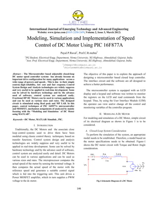
II. MODELING A DC MOTOR
For modeling and simulation of a DC Motor, simple circuit
of its electrical diagram as shown in Figure 1 is to be
considered.
A. Closed-Loop System Consideration
To perform the simulation of the system, an appropriate
model needs to be established. Therefore, a model based on
the motor specifications needs to be obtained. Figure-1
shows the DC motor circuit with Torque and Rotor Angle
consideration.
Fig.1.Schematic Diagram of a DC Motor
2. International Journal of Emerging Technology and Advanced Engineering
Website: www.ijetae.com (ISSN 2250-2459, Volume 2, Issue 3, March 2012)
147
B. System Equation
The motor torque T is related to the armature current, i , by
a torque constant K;
(1)
The generated voltage, ea, is relative to angular velocity by
(2)
(3)
From Fig. 1 we can write the following equations based on
the
Newton’s law com bined with the Kirchoff’s law:
+ b = Ki (4)
+RI =V - K (5)
C. Transfer Function
Using the Laplace transform, equations (3) and (4) can be
written as:
(6)
(7)
Where s denotes the Laplace operator. From (7) we can
express I(s):
(8)
and substitute it in (5) to obtain:
(9)
This equation for the DC motor is shown in the block
diagram in Fig. 2. From equation (8), the transfer function
from the input voltage, V(s), to the output angle θ, directly
follows:
(10)
From the block diagram in Fig. 2, it is easy to see that the
transfer function from the input voltage, V(s), to the
angular velocity is:
(11)
D. MATLAB Representation
To represent the model with m-file, we can perform the
Fig. 2 data as follows;
Power P = 0.37 kW
Speed N = 1500 rpm ,
Rotor Inertia J is assumed to be 0.01
Supply voltage = 220 volts.
Calculate the torque constant K;
(12)
K=1.4
By using equation (3) for
(13)
At the steady state (used as analyzed data), both I and ω are
stabilized;
And
(14)
(15)
Following value are assigned to be used for our desire
DC Motor Model:
Vt = 220v; J=0.01; b=0.02; k=1.4; Ra=13.5 Ω; La=132.5
mH. By calculating and assuming the require data as above.
3. International Journal of Emerging Technology and Advanced Engineering
Website: www.ijetae.com (ISSN 2250-2459, Volume 2, Issue 3, March 2012)
148
Figure.2 Closed loop system that Representing the DC motor
D. Analysis
We plot the step, impulse and frequency responses of the
given motor model:
Fig.3(a) Step response using simulink model.
Fig. 3(b) Impulse response using simulink model.
III . SIMULINK MODEL
The block diagram of Fig. 2 can be represented and
created as a model as shown in Fig. 4. The approaching to
construct this model can easily be done by using Simulink
Library. The M- file and Simulink model can be combined
by the following commands and these are commands used
in M-file which can be solve it.
Figure.4 Model created in SIMULINK Toolbox of MATLAB
Figure.5. Final results using simulink model (with Step response)
4. International Journal of Emerging Technology and Advanced Engineering
Website: www.ijetae.com (ISSN 2250-2459, Volume 2, Issue 3, March 2012)
149
IV. SYSTEM DESCRIPTION
The input from the stable power supply unit (230 V AC)
is converted into 12v AC by means of a step down
transformer, the output of this is used as input to bridge
rectifier circuit. Here in this system bridge rectifier will
generate 5 V DC with the help of regulator 7805. The
output of the 7805 regulator is used as an input to the PIC.
The PIC will generate pulses to drive the DC motor
according to the requirement. As the output voltage of the
PIC is in mV, driver circuits are used to drive the DC motor
An optical encoder is used to measure the speed of the
motor. The output of the encoder is a stream of pulses with
variable frequency according to the speed of the motor. The
optocouplers were used to isolate the high voltage circuits
from the low voltage controlling signals. The rating of the
motor should be chosen according to the rating of the
power circuit.
For this study a dc shunt motor with ratings 1500 rpm,
220 V, 2.3 A, 0.37 kW is used. The entire operation of the
blocks is explained briefly as follows with the diagram as
shown in figure.6 below.
Fig.6.Circuit diagram for DC Motor speed control.
A. Microcontroller PIC16F877A.
Peripheral Interface Controller (PIC) is a term
introduced by Microchip technology. PIC 16F877A is a
family of CMOS 8-bit Flash microcontrollers[3]. Power
consumption is very low. PIC16F877A is a 40/44-pin
device which can operate at up to 20 MHz clock speed.
It has 8K * 14 words flash program memory, 368*8
RAM data memory, 64bytes of EEPROM nonvolatile
data memory, 8-bit timer with pre-scalar, watchdog
timer, Only 35 single-word instructions to learn, external
and internal interrupt sources and large sink and source
capability. The architecture is shown in Fig.3[3]
Fig.7.Architecture of PIC16F877A Microcontroller
B. Driver Circuit
This driver circuit is designed based on the DC motor
current ratings, The current rating of the DC motor is 2.3
Amp So driver circuit is needed. It is the most popular
and cost effective drive circuits for driving MOSFETs. A
bipolar, non-inverting totem-pole driver as shown in Fig 4.
Transistors can be used to supply higher current to the
motor. This circuit handles the current spikes and power
losses making the operating conditions for the PWM
controller more favorable.
Fig.8 Driver Circuit
5. International Journal of Emerging Technology and Advanced Engineering
Website: www.ijetae.com (ISSN 2250-2459, Volume 2, Issue 3, March 2012)
150
V . SIMULATION RESULTS
The proposed control circuit is implemented using software
module like Real PIC Simulator as shown in Fig 9. For the
purpose of coding the software package used is MPLAB.
Fig.9(a) Output pulses of PIC16F877A through MPLAB IDE for
ω=500rpm
Fig.9 (b) Output pulses of PIC16F877A through MPLAB IDE for
ω=1500 rpm
VI. HARDWARE SETUP AND RESULTS
A. Minimum Hardware connections of PIC16F877A
The results shown are for the motor having parameters:
V = 220 V, ω=1500 rpm, P = 0.37 kW, I=2.3 A.
The minimum hardware connections circuit board is as
shown in Fig.10. Two pins are used to provide supply
voltage tochip. The stable power supply of +5 V is used.
If any suddenly jerk is coming our PIC IC will not
damage. Two pins are also used for ground. In chips with
40pins and more, it is common to have multiple pins for
Vcc and GND. This will help reduce the noise (ground
bounce) in high-frequency systems. The PIC 16F has many
options for the clock source. Most often a quartz crystal
oscillator is connected to input pins OSC1 & OSC2. PIC
16F877A microcontroller can have speed of 0 Hz to 20
MHz.
Figure.10 PIC 16F877A Hardware Connection with Power Supply,
Driver circuit and LCD Display
B. Bridge Rectifiers, Regulator and Driver circuit
The bridge rectifiers,Regulator and driver circuit used to
convert 230 V AC to 12 V DC and 5 V DC to give as input
to the PIC 16F877A controller is shown in Fig.11
Fig.11. Bridge rectifiers, Regulators and driver circuit
C. Optical Encoder and Rotating disk
The most popular type of encoder is the optical encoder,
which consists of a rotating disk, a light source, and a photo
detector (light sensor). The disk .which is mounted on the
rotating shaft, has coded patterns of opaque and transparent
sectors.
Bridge ckt Driver
circuit
LCD
PIC
Power
supply
s
Driver ckt
6. International Journal of Emerging Technology and Advanced Engineering
Website: www.ijetae.com (ISSN 2250-2459, Volume 2, Issue 3, March 2012)
151
As the disk rotates, these patterns interrupt the light
emitted onto the photo detector, generating a digital or
pulse signal output. It is shown in fig. 12 .
Figure.12.Optical Encoder and rotating disc (8 Number of Slots)
which is mounted on the rotating shaft
The corresponding output pulse of PIC is as shown in
Fig 13 on CRO and Fig 14 on LCD
Fig.13Practical output pulse of pic16F877A in CRO
Fig.14.Practically Actual & Ref. speed on LCD ω = 750 rpm
VII. CONCLUSION
The DC machine is considered to be basic electric
machines. The aim of this paper is to introduce Technicians
to the modeling of power components and to use computer
simulation as a tool for conducting transient and control
studies. The Microcontroller based adjustable closed-loop
DC motor speed controller system has been developed. .
The results showed that the microcontroller is a reliable
instrument to control the motor. This system is applicable
to different sizes of motors and capable of controlling the
speed of the motors with very high precision.
VIII. REFERENCES
[1] Wai Phyo Aung, “Analysis on Modeling and Simulink of DC Motor
and its Driving System Used for Wheeled Mobile Robot” , PWASET
VOLUME 26 DECEMBER 2007 ISSN 1307-6884.
[2] Gopal K. Dubey, Fundamentals of Electrical Drives, 2nd edition,
Narosa Publishing House, New Delhi-2007.
[3] Muhammad Ali Mazidi, PIC Microcontroller and Embedded systems
using Assembly and C for PIC16, Pearson Education, 2008.
[4]Ajay V. Deshmukh, “Microcontrollers: Theory and applications”, Tata
McGraw-Hill
[5] 7805 and 7812 Voltage Regulator ICs-Data sheets.
[6] “PIC16F877A” Data sheet from Microchip Corporation.
[7] MPLAB IDE Software-Microchip technology.
Optical
encoder
Rotating
disk