Download to read offline
![CLOSED LOOP PERFORMANCE INVESTIGATION OF
CHOPPER FED DC MOTOR USING VARIOUS
CONTROLLER
1
M.Abinaya,2
P.Nedumal Pugazhenthi,3
S.Selvaperumal,4
G.Prabhakar,5
P.Gnana skandaparthiban
1
P.Gscholar,SyedAmmalEngineering College,Ramanathapuram, TN, INDIA
2
Associate Professor,syedammal Engineering college,Ramanathapuram,TN,INDIA
3
Professor, Syedammal Engineering college, Ramanathapuram,TN,INDIA
4
Assistant Professor,Syedammal Engineering college,Ramanathapuram,TN,INDIA
5
Assistant Professor,SyedAmmal Engineering college,Ramanathapuram,TN,INDIA
1
abinaya987@gmail.com,2
neduaupci@gmail.com,3
perumalvnr@gmail.com,4
gprabhakar2488@gmail.com,5
parthiban_est@gmail.com
Abstract
This paper analyse the study of closed loop performance
investigation of chopper fed separately excited dc motor using
PI controllers. Speed of separately excited DC motor can be
varied below and above the rated speed by various techniques.
Conventional controllers are commonly being used to control
the speed of the DC motors in various industrial applications.
It is to be found as a simple, robust and highly effective when
the load disturbance is small. The aim of this project is to
control this Speed of chopper based separately excited DC
motor. The PWM pulses are generated by the chopper to
control the motor speed.
The duty cycle of the PWM pulse are varied by PI
controller to attain the closed loop response. The chopper
firing circuit receives variable PWM pulses from PI
controller, to produces the variable voltage to the armature of
the motor for achieving desired speed response.
Keywords: separately excited DC motor,chopper,proportional
integral controller(PI),proportional integral derivative(PID).
I. Introduction
The development of high performance motor drives is very
important in industrial as well as other purpose applications
such as steel rolling mills, electric trains and robotics.
Generally, a high performance motor drive system must have
good dynamic speed command tracking and load regulating
response to perform task.DC drives are choosen because of
their simplicity,easiness of application, high reliability,
flexibility and less cost, this is the backbone for industrial
applications, and home appliances.wherethe speed and
position control of motor are required. DC drives are less
complex with a single power conversion from AC to DC.
Again the speed torque characteristics of DC motors are much
more superior to That of AC motors. A DC motors provide
excellent control of speed for acceleration and deceleration.
DC motors have a long tradition of use as adjustable speed
machines and a wide range of options have developed for this
purpose. In these applications, the motor should be precisely
controlled to give the desired performance. The controllers of
the speed that are conceived for goal to control the speed of
DC motor to execute one variety of tasks, is of several
conventional and numeric controller types, the controllers can
be: proportional integral (PI), proportional integral derivative
(PID) Fuzzy Logic Controller (FLC) or the combination
between them: Fuzzy-Neural Networks, Fuzzy Genetic
Algorithm, Fuzzy-Ants Colony, Fuzzy-Swarm[7].
The proportional – integral – derivative (PID) controller
operates the majority of the control system in the world. It has
been reported that more than 95% of the controllers in the
industrial process control applications are of PID type as no
other controller match the simplicity, clear functionality,
applicability and ease of use offered by the PID controller [3],
[4].
PID controllers provide robust and reliable performance for
most systems if the PID parameters are tuned properly. The
major problems in applying a conventional control algorithm
(PI, PD, PID) in a speed controller are the effects of non-
linearity in a DC motor. The nonlinear characteristics of a DC
motor such as saturation and fiction could degrade the
performance of conventional controllers [1], [2].
Generally, an accurate nonlinear model of an actual DC motor
is difficult to find and parameter obtained from systems
identification may be only approximated values. The field of
Fuzzy control has been making rapid progress in recent years.
Fuzzy logic control (FLC) is one of the most successful
applications of fuzzy set theory, introduced by L.A Zadeh in
1973 and applied (Mamdani 1974) in an attempt to control
system that are structurally difficult to model. Since then,
FLC has been an extremely active and fruitful research area
with many industrial applications reported [5].
In the last three decades, FLC has evolved as an alternative or
complementary to the conventional control strategies in
various engineering areas. Fuzzy control theory usually
provides non-linear controllers that are capable of performing
different complex non-linear control action, even for uncertain
nonlinear Systems. Unlike conventional control, designing a
FLC does not require precise knowledge of the system model
such as the poles and zeroes of the system transfer functions.
Imitating the way of human learning, the tracking error and
the rate change of the error are two crucial inputs for the
design of such a fuzzy control system [6], [7].
II.Proposed system
Armature voltage control method is used to vary the
speed of separately excited DC motor below and up to the
rated speed. (Fig.1) shows the block diagram of the proposed
method. The system consists of buck converter type DC–DC
power converter or chopper for driving the separately excited
DC motor. The performance of the DC drive will be based on
International Journal of Applied Engineering Research, ISSN 0973-4562 Vol. 10 No.55 (2015)
© Research India Publications; httpwww.ripublication.comijaer.htm
2216](https://image.slidesharecdn.com/closedloopperformanceinvestigation-200209084857/85/Closed-loop-performance-investigation-1-320.jpg)
![CLOSED LOOP PERFORMANCE INVESTIGATION OF
CHOPPER FED DC MOTOR USING VARIOUS
CONTROLLER
1
M.Abinaya,2
P.Nedumal Pugazhenthi,3
S.Selvaperumal,4
G.Prabhakar,5
P.Gnana skandaparthiban
1
P.Gscholar,SyedAmmalEngineering College,Ramanathapuram, TN, INDIA
2
Associate Professor,syedammal Engineering college,Ramanathapuram,TN,INDIA
3
Professor, Syedammal Engineering college, Ramanathapuram,TN,INDIA
4
Assistant Professor,Syedammal Engineering college,Ramanathapuram,TN,INDIA
5
Assistant Professor,SyedAmmal Engineering college,Ramanathapuram,TN,INDIA
1
abinaya987@gmail.com,2
neduaupci@gmail.com,3
perumalvnr@gmail.com,4
gprabhakar2488@gmail.com,5
parthiban_est@gmail.com
Abstract
This paper analyse the study of closed loop performance
investigation of chopper fed separately excited dc motor using
PI controllers. Speed of separately excited DC motor can be
varied below and above the rated speed by various techniques.
Conventional controllers are commonly being used to control
the speed of the DC motors in various industrial applications.
It is to be found as a simple, robust and highly effective when
the load disturbance is small. The aim of this project is to
control this Speed of chopper based separately excited DC
motor. The PWM pulses are generated by the chopper to
control the motor speed.
The duty cycle of the PWM pulse are varied by PI
controller to attain the closed loop response. The chopper
firing circuit receives variable PWM pulses from PI
controller, to produces the variable voltage to the armature of
the motor for achieving desired speed response.
Keywords: separately excited DC motor,chopper,proportional
integral controller(PI),proportional integral derivative(PID).
I. Introduction
The development of high performance motor drives is very
important in industrial as well as other purpose applications
such as steel rolling mills, electric trains and robotics.
Generally, a high performance motor drive system must have
good dynamic speed command tracking and load regulating
response to perform task.DC drives are choosen because of
their simplicity,easiness of application, high reliability,
flexibility and less cost, this is the backbone for industrial
applications, and home appliances.wherethe speed and
position control of motor are required. DC drives are less
complex with a single power conversion from AC to DC.
Again the speed torque characteristics of DC motors are much
more superior to That of AC motors. A DC motors provide
excellent control of speed for acceleration and deceleration.
DC motors have a long tradition of use as adjustable speed
machines and a wide range of options have developed for this
purpose. In these applications, the motor should be precisely
controlled to give the desired performance. The controllers of
the speed that are conceived for goal to control the speed of
DC motor to execute one variety of tasks, is of several
conventional and numeric controller types, the controllers can
be: proportional integral (PI), proportional integral derivative
(PID) Fuzzy Logic Controller (FLC) or the combination
between them: Fuzzy-Neural Networks, Fuzzy Genetic
Algorithm, Fuzzy-Ants Colony, Fuzzy-Swarm[7].
The proportional – integral – derivative (PID) controller
operates the majority of the control system in the world. It has
been reported that more than 95% of the controllers in the
industrial process control applications are of PID type as no
other controller match the simplicity, clear functionality,
applicability and ease of use offered by the PID controller [3],
[4].
PID controllers provide robust and reliable performance for
most systems if the PID parameters are tuned properly. The
major problems in applying a conventional control algorithm
(PI, PD, PID) in a speed controller are the effects of non-
linearity in a DC motor. The nonlinear characteristics of a DC
motor such as saturation and fiction could degrade the
performance of conventional controllers [1], [2].
Generally, an accurate nonlinear model of an actual DC motor
is difficult to find and parameter obtained from systems
identification may be only approximated values. The field of
Fuzzy control has been making rapid progress in recent years.
Fuzzy logic control (FLC) is one of the most successful
applications of fuzzy set theory, introduced by L.A Zadeh in
1973 and applied (Mamdani 1974) in an attempt to control
system that are structurally difficult to model. Since then,
FLC has been an extremely active and fruitful research area
with many industrial applications reported [5].
In the last three decades, FLC has evolved as an alternative or
complementary to the conventional control strategies in
various engineering areas. Fuzzy control theory usually
provides non-linear controllers that are capable of performing
different complex non-linear control action, even for uncertain
nonlinear Systems. Unlike conventional control, designing a
FLC does not require precise knowledge of the system model
such as the poles and zeroes of the system transfer functions.
Imitating the way of human learning, the tracking error and
the rate change of the error are two crucial inputs for the
design of such a fuzzy control system [6], [7].
II.Proposed system
Armature voltage control method is used to vary the
speed of separately excited DC motor below and up to the
rated speed. (Fig.1) shows the block diagram of the proposed
method. The system consists of buck converter type DC–DC
power converter or chopper for driving the separately excited
DC motor. The performance of the DC drive will be based on
International Journal of Applied Engineering Research, ISSN 0973-4562 Vol. 10 No.55 (2015)
© Research India Publications; httpwww.ripublication.comijaer.htm
2216](https://image.slidesharecdn.com/closedloopperformanceinvestigation-200209084857/75/Closed-loop-performance-investigation-1-2048.jpg)
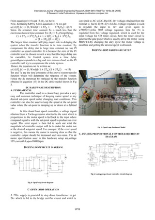
![VI. COMPARATIVE ANALYSIS FOR THEORITICAL AND
PRATICAL VALUES
Table 1: Comparative analysis for theoreticaland practical values
VII.COMPARSION OF OUTPUT VOLTAGE BETWEEN
PRATICAL AND THEORITICAL VALUE
Fig 7: Comparison of output voltage between theoretical
value and practical values
VIII. ANALOG PROPORTIONAL CONTOLLER
HARDWARE
MODEL
Fig 8.Analog Proportional Controllerhardware Model
XI.OUTPUT VOLTAGE FOR RA=3.3KΩ,RB=5KΩ ,C=0.01μF
Fig9: output voltage for resistor ra=3.3kΩ, rb=5kΩ, c=0.01μf
X.ANALOG CONTROLLER OPERATION
In analog PI controller the inversion input voltage
230v is converted into 24v using step down transformer. The
half diode bridge rectifier is used between the transformer and
regulator which is used to convert 24v AC to 24v DC. In PI
controller is consist of 6 operational amplifiers with specified
resistor with potential transformer. The gate pulse is produced
by 555 timer by using the voltage regulator 7805(+5v), and
here the IC is MOSFET chosen. Gate signal is given to
theMOSFET terminal the motor speed is controlled by
varying the potential transformer which is connected to the PI
controller.
XI. CONCLUSION
The speed of a dc motor has been successfully
controlled by using a Chopper as a converter and
Proportional-Integral type Speed and Current controller based
on closedloop system model. Initially a simplified closed loop
model for speed control of DC motor is considered and
requirement of current controller is studied.
The hardware setup is carry out in this project by varying
reference speed and by varying load are also obtained.
REFERENCES
[1] B.J. Chalmers, “Influence of saturation in brushless
permanent magnet drives.” IEE proc. B, Elect.Power Appl,
vol.139, no.1, 1992.
[2] C.T. Johnson and R.D. Lorenz, “Experimental
identification of friction and its compensation in precise,
position controlled mechanism.” IEEE Trans. Ind, Applicant,
vol.28, no.6, 1992.
[3] Zhang, N. Wang and S. Wang, “A developed method of
tuning PID controllers with fuzzy rules for integrating
process,” Proceedings of the American Control Conference,
Boston, 2004, pp. 1109-1114.
[4] K.H. Ang, G. Chong and Y. Li, “PID control system
analysis, design and technology,” IEEE transaction on Control
System Technology, Vol.13, No.4, 2005, pp. 559-576.
0
1
2
3
4
5
6
1 2 3 4 5 6 7 8
Practical
value
Theoritic
al value
Different combination of Ra,Rb,C
International Journal of Applied Engineering Research, ISSN 0973-4562 Vol. 10 No.55 (2015)
© Research India Publications; httpwww.ripublication.comijaer.htm
2219](https://image.slidesharecdn.com/closedloopperformanceinvestigation-200209084857/85/Closed-loop-performance-investigation-4-320.jpg)
![[5] H.X.Li and S.K.Tso, "Quantitative design and analysis of
Fuzzy ProportionalIntegral-Derivative Control- aStep towards
Auto tuning", International journal of system science, Vol.31,
No.5, 2000, pp.545-553.
[6] Thana Pattaradej, GuanrongChen and pitikhateSooraksa,
"Design and. Implementation of Fuzzy PID Control of a
bicycle robot" Integrated computer-aided engineering, Vol.9,
No.4, 2002
[7] Weiming Tang, Guanrong Chen and Rongde Lu, “A
Modified Fuzzy PI Controller for a Flexible-joint Robot Arm
with Uncertainties”, Fuzzy Set and System, 118 (2001) 109-
119
[8] Moleykutty George., Speed Control of Separately Excited
DC motor, American Journal of Applied Sciences, 5(3), 227-
233, 2008.
[9] SIMULINK, Model-based and system-based design using
Simulink, Mathsworks, Inc, Natick, MA, 2000.
[10] MATLAB SIMULINK, version 2009, SimPowerSystem,
One quadrant chopper DC drive.
[11] C.U. Ogbuka, Performance characteristics of Controlled
separately excited dc motor, Pacific Journal of Science and
Technology, 10(1), 67-74.
International Journal of Applied Engineering Research, ISSN 0973-4562 Vol. 10 No.55 (2015)
© Research India Publications; httpwww.ripublication.comijaer.htm
2220](https://image.slidesharecdn.com/closedloopperformanceinvestigation-200209084857/85/Closed-loop-performance-investigation-5-320.jpg)

This document analyzes the closed-loop speed control of a chopper-fed separately excited DC motor using PI controllers. It presents the modeling of a separately excited DC motor and discusses various controller types for DC motor speed control. The proposed system uses a buck converter/chopper to control the armature voltage and thereby the speed of the DC motor. PI controllers are used to generate PWM pulses for the chopper by comparing the reference and feedback speeds. Simulation and experimental results are presented to validate the closed-loop speed control using PI controllers for different load conditions.