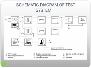
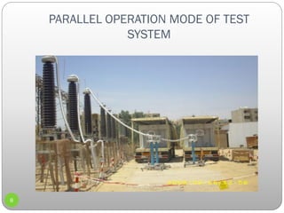
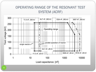
This document discusses voltage testing and partial discharge measurement techniques for power cable accessories. It provides:
1) An overview of the objective to compare cable testing best practices and determine cable defects using partial discharge methods.
2) A description of an ACRF test system used, including its components like an HV reactor, control unit, and voltage divider.
3) Details on partial discharge measurement methods like using high frequency current transformers and coupling capacitors to detect discharges in cables.
4) The conclusion that resonant testing between 20-300Hz along with partial discharge detection reduces risks from cable systems after installation by locating faults.
Principles of Cable Sizing; current carrying capacity, voltage drop, short circuit.
Cables are often the last component considered during system design even if in many situations cables are the true system’s lifeline: if a cable fails, the entire system may stop. Cable reliability is therefore extremely important, then a cable system should be engineered to last the life of the system in the installation environment for the required application. Environments in which cable systems are being used are often challenging, as extreme temperatures, chemicals, abrasion, and extensive flexing. These variables have a direct impact on the materials used for cable insulation and jacketing as well as the construction of the cable. Using a systematic approach will help ensure that designer select the best cable for the required application in the installation environment. This lessons will provide students main guidelines for perform this approach.
Practical handbook-for-relay-protection-engineersSARAVANAN A
The ‘Hand Book’ covers the Code of Practice in Protection Circuitry including standard lead and device numbers, mode of connections at terminal strips, colour codes in multicore cables, Dos and Donts in execution. Also, principles of various protective relays and schemes including special protection schemes like differential,
restricted, directional and distance relays are explained with sketches. The norms of protection of generators, transformers, lines & Capacitor Banks are also given.
Transformer vector group_test_conditionsSARAVANAN A
Test Conditions for various vector groups commonly under use are listed along with pictorial representation. Assuming the reader has sufficient exposure to transformer winding connections.
Transformer Vector Group Test conditions
YNd1, YNd11, Dyn11, YNyn0and more
In-Country Training
On
Operation, Maintenance, Protection & Control of 33/11 kV Substation
Project Name: Design, Supply, Installation, Testing & Commissioning of 33/11 kV sub-stations with source end feeder bays.
Contract No: BREB/UREDS/W-01A-001/02/2016-2017
BREB/UREDS/W-01A-002/03/2016-2017
BREB/UREDS/W-01A-004/04/2016-2017
Testing and Condition Monitoring of Substation EquipmentsSumeet Ratnawat
Testing and condition monitoring of substation equipments,Transformer specifications,Monitoring of Transformer,On-load Tap changer,Overhauling,Tan delta and capacitance,Thermal imaging,Sweep frequency response analysis,Oil analysis of Switchgear elements containing oil,tests on insulating oil,Breaker monitoring,Condition monitoring of CT,Condition monitoring of CVT,Surge Arresters,Condition monitoring of relays.
This is the simple ppt explaining about the main components of the power systems. especially we are determining the insulators and its types with real time pictures which are attractive,
Tan delta is the insulation power factor & is equal to the ratio of power dissipated in the insulation in watts to the product of effective voltage & current in volt ampere when tested under sinusoidal voltage.
About Transmission Line.
Transmission Lines
Classification Of Transmission Lines
Overhead Power Line
Advantages Of Overhead Transmission Lines
Disadvantages Of Overhead Transmission Lines
Nominal “T” Method
Nominal “Pi” Model of a Medium Transmission Line
Underground Transmission Lines
Classification Of Underground Cables
Advantages Of Underground Cables
Disadvantages Of Underground Cables
A presentation explaining how to calculate fault currents for 3-phase or 1-phase faults in power grid. Particularly useful for engineers working in electrical power transmission company.
Seminar for eight semester electrical engineering on Conventional and
Un-Conventional Partial Discharge Detection Methods in High Voltage XLPE Cable Accessories
This paper proposes fault location model for underground power cable using microcontroller. The aim of this project is to determine the di stance of underground cable fault from base station in kilometers. This project uses the simple c oncept of ohm�s law.When any fault like short circuit occurs,voltage drop will vary depending on the length of fault in cable,since the current varies. A set of resistors are ther efore used to represen t the cable and a dc vol tage is fed at one end and the fault is detected by detecting the change in voltage using a analog to voltage converter and a microcontroller is used to make the necessary calculations so that the fault distance is displayed on the LCD display.
EXPERIMENTAL DETERMINATION AND ANALYSIS OF TRANSMISSION LINE PERFORMANCEijiert bestjournal
It is necessary to calculate the voltage,current a nd power at any point on a transmission line provided the values at one point are known. We are aware that in three phase circuit problems it is sufficient to compute results in one phase and subsequently predict results in the other two phases by exploiting the three phase symm etry. Although the lines are not spaced equilaterally and not transposed,the resulting asy mmetry is slight and the phases are considered to be balanced. As such the transmission line calcu lations are also carried out on per phase basis. For that purpose in the transmission line demo pane l we will be designed to �To study the performance of the line.1)e.g. Relation between sen ding end quantity and receiving end quantity,Ferranti effect,efficiency of power line etc.2) To demonstrate fault clearing process using distance relay(Future Scope)
A 60 GHz CMOS Power Amplifier for Wireless CommunicationsIJECEIAES
This paper presents a 60 GHz power amplifier (PA) suitable for wireless communications. The two-stage wideband PA is fabricated in 55 nm CMOS. Measurement results show that the PA obtains a peak gain of 16 dB over a -3 dB bandwidth from 57 GHz to 67 GHz. It archives an output 1 dB compression point (OP1dB) of 4 dBm and a peak power added efficiency (PAE) of 12.6%. The PA consumes a total DC power of 38.3 mW from a 1.2 V supply voltage while its core occupies a chip area of 0.45 mm 2 .
Cyclic voltammetry readout circuitry for DNA biosensor applicationjournalBEEI
Cyclic voltammetry electrochemical biosensors reported a wide usage and applications for its fast response, able to be miniaturized and its sensitivity. However, the bulky, expensive and laboratory-based readout circuitry made it impossible to be used in the field-based environment. A miniaturized and portable readout circuitry for the DNA detection using hybridization technique had been design and developed in this work. It embedded with fabricated FR4 based sensor and produced respective current when the applied voltage was within the range of 0 to 0.5 V. The readout circuitry had been verified with five analysis environments. Bare Au with distilled water (dH2O), bare Au with ferricyanide reagent solution, DNA immobilization, DNA non-hybridization and DNA hybridization. All the results performed produced peak cathodic current when the applied input voltage is within 0.5 V to 3 V and hence proved that the miniaturized and portable readout circuitry is suitable to be implemented for cyclic voltammetry electrochemical biosensor.
For Environment Protection against harmful emisison and aquatic life, It is necessary to implement the standard in order to control the Chemcial Oxygen demand, Biological oxygen demand, Total suspended solid, Total dissolved solid, Oil & Greece Etc.
Electrical and Energy Audit performs in order to apply safety procedure to electrical distribution network along with energy saving protocol in order to reduce the carbon foot print. Energy efficiency solution is required to control the consumption of electricity thus reduce the dependence on fossil fuel usage and economy import policy f fossil fuel.
Probability Estimation for the Fault Detection and Isolation of PMU-Based Tra...Syed Atif Naseem
For fault detection in the transmission line and isolate the faulty transmission line with in the limited period, phasor measurement unit is installed at the buses of smart grid in order to communicate with other PMU’s (Phasor Measurement Unit). For its reliability analysis, formal verification is necessary in order to investigate its accuracy, stability and efficiency when fault is occurred on the network. Through probabilistic analysis of PMU based transmission network via PRISM model checker tool, we can estimate the failure probability of network and take a corrective action and maintenance so that, faulty component can be replaced in advance to avoid the complete failure of system
1. EE-471 HIGH VOLTAGE ENGINEERING
Voltage Testing & Partial Discharge
Measurement For Power Cable Accessories
PRESENTED BY : SYED ATIF CHISHTI
SUBMITEDTO : PROF DOC :BULENT BILIR
1
2. PRESENTATION SEQUENCE
2
OBECTIVE
INTRODUCTION
ACTESTAFTER INSTALLATION
ACRF TEST SYSTEM
SCHEMATIC DIAGRAM OFTEST SYSTEM
PARALLEL OPERATION MODE OFTEST SYSTEM
PARTIAL DISCHARGE METHODS & PRINCIPLE.
DISCUSSION & CONCLUSION.
OBJECTIVE :
To compare best practices for cable testing.
Predictive diagnostic programs to aging cable.
To determine the faulty joints cable defects
3. INTRODUCTION
Using Frequency tuned resonance
Test system (20-300 Hz) to calculate
PD measurement.
PD measurement method are
necessary to trace defect and
insulation of cable.
Voltage testing provide information
about defect in the insulation is
dangerous or not for later operation.
Calibration is done through PD
calibrator on the cable termination.
3
Power Cables importance in
Transmission & Distribution
system
Consist of :
Cable
Joint
Termination
Identification & Localization of
partial discharge.
4. AC TEST AFTER INSTALLATION
4
Follow the international standards IEC 60840 and IEC
62067 for testing of Power cable insulation and their
accessories.
Apply : sinusoidal waveform, frequency: 20 and 300 Hz,
voltage applied for 1.7 U0 /1 hour
5. Methods of Voltage Generated
5
By a reactor with variable inductance and fixed excitation
frequency 50 or 60 Hz (ACRL) test system.
By a reactor with fixed inductance and frequency tuned
voltage excitation (ACRF) test systems.
6. ACRF TEST SYSTEM
6
HV Reactor
ExciterTransformer
Control Unit
Feeding Unit
Blocking Impedance
Voltage Divider & Software
Frequency Convertor + Protection Impedance.
10. PARTIAL DISCHARGE
Partial discharges are a sensitive measure of local electrical
stress and the measurement is often used as a quality check of
the insulation.
Cable has small voids, cavities, insulating contaminant
conductive protrusions in different interfaces or mechanical cuts.
Erosion by ion bombardment and chemical effects gradually
change small defects to electrical trees with consequent final
breakdown.
10
11. METHODS OF PD MEASUREMENTS
11
HIGH FREQUENCY CURRENTTRANSFORMER
HFCT method at cross bonding box for 220 kV or earth wire of 66 kV for XLPE cable
systems Showed high sensitivity and calibration is possible using PD calibrator on the
cable terminations.
COUPLING CAPACITOR
PD detection of high frequency signal generated from PD activities. Measurement by use of
a coupling capacitor is physically limited to a maximum detectable cable length of
approximately 2 km, depending on cable parameters and PD background noise.
12. WORKING PRINCIPLE
12
The sensitivity of the partial discharge detector has to be modified until the
detector shows the calibration charge.
For 220 kV, PD measurements carried out during HV tests, using a test
sequence providing several increase the voltage in steps of 127 Kv (U0) and take
a PD-measurement recording during 1 minute and afterwards increase the voltage in
further steps until 216 kV
At each step note the measured PD value.
Once reaching 216 kV leave this voltage applied for 1 hour and observes if
there is a change in the recorded PD pattern and value.
While ramp the test voltage down, take another PD measurement for 1 minute
at 127 kV.
14. PARTIAL DISCHARGE
MEASUREMENT
14
Internal sensors integrated in each accessory or external
sensors HFCT placed inside bonding link boxes.
The PD sensitivity using HFCT the central measuring
frequency is recommended is to lie between 2 MHz and 10
MHz in a flat zone of the frequency spectrum.
16. 16
Test carried out on two cables having specification
1x3x1600 mm2,CU /XLPE/LEAD/HDPE ,220 kV with approximately 13 km long,19
joints/phase, 3 straight joint box and 16 insulated joint box which are divided into two
sections by means of joints and it is terminated by composite three outdoor and three
GIS sealing ends per circuit.
The result was a resonant frequency of 35.53 Hz for test voltage 216 kV.
Inject a calibration pulse with known quantity of charge at the outdoor system
termination (i.e., between HV and ground terminals), the sensitivity of the PD detector
has to be modified until the detector shows the calibration charge.
PD pulses occur in very short time, the width and rise time of the pulses are in the
nanosecond region. Consequently, PD pulses with energy frequency up to hundred
MHZ are generated these PD pulses will travel through the cable earth conductor and
finally can be recorded by the sensors
TEST RESULT & DISCUSSION
18. variation OF PC pattern during
PD measurement
PD measurement OF pattern
with some noise
18
19. 19
EXAMPLE OF JOINT FAILURE DURING
WITH STAND TEST BY USING RESONANT TEST
SYSTEM
20. CONCLUSION
20
After installation of cable , test for HV/EHV XLPE cables system
by using resonant test system of (20 Hz -300 Hz) combined with
PD detection is performed by using HFCT sensors at each cross
bonding (CB) link boxes reduces the risk from the service.
After detecting the location of fault and repair the cables and
their accessories was done exactly in the same place given good
results.
The experiences also show that the test voltage with U0 for 24 h
is not feasible for incidence of failure after the test could be
occurred.