Downloaded 111 times


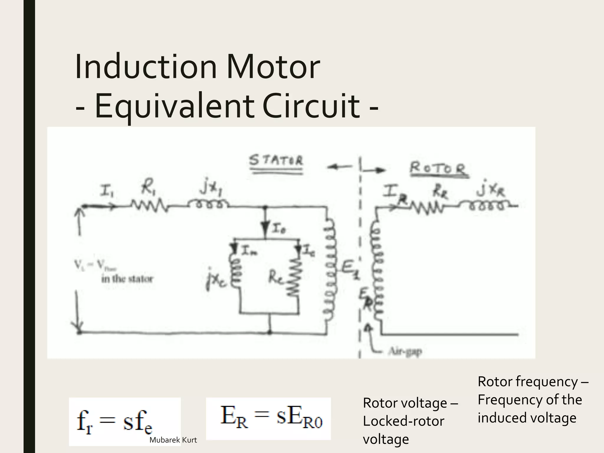


The document discusses induction motors, including their structure, basic concepts, equivalent circuit, power and torque characteristics, and speed control. It provides examples of calculations related to synchronous speed, slip, rotor speed, power, torque, and other induction motor parameters. It also describes methods for testing induction motors to determine their equivalent circuit components.