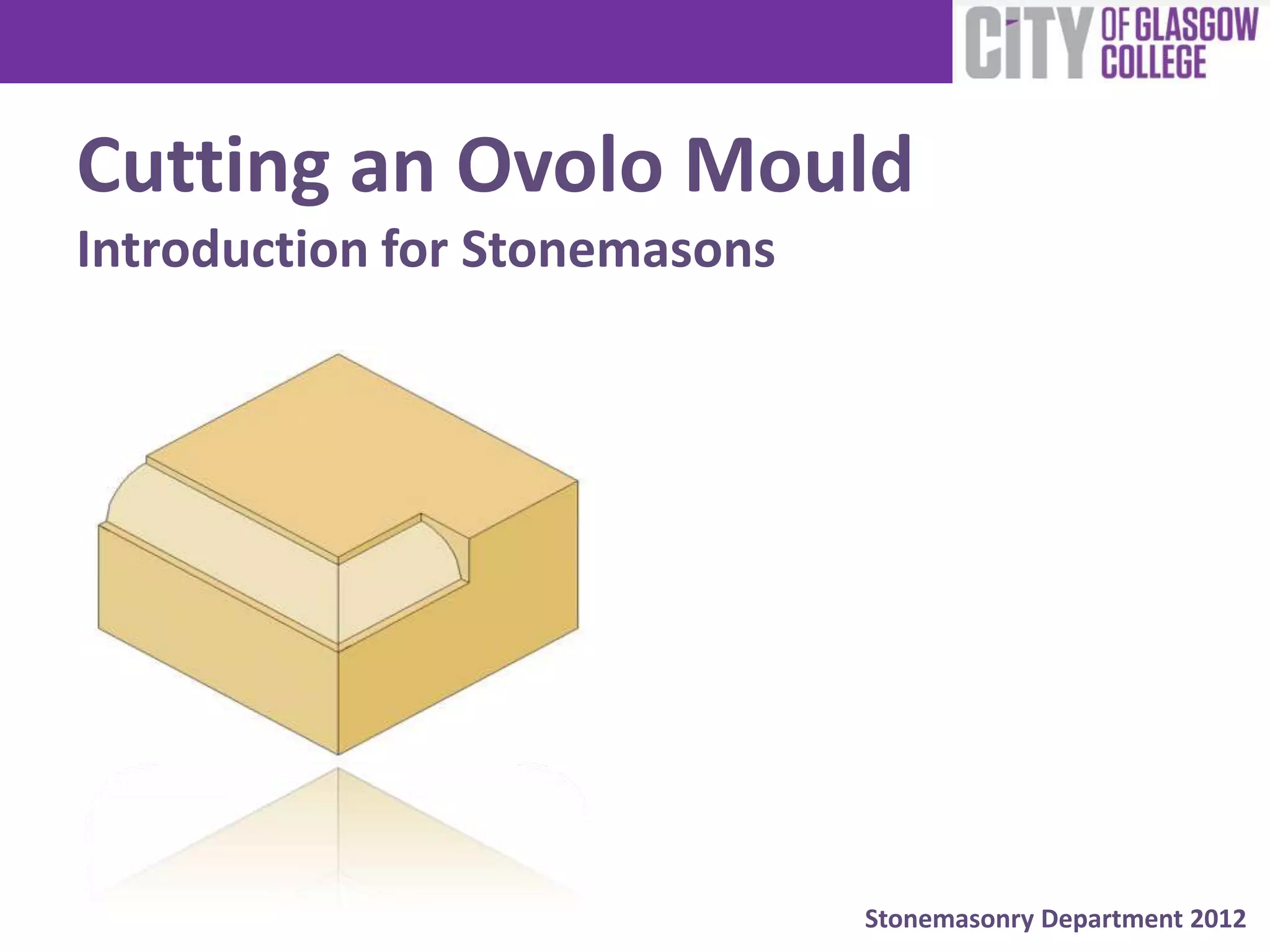
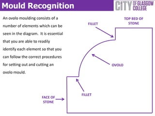
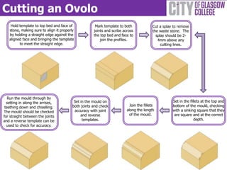
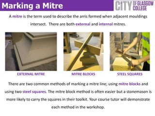
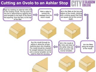
The document provides instructions for drawing two types of scotia curves used in stonemasonry: quadrants and elliptical. For quadrants, the steps include laying out a grid, finding center points, scribing curves, and adding fillets. For elliptical curves, the steps involve laying out radiating lines from a center point using equal step offsets to find curve points and draw the curve.
The document provides step-by-step instructions for constructing a hexafoil shape using geometric principles. It describes drawing concentric circles divided into six sections and then drawing additional concentric circles centered on the divisions to form the intricate hexafoil pattern. Thirteen steps are outlined to first lay guidelines and construction lines, then draw the nested circles and terminating curves to produce the finished hexafoil shape.
The document provides instructions for drawing a trefoil shape in 8 steps. It first involves drawing a circle and equilateral triangle inside the circle. Then concentric circles are drawn from the points of the triangle and the center point. Intersecting arcs are drawn from the center point to the triangle points to complete the trefoil shape. The steps provide details on setting compass radii and drawing various circles and arcs to accurately construct the trefoil design.
This document discusses oblique drawings and related concepts. It defines oblique lines as lines parallel to any oblique axis. It explains that objects not parallel to an oblique axis are non-oblique lines. Angles on object surfaces parallel to the front projection plane or receding plane are considered oblique angles. Circles parallel to the front projection plane appear at actual size, while on a receding plane they appear as ellipses. Arcs parallel to the projection plane show their true size. The document provides examples of constructing oblique drawings using the box method and exercises readers to redraw objects in cavalier and cabinet oblique drawings.
This document provides an overview of surveying and leveling. It defines surveying as determining the relative positions of points on Earth through direct or indirect measurements. The main objectives of surveying are preparing maps and plans. Leveling is defined as determining relative heights or elevations of points through direct measurement of vertical distances from a reference level. Common instruments used for leveling include a level, tripod, staff, tape, and pegs. Leveling follows the principle of obtaining a horizontal line of sight to measure vertical distances of points above or below this line. Key leveling terms defined include bench mark, height of instrument, backsight, foresight, and change point. Methods for recording level data in a field book are also
This lecture contains the detail of isometric projections of an object. This will improve your skills to draw isometric views which is the major part of engineering drawings.
Intersection OF SOLIDES
THIS SLIDE CONTAINS WHOLE SYLLABUS OF ENGINEERING DRAWING/GRAPHICS. IT IS THE MOST SIMPLE AND INTERACTIVE WAY TO LEARN ENGINEERING DRAWING.SYLLABUS IS RELATED TO rajiv gandhi proudyogiki vishwavidyalaya / rajiv gandhi TECHNICAL UNIVERSITY ,BHOPAL.
This document provides a summary of key geometric elements and methods for geometric construction, including:
- Points, lines, angles, and their properties
- Methods for constructing triangles, circles, ellipses, parabolas, and determining foci of conic sections
- Techniques like parallelism, perpendicularity, bisection, and transferring geometric shapes and figures
The document covers essential geometric concepts and various construction techniques in technical drawing.
This document provides an overview of linear measurements and chain surveying techniques. It discusses different types of ranging methods, including direct and reciprocal ranging, to locate intermediate points along a survey line. It also describes instruments used for chain surveying, such as different types of chains, tapes, arrows, ranging rods, and plumb bobs. The key principle of chain surveying is that it involves measuring the sides of triangles within the survey area using a chain or tape, without taking any angular measurements.
This document discusses construction surveying techniques for setting out buildings, roads, pipelines and other structures based on site plans. It describes establishing horizontal and vertical control points, then setting secondary and detail points to mark locations of features. Batter boards are used to temporarily reference building corners by stretching string lines between boards. For pipelines, offset stakes and batter boards give line and grade, with the string line run directly over the pipe centerline. An example problem outlines field steps to lay out a sewer from a house to an existing manhole based on given flow line elevations and minimum slope requirements.
Levelling, also known as heighting, is the process of determining relative height differences between points on the Earth's surface. If the height of one point is known relative to a datum, then the heights of other points can be found relative to the same datum. This is done using a leveling instrument, leveling staff, and following standard procedures such as taking backsight and foresight readings. Care must be taken to eliminate errors from things like atmospheric refraction. Results are typically recorded in a level book or form and can be reduced using methods like height of instrument or rise and fall.
The document discusses structural steel construction, including the various methods used such as beam and column construction, long span construction, and wall bearing construction. It describes the common structural steel members like columns, beams, joists, and trusses that are erected and secured together using fastening systems like bolts and welds to form the structural framework. Details provided on erection plans guide the fabrication and installation of the different steel components.
An isometric drawing is a type of pictorial drawing that makes a three-dimensional object easier to visualize. It is constructed using a 30x60 degree triangle with the height, width, and depth all on a single plane. To make an isometric drawing, construction lines are first drawn at 120 degrees, then the width, height, and depth are measured along these axes before drawing parallel lines and adding detail. Circles and arcs can also be approximated using this method by first drawing a square based on the diameter and connecting points.
Isometric projections for engineering studentsAkshay Darji
The document discusses isometric projections and isometric drawing. It begins by explaining the limitations of orthographic views and how isometric projections show all three dimensions of an object in a single view. It then defines the principles and types of projection, including orthographic, pictorial, axonometric, isometric, dimetric and trimetric. The remainder of the document focuses specifically on isometric projection, defining isometric axes, lines, planes and drawings. It provides examples of how to construct isometric views of various objects from their orthographic projections.
The document discusses different types of traverses and methods for conducting traverse surveys. It describes two types of traverses: open traverses that begin and end at points of known and unknown positions, and closed traverses that begin and end at points of known positions, including closed-loop traverses that begin and end at the same point. It also outlines four methods for determining directions during traversing: chain angle method, free needle method, fast needle method, and measuring angles between lines. Finally, it discusses instruments used for measuring angles like compasses and theodolites, and defines different types of bearings including true, magnetic, and arbitrary bearings.
For those students who start there career in technical line like ITI, Diploma, Engineering of any field this ppt is helpful for them to understand the Engineering Drawing and Its Basic concepts of Orthographics Projection with very good images.
Orthographic projections are a collection of 2D drawings that together accurately represent an object. The six principal views or orthographic views are the front, top, side, and three quarter views. Guidelines for choosing views include selecting the most descriptive front view and using the longest dimension as width or depth. Orthographic projections place an object within an imaginary glass box and freeze views from each side, which are then unfolded. Dimensioning and tolerancing provide manufacturing specifications. Various line types, such as visible, hidden, and center lines, have precedence and are used to fully convey a drawing's geometry and features.
Theodolite surveying part 1 (I scheme MSBTE)Naufil Sayyad
The document provides information about theodolite surveying. It defines a theodolite as an instrument used to measure horizontal and vertical angles accurately. The main types of theodolites are described based on the type of telescope and reading unit. The key components of a transit theodolite are identified and explained. Methods for measuring horizontal angles using a transit theodolite via the direct and repetition methods are outlined, including how to set up the instrument, take readings, and calculate angles.
Plane table surveying is a graphical surveying method where field work and plotting are done simultaneously without the use of a field book. The key accessories of a plane table setup include the plane table, alidade, spirit level, trough compass, and U-fork with plumb bob. There are three main methods used - radiation, intersection, and traversing. Some benefits are that it is a rapid method, errors can be easily detected, and irregular objects can be accurately represented. However, it is not suitable for highly accurate work or in inclement weather conditions.
This document discusses plain scales used in engineering graphics. Plain scales allow measurement of distances and consist of a line divided into equal units. There are two types of plain scales - those that reduce dimensions for smaller drawings and those that enlarge dimensions for drawings of tiny objects. Formulas are provided to calculate the scale ratio and length of a plain scale based on the maximum distance to be measured. Several example problems are included showing how to construct plain scales to specified scale ratios and measurement needs.
The document discusses the development of surfaces, which is the process of laying out the entire surface of a 3D object onto a 2D plane. It describes various methods for developing different types of surfaces and solids, including parallel line development for prisms and cylinders, radial line development for cones and pyramids, and triangulation for more complex shapes. It then provides examples of developing specific objects like prisms, cylinders, pyramids, and cones.
This document discusses the key differences between model drawings and building drawings used in civil engineering. Building drawings must be done at a larger scale since objects are much bigger in real life. The scale used determines the reduction factor to relate actual sizes to drawing sizes. Common views shown in building drawings are plans, elevations, and sections. Plans show the layout and dimensions of elements from a top view. Elevations show the external appearance without dimensions. Sections provide cut views with full dimensions and details. Dimensioning and views are important for structural design. Examples of features shown include walls, windows, doors, floors, and roofs. Architectural design considerations include plot size, bye laws, covered area, and available funds.
This document provides information about masonry chisels. It describes the parts of a chisel including the head, shoulders, and shaft. Chisels are typically made of high carbon tool steel with a tungsten carbide tip. Different types of chisel heads and uses are outlined, including standard, bullnose, fishtail, and lettering chisels. Granite and marble chisels are designed to be more durable due to the hardness of those materials. Chisels can be sharpened manually or mechanically using grinding wheels or diamond sharpening blocks.
The document provides exhibits and descriptions of machinery used in hydrometallurgy and pyrometallurgy plants, including filter presses, jaw crushers, ball mills, valves, flow control devices, pumps, compressors, electro winning cells, lead anatomy anodes, and conveyor belts. Specifically, it showcases 14 exhibits of filter presses, 14 exhibits of jaw crushers and ball mills, 11 exhibits of valves, 7 exhibits of flow control devices, 3 exhibits of lead products, 8 exhibits of pumps and compressors, 2 exhibits of electro winning cells, 2 exhibits of lead anatomy anodes, and 2 exhibits of conveyor belts.
This thesis aims to expand an existing pneumatic breaker model created in Dymola to include additional interacting systems using Hopsan NG simulation software. The author builds Hopsan models of the breaker with both fixed and floating hitting points. Validation is done by comparing model results to measurements from the real breaker and Dymola simulations. The Hopsan models are able to analyze factors like feed force on the operator and vibrations transmitted, improving understanding of the breaker's internal processes.
The document summarizes Soosan's SQ Line Silenced Series of hydraulic breakers. It describes the breakers' advanced percussion mechanism that generates extra power, integrated power control system with different operating modes, and auto shut-off function to prevent damage from blank hammering. It provides details on the breakers' enhanced vibration dampening, robust structure, maintenance friendliness, and ranges from medium to heavy-duty sizes suitable for excavators from 15-100 tons.
This document provides steps to construct an ogee curve using parallel lines and perpendicular bisectors. First, two parallel lines are drawn. Then perpendicular bisectors are drawn to bisect the lines. The intersection of the perpendicular bisectors is the center of the required tangent arcs that form the ogee curve.
Modern glass materials,properties and uses 3FATHIMA VP
This document discusses different types of modern glass materials and their properties and uses. Toughened glass has high mechanical strength and increased resistance to temperature changes, making it suitable for outside windows. Laminated glass has good safety performance, sound insulation, UV prevention, earthquake resistance, and water pressure resistance, making it suitable for areas with human impact and skylights. Patterned glass has decorative effects with strong 3D sense that won't fade and can be reprocessed, making it suitable for room dividers, offices, shelving, and balustrades. Annealed glass has less strength than toughened glass and is used in glass doors and outside windows. Extra clear glass has high visual permeability and is used for interior
The document discusses specifications and estimations for various types of glass. It provides details on the composition, properties, and applications of glass types including annealed glass, heat-strengthened glass, tempered glass, laminated glass, insulating glass, reflective glass, tinted glass, wired glass, patterned glass, and glass bricks. It also discusses factors to consider for determining the safe thickness of glass, safety issues related to glass structures, and companies involved in glass manufacturing.
Fiberglass, or glass-reinforced plastic, is a material made of extremely fine glass fibers set in or surrounded by plastic. It is made by melting glass into fine fibers, which are then bonded together with a plastic resin to form a strong, lightweight material. Fiberglass is used widely in many applications due to its high strength-to-weight ratio, resistance to corrosion, and ability to be molded into complex shapes. Some common uses include building insulation, boats, cars, and building panels.
This document provides information on various sound insulation materials, including their characteristics, pricing, sizes, and intended uses. Glass mineral wool is made from recycled glass, limestone and soda ash to form fine strands that are bound together. It has good tear strength and is lightweight with low environmental impact. Rock mineral wool is made from volcanic rock and recycled slag, and has high compressive strength. It can be used for thermal insulation and fire protection. Foamed plastics like extruded polystyrene are made through an extrusion process and have high compressive strength, water resistance and freeze-thaw performance. Products like Quiet Batt and Studio Pro are high-performance sound absorbing insulation materials used residentially and commercially.
The document discusses different types of partition walls used to divide interior spaces in buildings. It describes timber stud, metal stud, drywall, glass block, and block partitions. Timber stud partitions can be plaster skimmed, dry-lined, or partially glazed. Metal stud partitions are lightweight but strong, consisting of a metal framework covered in plasterboard or fire-resistant sheeting. Glass block partitions are made of translucent glass blocks laid in mortar, sometimes with reinforcement. Block partitions are constructed from masonry blocks.
The document discusses various fiber reinforced plastic (FRP) composite manufacturing processes. It defines FRP composites and describes common matrix materials like thermoset and thermoplastic resins. Manufacturing methods covered include hand lay-up, spray-up, resin transfer molding (RTM), filament winding, pultrusion, matched-die molding, and reaction injection molding (RIM). Each process is explained along with associated materials, equipment, advantages, disadvantages and applications.
Partition walls are used to divide interior spaces. They can be load-bearing or non-load bearing. Common types include timber, brick, clay block, concrete, glass, and metal partitions. Timber partitions use a wooden framework, while brick partitions come in plain, reinforced, and nogging styles. Clay block and concrete partitions use hollow blocks or precast panels. Glass partitions employ sheets or hollow blocks for visibility and soundproofing. Metal partitions make use of metal lath and plaster or steel framing. Proper installation of the chosen partition wall type is important for strength and function.
The document provides information about different types of arches including bell arches, ogee arches, pointed multifoil arches, shoulder arches, jack arches, segmental arches, and drop arches. For each arch, it describes the key characteristics, historical background and origins, examples of use in historical buildings, and basic steps for constructing the arch geometrically. Diagrams are included to illustrate the construction process for some of the arch types. The document serves as an educational reference on classical arch forms.
This document provides information on fiberglass production including:
1) There are four main methods for producing fiberglass: hand lay-up, spray lay-up, pultrusion, and chopped strand mat.
2) Fiberglass was accidentally discovered in the 1930s and was used as a replacement for plywood in aircraft during World War II.
3) The document focuses on Mahavir Enterprise, a manufacturer of fiberglass sheets in India, and describes their production process, applications, and health and safety considerations.
FRP is a composite material made of a polymer matrix reinforced with fibers or particles. The reinforcing materials improve the strength and elasticity of the polymer. Fiber reinforced plastics specifically use fiber reinforcement. Common fiber types include glass, carbon, and aramid fibers. The properties of the FRP depend on the properties of the fibers and matrix, their relative volumes, fiber length and orientation. FRPs are used in applications requiring high strength, stiffness, stability and resistance to heat, chemicals and abrasion.
The document describes various engineering curves including conic sections, spirals, and cycloids. It provides methods for constructing ellipses, parabolas, and hyperbolas using techniques like concentric circles, rectangles, arcs of circles, and directrix-focus definitions. It also demonstrates drawing tangents and normals to these curves. Additional curves covered include involutes, cycloids, trochoids, spirals, and helices.
Flooring refers to any material applied over a floor structure to provide a walking surface. Common flooring materials include carpet, resilient flooring (e.g. vinyl, linoleum), wood, ceramic tile, stone, terrazzo, and seamless chemical coatings. The choice of flooring material depends on factors like cost, durability, noise insulation, comfort, and maintenance requirements. A subfloor provides structural support for the flooring material and may be finished without additional covering. Common flooring types discussed include carpet, wood, resilient, ceramic tile, marble, brick, glass, rubber, and stone flooring.
This document provides information on block walling, including its advantages, standard dimensions, weights, terminology, classifications, bonding arrangements, structural stability, damp proof courses, expansion joints, compressive strength, tolerances, uniform beds and joints, and brick identification, dimensions, classifications, building to gauge, racking back, return corners, toothing, bonds, and construction steps. Block walling is a versatile, durable, and cost-effective building method that provides fire resistance, sound insulation, and inherent thermal mass.
This document provides an introduction to risk assessment for stonemasons. It explains that a risk is the likelihood of harm from a hazard together with the severity of the harm. Common hazards in stonemasonry like angle grinders and ladders are identified. It outlines the five steps to conducting a risk assessment: identifying hazards, identifying those affected, evaluating risks and controls, recording the assessment, and reviewing it. Workers are asked to identify hazards in an image and discuss hazards from their own experience. The document instructs trainees to complete a risk assessment for cutting stone.
This document provides an introduction to electrical safety for stonemasons. It discusses various methods for supplying power on construction sites, including battery tools, generators, and mains power through transformers. It emphasizes the importance of using the proper cables and ensuring equipment is rated for the correct voltage. Safety devices like residual current devices (RCDs) and junction boxes are also outlined. The document provides guidance on inspecting equipment and outlines common electrical injuries and safety tips for working with electricity.
RIDDOR are UK regulations that require work-related injuries, diseases, and dangerous occurrences be reported. The regulations aim to generate reports for authorities to examine incidents and trends and develop prevention strategies. Reportable incidents include deaths, injuries requiring over 7 days off work, dangerous occurrences, and certain work-related diseases diagnosed by a doctor. The responsible person such as an employer must make reports. An accident book must be kept to record any incidents at a construction site.
This document provides instructions for stonemasons on cutting checks and splays in stone. It outlines the steps to mark and cut a check, which involves scribing lines, setting joints with a chisel, cutting a V shape, pitching along the face, setting marginal drafts, and chiseling out the rest of the check. It also details how to cut a splay, including marking splay lines on the joints and face, making the lines safe with a chisel, pitching the joints, setting in joints with marginal drafts, roughing out the center section, chiseling it flat, and polishing for a fine finish if the splay will be visible.
This document provides information for students starting a two-year stonemasonry apprenticeship program. It outlines that students will learn skills in both the classroom and workshop to develop their abilities as stonemasons. Safety equipment requirements are listed for both the workshop and classroom. The document also introduces the teaching staff and provides the course timetable and calendar.
Joint and reverse templates are used to mark straight joints and check return moulds, respectively. Face templates mark faces without mouldings, such as on arch stones, while bed templates mark mouldings on top and bottom beds of stones like columns. Cover templates indicate moulds that do not run the full length of the stone. Wrap around templates are for curved surfaces. Raking/stretch templates are used for moulds applied to sloped joints which stretch the template from the original.
Squares, steel rules, scribers, steel dividers, and beam compasses are essential measuring and marking tools for creating templates. Squares ensure perpendicular lines while steel rules offer accuracy. Scribers score sheet metal and dividers mark curves. Beam compasses reach larger radii. Snips remove waste but files accurately reduce templates to working lines using various shapes and sizes of files. Steel wool and permanent markers provide finishing touches by cleaning and clearly marking templates.
The document provides instructions for constructing a regular pentagon using basic geometric techniques:
1) Mark a circle with center point C and diameter line AB. Mark a perpendicular line DC and point E to form a second circle.
2) Extend a line through points B and E to intersect the second circle at points F and G.
3) Mark arcs from center B with radius BG to intersect the circle at points H,J, K, and M, completing the pentagon lines.
The document provides instructions for constructing a heptagon shape (7 sides). It details the steps of marking a central circle and diameter line, then using radius arcs to mark intersecting points to form the sides of the shape by connecting those points with lines. The final step is constructing an arc with the radius from the center point to a side point to complete the 7-sided geometric figure. The instructions were developed by the Stonemasonry Department at City of Glasgow College in 2013.
This document provides an introduction to different types of stone walling techniques for stonemasons. It describes ashlar walling as dressed stone walls that are flat or have chamfered edges. Coursed rubble walling uses stones of identical bed heights on each course. Snecked rubble walling interlocks three types of stones vertically and horizontally. Random rubble walling uses stones of varying sizes arranged loosely. The document also summarizes broken coursed rubble, polygonal rubble, cladding, gabions, dry stone walling, and flint walling techniques.
This document provides descriptions of various surface finishes used in stonemasonry. It describes finishes such as plane faced and broached, which involve chiseling and polishing stone to remove marks. It also outlines dabbed and sparrowpecked finishes involving indentations made in patterns. Tooled and chevroned finishes are produced using chisels at angles. Bull-faced and split-faced finishes give the impression of a split stone. More intricate finishes like reticulated and vermiculated involve sinking shapes into the stone. Hammer dressing combines dabbing and a rough appearance. The finishes are used for architectural features like ashlar stonework.
This presentation provides step-by-step instructions for constructing a snecked rubble wall with angled internal and external returns. The bonding pattern depends on having stones of certain lengths, so the exact wall may not be replicable, but a similar arrangement should be possible. The goal is to instruct stonemasons on building this type of structured rubble wall.
The document provides a step-by-step guide for constructing a snecked rubble wall with a block backing. It explains that the first course uses a repeating pattern of one riser followed by three levellers. Subsequent courses consist of arrangements built between the risers of the lower courses, with a sneck followed by a riser and two levellers. As the wall is built higher, the same bonding pattern is maintained while ensuring proper overlaps and joints between stones. Finishing steps include leveling the top course and pointing the completed wall.
This document provides instructions for calculating the number of courses, bricks, and total bricks needed for half brick walling projects. It explains that the number of courses for a given height can be determined using a brick dimension table. The number of bricks for a given length is also found using this table. Additionally, it notes that every square meter of half brick walling contains 60 bricks, so the total number of bricks for a wall can be calculated by multiplying the surface area by 60. Three example calculations are provided to demonstrate this process.
This document provides instructions for stonemasons on how to cut different types of mouldings, including cavetto mouldings and return moulds. It explains how to identify the elements of a cavetto moulding, set out a template to mark the moulding, and cut the moulding using chisels. It also describes how to mark and cut mitres, splays, and return moulds. The goal is to teach stonemasons the proper techniques for shaping stone to create decorative mouldings.
Sedimentary rock is formed from the compaction and lithification of layers of sediment over millions of years. Sandstone forms from quartz and feldspar minerals in sediment, and limestone forms from calcium carbonate from marine organisms. Igneous rock forms when magma cools and solidifies, such as granite. Metamorphic rock forms from the alteration of sedimentary or igneous rock under heat and pressure, changing the rock type, such as slate forming from shale and marble from limestone. Stone should be laid according to its natural bedding plane for maximum strength, or on its edge for overhanging features.
This document provides an overview of wound healing, its functions, stages, mechanisms, factors affecting it, and complications.
A wound is a break in the integrity of the skin or tissues, which may be associated with disruption of the structure and function.
Healing is the body’s response to injury in an attempt to restore normal structure and functions.
Healing can occur in two ways: Regeneration and Repair
There are 4 phases of wound healing: hemostasis, inflammation, proliferation, and remodeling. This document also describes the mechanism of wound healing. Factors that affect healing include infection, uncontrolled diabetes, poor nutrition, age, anemia, the presence of foreign bodies, etc.
Complications of wound healing like infection, hyperpigmentation of scar, contractures, and keloid formation.
हिंदी वर्णमाला पीपीटी, hindi alphabet PPT presentation, hindi varnamala PPT, Hindi Varnamala pdf, हिंदी स्वर, हिंदी व्यंजन, sikhiye hindi varnmala, dr. mulla adam ali, hindi language and literature, hindi alphabet with drawing, hindi alphabet pdf, hindi varnamala for childrens, hindi language, hindi varnamala practice for kids, https://www.drmullaadamali.com
it describes the bony anatomy including the femoral head , acetabulum, labrum . also discusses the capsule , ligaments . muscle that act on the hip joint and the range of motion are outlined. factors affecting hip joint stability and weight transmission through the joint are summarized.
This presentation was provided by Steph Pollock of The American Psychological Association’s Journals Program, and Damita Snow, of The American Society of Civil Engineers (ASCE), for the initial session of NISO's 2024 Training Series "DEIA in the Scholarly Landscape." Session One: 'Setting Expectations: a DEIA Primer,' was held June 6, 2024.
This slide is special for master students (MIBS & MIFB) in UUM. Also useful for readers who are interested in the topic of contemporary Islamic banking.
ISO/IEC 27001, ISO/IEC 42001, and GDPR: Best Practices for Implementation and...PECB
Denis is a dynamic and results-driven Chief Information Officer (CIO) with a distinguished career spanning information systems analysis and technical project management. With a proven track record of spearheading the design and delivery of cutting-edge Information Management solutions, he has consistently elevated business operations, streamlined reporting functions, and maximized process efficiency.
Certified as an ISO/IEC 27001: Information Security Management Systems (ISMS) Lead Implementer, Data Protection Officer, and Cyber Risks Analyst, Denis brings a heightened focus on data security, privacy, and cyber resilience to every endeavor.
His expertise extends across a diverse spectrum of reporting, database, and web development applications, underpinned by an exceptional grasp of data storage and virtualization technologies. His proficiency in application testing, database administration, and data cleansing ensures seamless execution of complex projects.
What sets Denis apart is his comprehensive understanding of Business and Systems Analysis technologies, honed through involvement in all phases of the Software Development Lifecycle (SDLC). From meticulous requirements gathering to precise analysis, innovative design, rigorous development, thorough testing, and successful implementation, he has consistently delivered exceptional results.
Throughout his career, he has taken on multifaceted roles, from leading technical project management teams to owning solutions that drive operational excellence. His conscientious and proactive approach is unwavering, whether he is working independently or collaboratively within a team. His ability to connect with colleagues on a personal level underscores his commitment to fostering a harmonious and productive workplace environment.
Date: May 29, 2024
Tags: Information Security, ISO/IEC 27001, ISO/IEC 42001, Artificial Intelligence, GDPR
-------------------------------------------------------------------------------
Find out more about ISO training and certification services
Training: ISO/IEC 27001 Information Security Management System - EN | PECB
ISO/IEC 42001 Artificial Intelligence Management System - EN | PECB
General Data Protection Regulation (GDPR) - Training Courses - EN | PECB
Webinars: https://pecb.com/webinars
Article: https://pecb.com/article
-------------------------------------------------------------------------------
For more information about PECB:
Website: https://pecb.com/
LinkedIn: https://www.linkedin.com/company/pecb/
Facebook: https://www.facebook.com/PECBInternational/
Slideshare: http://www.slideshare.net/PECBCERTIFICATION
How to Setup Warehouse & Location in Odoo 17 InventoryCeline George
In this slide, we'll explore how to set up warehouses and locations in Odoo 17 Inventory. This will help us manage our stock effectively, track inventory levels, and streamline warehouse operations.
LAND USE LAND COVER AND NDVI OF MIRZAPUR DISTRICT, UPRAHUL
This Dissertation explores the particular circumstances of Mirzapur, a region located in the
core of India. Mirzapur, with its varied terrains and abundant biodiversity, offers an optimal
environment for investigating the changes in vegetation cover dynamics. Our study utilizes
advanced technologies such as GIS (Geographic Information Systems) and Remote sensing to
analyze the transformations that have taken place over the course of a decade.
The complex relationship between human activities and the environment has been the focus
of extensive research and worry. As the global community grapples with swift urbanization,
population expansion, and economic progress, the effects on natural ecosystems are becoming
more evident. A crucial element of this impact is the alteration of vegetation cover, which plays a
significant role in maintaining the ecological equilibrium of our planet.Land serves as the foundation for all human activities and provides the necessary materials for
these activities. As the most crucial natural resource, its utilization by humans results in different
'Land uses,' which are determined by both human activities and the physical characteristics of the
land.
The utilization of land is impacted by human needs and environmental factors. In countries
like India, rapid population growth and the emphasis on extensive resource exploitation can lead
to significant land degradation, adversely affecting the region's land cover.
Therefore, human intervention has significantly influenced land use patterns over many
centuries, evolving its structure over time and space. In the present era, these changes have
accelerated due to factors such as agriculture and urbanization. Information regarding land use and
cover is essential for various planning and management tasks related to the Earth's surface,
providing crucial environmental data for scientific, resource management, policy purposes, and
diverse human activities.
Accurate understanding of land use and cover is imperative for the development planning
of any area. Consequently, a wide range of professionals, including earth system scientists, land
and water managers, and urban planners, are interested in obtaining data on land use and cover
changes, conversion trends, and other related patterns. The spatial dimensions of land use and
cover support policymakers and scientists in making well-informed decisions, as alterations in
these patterns indicate shifts in economic and social conditions. Monitoring such changes with the
help of Advanced technologies like Remote Sensing and Geographic Information Systems is
crucial for coordinated efforts across different administrative levels. Advanced technologies like
Remote Sensing and Geographic Information Systems
9
Changes in vegetation cover refer to variations in the distribution, composition, and overall
structure of plant communities across different temporal and spatial scales. These changes can
occur natural.
A review of the growth of the Israel Genealogy Research Association Database Collection for the last 12 months. Our collection is now passed the 3 million mark and still growing. See which archives have contributed the most. See the different types of records we have, and which years have had records added. You can also see what we have for the future.
Natural birth techniques - Mrs.Akanksha Trivedi Rama University
Cutting an ovolo mould
1. Cutting an Ovolo Mould
Introduction for Stonemasons
Stonemasonry Department 2012
2. Mould Recognition
An ovolo moulding consists of a TOP BED OF
FILLET STONE
number of elements which can be
seen in the diagram. It is essential
that you are able to readily
identify each element so that you
can follow the correct procedures
for setting out and cutting an OVOLO
ovolo mould.
FILLET
FACE OF
STONE
3. Roman Mould Development
Begin by marking the
total width of the mould
on the base line to form
points A and B.
A 140mm B
4. Roman Mould Development
Begin by marking the
total width of the mould
on the base line to form
points A and B.
Strike lines at 90 to the
base line which run
through points A and B
140mm
A 140mm B
5. Roman Mould Development
C D
Begin by marking the
total width of the mould
on the base line to form
points A and B.
Strike lines at 90 to the
base line which run
through points A and B
140mm
Mark the total height of
the mould from point A
and strike a line to form a
perfect square and form
points C and D
A 140mm B
6. Roman Mould Development
Begin by marking the
20mm
total width of the mould
on the base line to form
points A and B.
Strike lines at 90 to the
base line which run
60mm
through points A and B
Mark the total height of
the mould from point A
and strike a line to form a
perfect square and form
points C and D
Construct the grid for the
mould using the
appropriate sizes
20mm 60mm
7. Roman Mould Development
Begin by marking the
total width of the mould
on the base line to form
F
points A and B.
Strike lines at 90 to the
base line which run
through points A and B
Mark the total height of
the mould from point A
G and strike a line to form a
E perfect square and form
points C and D
Construct the grid for the
mould using the
appropriate sizes
Using centre E strike a
curve hitting points F and
G to form the cavetto.
8. Roman Mould Development
TOP
At this stage the mould is
BED
complete and you should
darken the appropriate
lines to better define the
mould. If you are
producing a template you
should complete the
template by including all
relevant information eg
mould name, type of
template, your name, top
bed and joint etc.
FACE
A STUDENT
OVOLO
JOINT TEMPLATE
9. Cutting an Ovolo
Hold template to top bed and face of Mark template to both Cut a splay to remove
stone, making sure to align it properly joints and scribe across the waste stone. The
by holding a straight edge against the the top bed and face to splay should be 2-
aligned face and bringing the template join the profiles. 4mm above any
to meet the straight edge. cutting lines.
Run the mould through by
setting in along the arrises, Set in the mould on Set in the fillets at the top and
both joints and check Join the fillets bottom of the mould, checking
teething down and chiselling.
The mould should be checked accuracy with joint along the length with a sinking square that they
for straight between the joints and reverse of the mould. are square and at the correct
and a reverse template can be templates. depth.
used to check for accuracy.
10. Marking a Mitre
A mitre is the term used to describe the arris formed when adjacent mouldings
intersect. There are both external and internal mitres.
EXTERNAL MITRE MITRE BLOCKS STEEL SQUARES
There are two common methods of marking a mitre line; using mitre blocks and
using two steel squares. The mitre block method is often easier but a stonemason is
more likely to carry the squares in their toolkit. Your course tutor will demonstrate
each method in the workshop.
11. Cutting an Ovolo to an Ashlar Stop
Begin by marking an external mitre line
on the existing mould. The top point of Mark a splay to Set in the fillets at the top and
this line is determined by applying the remove the bottom of the mould, checking
joint template to the back of the stone wastage from the with a sinking square that they
and squaring, from the face, to the top return mould. are square and at the correct
of the fillet depth.
Run the mould through by Set in the mould at
setting in along the arrises, the mitre and close to Join the fillets
teething down and chiselling. the ashlar stop and along the length
The mould should be checked check accuracy with of the mould.
for straight between the joints reverse template.
and a reverse template can be
used to check for accuracy.
12. Developed by The Stonemasonry Department
City of Glasgow College
2012