SlideShare a Scribd company logo
Sonal kumar | 9th
May, 2014 - 29 June, 2014
Casting using MELT IT
PAGE 1
INTRODUCTION
MELT IT is the name of coreless induction furnace that has been invented by tree-labs team.
MELT IT is different from conventional coreless furnaces in many aspects. This project involved
the testing of MELT IT for casting purpose and thus producing a proof of concept that MELT IT is
fit for casting. Project in a long run aims at projecting this machine in schools and colleges which
do not have foundry. This machine is so easy to use that it can be used on a small desktop to
melt metals in it and cast. This is from where it also derives it name “Desktop Foundry”. Easy
handling of MELT IT from other furnaces makes it a lot superior than conventional furnaces.
AIM
This project aims at following things:-
1. Conducting experiments on casting and declaring machine fit for it.
2. Study the pro and cons of machine.
3. Documenting all the difficulties and advantages that an inexperienced undergraduate can
face while trying casting with this machine.
4. To recommend those methods for casting which are easiest to start with.
VARIOUS STAGES
There are mainly five stages involved in this project:-
1. Pattern making
2. Mould making
3. Casting
4. Finishing
5. Testing
STAGE 1 – PATTERN MAKING
In casting, a pattern is a replica of the object to be cast, used to prepare the cavity into which
molten material will be poured during the casting process. Patterns used in casting may be
made of wood, metal, plastics or other materials. We will be using wood and plastic patterns.
PAGE 2
1. Wooden pattern with two hooks 2.Plastic pattern with hook
1. Plastic pattern
A plastic pattern can be made using a 3D printer. One can feed in the cad design of pattern to 3D
printer and get a plastic pattern. Casting with the plastic pattern is easier as surface is very
smooth. Alternatively any smooth thing made up of plastic can be used as pattern.
. Cad design of pattern used.
. Made this in solid works.
. It is also beneficial as amount of metal required for
casting can also be estimated in solid works. Metal
used by me was aluminum and I expected metal required
for this pattern to be around 200 g.
2. Wooden pattern
Wooden pattern are relatively difficult to make as well as to cast, compared to plastic ones.
Pattern was made with soft wood used in school/college carpentry. These woods are relatively
easy to cut and finish.
Steps to make wooden pattern:
1. Cut the wood as per requirement.
2. File using a wood filer followed by sanding using sand paper.
PAGE 3
3. Now wood needs to be polished. One can use ready-made polish available in market.
Before polishing one should ensure that surface is clean and smooth. If needed polishing
can be done several times. I did it 8 times to ensure surface is smooth enough.
After every polish let the pattern dry for some time.
 Finished, polished,
wooden pattern.
Materials used in finishing.
 Sand paper-150 & 400,
asian paints touch wood
polish, brush and thinner.
STAGE 2- MOULD MAKING
Mould is a a hollow container used to give shape to molten or hot liquid material when it cools
and hardens. Once we have pattern ready we can switch to mould making. I have used plaster of
paris (POP) for mould making. Reason for using POP is that it is easily available in market,
cheap and it’s easy to make mould from it. No additional material is required to make mould of
POP.
Mould making turned out to be the toughest part in whole project. Mould making with POP
requires experience and patience. More the no. of attempts one will take to make mould, better
the mould wiil be.
Steps to make mould:-
1. Mixing of POP:- Amount of POP to be mixed in water depends on quality of POP which
varies with company. I kept the POP to water ratio 2:1. But this rule does not apply very
strictly. A slight variation in ratio does not matter. There is a particular way in which POP
should be mixed. Take water in a container. Pour in all POP as per ratio. Catch is, only
after all the POP has been poured into water, start mixing it. This will ensure a
homogenous mixture as all the POP mixes with water at the same time. This will also
give sufficient time to pour mixture in another container. Keep on mixing until all the POP
powder is homogenously mixed with water.
2. Pouring Pop:- POP takes almost 3 minutes to change to semi-solid form. We need to
pour POP before this. Take a small box or something where you want to make the mould.
PAGE 4
Pour in POP from one side thus avoiding trapping of air. Avoid air bubbles as much as
possible.
3. Putting pattern:- Immediately after the POP has been poured, we need to insert the
pattern in POP. Attach hook to pattern. Hooks are threaded metallic curve. Screw like
threading will allow attaching it to pattern. They will prove very handy while taking out
pattern. Now apply oil all over pattern. This will prevent pattern getting attached with
POP. While inserting shake pattern to & fro so that pattern is inside properly. Keep on
inserting until upper surface of pattern & POP are in level. Now spray some powder POP
at the edges of inserted pattern. This will avoid POP surface to break when pattern is
taken out.
4. Taking out pattern:- Now it’s time to take out pattern from POP. This is the trickiest part.
This step can be mastered after several tries. We will takeout pattern when POP is in
semi-solid state. After inserting pattern keep on checking if pattern has tightly attached to
POP. Usually this takes 7-8 min. Once u feel that pattern will get very tightly attached,
start taking it out. Be very slow while doing this. The more intricate pattern will be more
difficult it will get to take it out. So first try with simpler patterns.
5. Dry the mould:- Now let the mould dry in atmospheric air until it loses all it’s moisture.
Weight of mould will surprisingly go down once all moisture is lost. Now mould is ready
for casting.
FOLLOWING PHOTOS SHOW SOME MOST COMMON PROBLEMS ENCOUNTERED
WHILE MAKING MOULD
Mould 1- Failed
REASONS - 1. Sudden removal of pattern. 2. Insufficient time for mold to reach semi solid state
PAGE 5
Mould 2- Failed
REASONS- 1. Inexperience to deal with intricate parts.
2.Surface crack occurred because one side of the pattern was pulled up
neglecting the other side.
Mold 3- Half failed
1. This time got intricate part right.
2. But one of the edge finish was not good
PAGE 6
Mold 4- Successful
STAGE 3- CASTING
This is the step where we get to test the machine. Before casting it should be ensured that POP
has lost all it’s moisture. Presence of moisture may result in explosion of aluminum while
pouring. Therefore safety is must. Apron, helmet, long gloves and shoes are must while
casting.
Steps in casting:-
1. First we need to provide some insulating material just below the mould. Here we have
used a brick over which a tray has been put with sand on it. Thus in case any molten
metal falls, it will fall on sand.
2. Now one should check that mould kept is properly in level using a spirit level. A slant
mould may result in uneven casting.
3. Aluminum is kept in the crucible just above the mould. Put a high heat thermometer in the
crucible. Look fig. below for arrangement. Switch on the machine. Set the frequency and
let the temperature rise. We used aluminum. It melts around 660 degree Celsius. Let the
temperature rise above melting point. We let it go till 720 degree Celsius. This ensures
that metal will flow properly and will not solidify quickly once it is in mould.
PAGE 7
4. One should always allow metal to flow from one side of mould to other. So metal drop
should be made at one side. And slowly molten metal will flow in other parts by it’s own.
This prevents trapping of air bubble. It should also be ensured that molten metal is
directly dropped over mould part which has got sufficient area. This is reason I poured
the metal at the center.
5. One thing should be ensured that sufficient metal has been melt to do casting. Though
we do not have proper control over metal flow, we can use plunger to control this to some
extent. Anyways extra metal will fall over cavity area which will be taken care of in
finishing.
6. Let the metal cool for 30min. . Take out metal from POP. Mostly POP mould will break in
the process. Put metal in water to cool down.
Melting machine setup.
1. Thermometer rod inserted in crucible.
2. Rod connected to plunger. On lifting this up a small hole is opened in the crucible and
metal is poured.
3. Crucible made up of graphite. Between crucible and copper rods refractory material
(white part) is provided.
4. Copper rods carrying current.
5. Mould just below the plunger.
6. Sand in tray to avoid metal to fall below in case of explosion.
7. Thermometer.
8. Computer controlling frequency.
PAGE 8
Molten metal in crucible with plunger
Flowing metal (golden colored line)
PAGE 9
 Extra metal over mould.
 One of the drawbacks of open casting.
 Will be removed while finishing.
Casted metal
STAGE 4- FINISHING
After the metal has been casted it needs to be given proper finishing. Casting will be followed by
frettling (sanding), straightening, machining. In general, the castings must first be removed from
the tree assembly they were cast with. And then finishing steps are started.
Steps in finishing:-
1. Start with removing the extra metal. One can use milling machine or just cut off the extra
parts using a saw. Aluminum is not hard to cut.
2. Now if the surface is flat filing is done using a metal filer. Alternatively if surface is not flat,
as in my case, one can give a finish by milling machine using flat drill bits.
3. Now surface should be sanded using sand paper.
PAGE 10
Milling machine in action using a flat drill
Job after finish. Encountered a crack at edge, probably because of low strength at edges
PAGE 11
STAGE 5- TESTING
Hardness testing and dye testing are two important test to be conducted after finishing. While
hardness test can be done before or after finishing, dye test should be done after finishing.
Hardness testing.
Hardness test are done on sophisticated hardness testing machine. These machines have
indenter which makes a micro level dent on surface of material and predicts the hardness.
Machine used was “HMV-G, Micro –Vickers Hardness Tester”.
Steps in hardness testing:-
1. Indenter needs flat surface to make dent. So if we are testing before finishing, as in my
case, we will need to file the surface here and there thus creating some local flat surface.
Hardness is an intrinsic property so it doesn’t matter whether it is done before or after
finishing step.
2. Put the job on machine platform. This machine is controlled by computer. Machine has a
microscope and an indenter, both computer controlled, which helps in making dent. First
using micro scope find a flat surface on job. Now we set the amount of load and holding
time for indent. Make indenter to approach job & make dent. Once dent is made all the
data are received on computer (see table below).
3. Received data is analyzed, average hardness is calculated. One thing should be kept in
mind that indentation on edges will give relatively low hardness. Those data can be
ignored. And finally average hardness is compared to available data of used material.
4. In my case hardness came out to be 110.0356 HV (Vickers Pyramid number), which is
comparable to data already available for aluminum.
5. Following link contains hardness of different aluminums alloys for comparison.
http://asm.matweb.com/search/SpecificMaterial.asp?bassnum=MA2024T4
http://asm.matweb.com/search/SpecificMaterial.asp?bassnum=MA6061t6
Hardness testing machine
PAGE 12
DATA FROM HARDNESS TESTING
No. Test Load Duration time Lens Hardness(HV) Comment
1 HV0.05(490.3mN) 20 X40 0 Indenter could not penetrate surface
2 HV0.05(490.3mN) 30 X40 157.121 Increased holding time to 30sec
3 HV0.05(490.3mN) 30 X40 130.879
4 HV0.05(490.3mN) 30 X40 72.3546 Indent was not proper,so this value can be ignored
5 HV0.05(490.3mN) 30 X40 109.987
6 HV0.05(490.3mN) 30 X40 103.006
7 HV0.1(980.7mN) 20 X40 96.5072 Load was doubled & time was reduced to 20sec
8 HV0.1(980.7mN) 20 X40 95.6848
9 HV0.1(980.7mN) 20 X40 69.6596 Indent was not proper,so this value can be ignored
10 HV0.1(980.7mN) 20 X40 100.6
11 HV0.1(980.7mN) 20 X40 86.5
12 HV0.1(980.7mN) 20 X40 75.8 Indent was not proper,so this value can be ignored
Max. 157.121
Min. 72.3546
Mean: 99.8272 Considering all values
Mean : 110.0356 Considering only 8values
Indent on job (image- X40)
PAGE 13
Dye testing
Dye testing is for smooth surfaces i.e when finishing step is over. This step is useful in identifying
surface cracks, thus indicating about quality of cast. This test was not conducted because of non-
availability of testing chemicals.
Steps in dye testing:-
1. Pre-cleaning: The test surface is cleaned to remove any dirt, paint, oil, grease or any
loose scale that could either keep penetrant out of a defect, or cause irrelevant or false
indications. Surface can be cleaned with acetone.
2. Applying Penetrant: Now apply penetrant in ample amount all over the surface. Now let
it dry for 20- 30 min.
3. Removal of excess of penetrant: Water is used to remove excessive penetrant. Water
pressure should not be so high that it removes dye from cracks. Water is to be applied
gently. Now remove water with a dry cloth.
4. Apply Developer: Now a white developer is applied all over the surface. Developer
draws out the dye from the cracks. This is called bleed out of surface. Thus with naked
eye one can identify the orientation of cracks or any other defects.
PRO AND CONS OF MELT IT
Pro
1. Melt is really easy to handle and setup. It uses a two phase current supply. This makes it
perfect for use at any place.
2. MELT IT is small and can be moved from one place to another very easily.
3. It has additional options like choosing frequency. Thus having a better control over the
amount of heat supplied.
4. To pour metal one need not take out crucible. Metal can be poured while crucible is still
attached to copper rods. Thus making it very safe to handle.
5. Slag is a common problem encountered in casting. Slag gets accumulated at the top of
molten metal. But while using “MELT IT” we pour metal from below of crucible by opening
plunger. So slag problem is very efficiently handled here. Whereas this use to be a great
problem in conventional furnace as metal is poured from top of crucible.
Cons
1. This machine does not have a temperature based heat supply controller. In conventional
box furnaces one can set the temperature and heat supply stops when that temperature
is reached. But here we have to put an external thermometer and switch off the machine
when required temp. is reached. Thus one needs to continuously monitor the
thermometer.
PAGE 14
2. There is no metal flow control. While casting we have to pour in extra metal even when
undesired. Introduction of a mechanical system which could control the molten metal flow
will make this machine great. Plunger does not provide proper control over metal flow.
CONCLUSION
Project covers all the process right from pattern making to testing. At every stage there is
surely some alternative. These alternatives may produce better result. But all those process
has been taken up which could be done easily, for which proper materials were available.
For example closed casting has not been tried. Reason for this is that closed casting with
POP is difficult task but it is not the case with sand mould. Also one can try close casting only
when open casting has been mastered. So overall
1. This project produces a guideline to inexperienced people in casting. With this
document as a guideline one will be able to do casting by his own without any help
2. Project also declares “MELT IT” fit for use in colleges. Surely there are certain
aspects that has not been tested. For example the intricacy of casting that can be
achieved. But even then this machine is a lot superior to conventional furnaces.
3. Methods practiced in this project is so friendly that one can do most of them at their
home. Thus “MELT IT” can also be used by commoners at their home.
4. Throughout this project a lot of challenges were faced, some easy and some really
tough. Most of them have been solved. This project also emphasizes on how to deal
with these challenges. Thus making casting easier and safe.
ACKNOWLEDGEMENT
I have taken efforts in this project. However, it would not have been possible without the kind
support and help of many individuals and organizations. I would like to extend my sincere thanks
to all of them.
I would specially like to thanks Dipankar sir as he gave me chance to work on this project. I would
also like to express my special gratitude to Deepak, Himanshu, Abhijit and treelabs team for their
guidance and support.
BIBILIOGRAPHY
Wikipedia and Youtube Online resources.
Casting Lab Manual, IIt Bombay
‘Metal Casting, Computer-Aided Design And Analysis’. B.Ravi, IIT Bombay.

More Related Content

What's hot

What is Casting?
What is Casting?What is Casting?
What is Casting?
nightpush92
 

What's hot (19)

Casting Process
Casting ProcessCasting Process
Casting Process
 
presentation
presentationpresentation
presentation
 
INTRODUCTION TO MOULDING , LECTURE NOTES
INTRODUCTION TO MOULDING , LECTURE NOTES INTRODUCTION TO MOULDING , LECTURE NOTES
INTRODUCTION TO MOULDING , LECTURE NOTES
 
Casting
Casting Casting
Casting
 
Met 402 mod_2
Met 402 mod_2Met 402 mod_2
Met 402 mod_2
 
Casting and working of metal
Casting and working of metal Casting and working of metal
Casting and working of metal
 
Permanent mold casting
Permanent mold castingPermanent mold casting
Permanent mold casting
 
PPT on fully study about DIE CASTING by M.M.RAFIK.
PPT on fully study about DIE CASTING by M.M.RAFIK.PPT on fully study about DIE CASTING by M.M.RAFIK.
PPT on fully study about DIE CASTING by M.M.RAFIK.
 
What is Casting?
What is Casting?What is Casting?
What is Casting?
 
Pattern allowances
Pattern allowancesPattern allowances
Pattern allowances
 
Unit iv
Unit   ivUnit   iv
Unit iv
 
Chapter 3: Metal Works, Casting & Heat Treatment
Chapter 3: Metal Works, Casting & Heat TreatmentChapter 3: Metal Works, Casting & Heat Treatment
Chapter 3: Metal Works, Casting & Heat Treatment
 
Structural ceramics
Structural ceramics Structural ceramics
Structural ceramics
 
Ceramic materaials
  Ceramic materaials  Ceramic materaials
Ceramic materaials
 
Manufacturing process and Machines
Manufacturing process and MachinesManufacturing process and Machines
Manufacturing process and Machines
 
Unit i
Unit   iUnit   i
Unit i
 
Turret punching ppt
Turret punching pptTurret punching ppt
Turret punching ppt
 
Porcelain and its applications / dental crown & bridge courses
Porcelain and its applications / dental crown & bridge coursesPorcelain and its applications / dental crown & bridge courses
Porcelain and its applications / dental crown & bridge courses
 
Mirror presentation slide.
Mirror presentation slide.Mirror presentation slide.
Mirror presentation slide.
 

Similar to Casting using MELT IT

Lo #3b (common)manufacturing technology (jan 2016) part 2
Lo #3b (common)manufacturing technology (jan  2016)   part 2Lo #3b (common)manufacturing technology (jan  2016)   part 2
Lo #3b (common)manufacturing technology (jan 2016) part 2
Abdulaziz AlSuwaidi
 
Publication 3 23446_70
Publication 3 23446_70Publication 3 23446_70
Publication 3 23446_70
karikou2005
 
Final Project Report- Shreyas Gupta, IIT Guwahati
Final Project Report- Shreyas Gupta, IIT GuwahatiFinal Project Report- Shreyas Gupta, IIT Guwahati
Final Project Report- Shreyas Gupta, IIT Guwahati
Shreyas Gupta
 

Similar to Casting using MELT IT (20)

CHAPTER 3 CASTING.pptx
CHAPTER 3 CASTING.pptxCHAPTER 3 CASTING.pptx
CHAPTER 3 CASTING.pptx
 
casting_akash.pptx
casting_akash.pptxcasting_akash.pptx
casting_akash.pptx
 
CHAPTER 3 CASTING.pptx
CHAPTER 3 CASTING.pptxCHAPTER 3 CASTING.pptx
CHAPTER 3 CASTING.pptx
 
Lo #3b (common)manufacturing technology (jan 2016) part 2
Lo #3b (common)manufacturing technology (jan  2016)   part 2Lo #3b (common)manufacturing technology (jan  2016)   part 2
Lo #3b (common)manufacturing technology (jan 2016) part 2
 
Manufacturing Processes 29
Manufacturing Processes 29Manufacturing Processes 29
Manufacturing Processes 29
 
Pattern 1.2
Pattern 1.2Pattern 1.2
Pattern 1.2
 
mould equipments and processes.pptx
mould equipments and processes.pptxmould equipments and processes.pptx
mould equipments and processes.pptx
 
3 CASTING SECOND LECTURE.ppt
3 CASTING SECOND LECTURE.ppt3 CASTING SECOND LECTURE.ppt
3 CASTING SECOND LECTURE.ppt
 
Mfg lab manual
Mfg lab manualMfg lab manual
Mfg lab manual
 
Casting
CastingCasting
Casting
 
Publication 3 23446_70
Publication 3 23446_70Publication 3 23446_70
Publication 3 23446_70
 
Lecture 2 casting full
Lecture 2 casting fullLecture 2 casting full
Lecture 2 casting full
 
Casting unit 1 notes
Casting unit 1 notesCasting unit 1 notes
Casting unit 1 notes
 
Final Project Report- Shreyas Gupta, IIT Guwahati
Final Project Report- Shreyas Gupta, IIT GuwahatiFinal Project Report- Shreyas Gupta, IIT Guwahati
Final Project Report- Shreyas Gupta, IIT Guwahati
 
Introduction to Casting
Introduction to CastingIntroduction to Casting
Introduction to Casting
 
Manufacturing Process - Casting
Manufacturing Process - CastingManufacturing Process - Casting
Manufacturing Process - Casting
 
12.casting of metals
12.casting of metals12.casting of metals
12.casting of metals
 
Introduction to Pattern making
Introduction to Pattern makingIntroduction to Pattern making
Introduction to Pattern making
 
1 introduction of casting
1 introduction of casting1 introduction of casting
1 introduction of casting
 
Full Mould Casting Process
Full Mould Casting ProcessFull Mould Casting Process
Full Mould Casting Process
 

Casting using MELT IT

  • 1. Sonal kumar | 9th May, 2014 - 29 June, 2014 Casting using MELT IT
  • 2. PAGE 1 INTRODUCTION MELT IT is the name of coreless induction furnace that has been invented by tree-labs team. MELT IT is different from conventional coreless furnaces in many aspects. This project involved the testing of MELT IT for casting purpose and thus producing a proof of concept that MELT IT is fit for casting. Project in a long run aims at projecting this machine in schools and colleges which do not have foundry. This machine is so easy to use that it can be used on a small desktop to melt metals in it and cast. This is from where it also derives it name “Desktop Foundry”. Easy handling of MELT IT from other furnaces makes it a lot superior than conventional furnaces. AIM This project aims at following things:- 1. Conducting experiments on casting and declaring machine fit for it. 2. Study the pro and cons of machine. 3. Documenting all the difficulties and advantages that an inexperienced undergraduate can face while trying casting with this machine. 4. To recommend those methods for casting which are easiest to start with. VARIOUS STAGES There are mainly five stages involved in this project:- 1. Pattern making 2. Mould making 3. Casting 4. Finishing 5. Testing STAGE 1 – PATTERN MAKING In casting, a pattern is a replica of the object to be cast, used to prepare the cavity into which molten material will be poured during the casting process. Patterns used in casting may be made of wood, metal, plastics or other materials. We will be using wood and plastic patterns.
  • 3. PAGE 2 1. Wooden pattern with two hooks 2.Plastic pattern with hook 1. Plastic pattern A plastic pattern can be made using a 3D printer. One can feed in the cad design of pattern to 3D printer and get a plastic pattern. Casting with the plastic pattern is easier as surface is very smooth. Alternatively any smooth thing made up of plastic can be used as pattern. . Cad design of pattern used. . Made this in solid works. . It is also beneficial as amount of metal required for casting can also be estimated in solid works. Metal used by me was aluminum and I expected metal required for this pattern to be around 200 g. 2. Wooden pattern Wooden pattern are relatively difficult to make as well as to cast, compared to plastic ones. Pattern was made with soft wood used in school/college carpentry. These woods are relatively easy to cut and finish. Steps to make wooden pattern: 1. Cut the wood as per requirement. 2. File using a wood filer followed by sanding using sand paper.
  • 4. PAGE 3 3. Now wood needs to be polished. One can use ready-made polish available in market. Before polishing one should ensure that surface is clean and smooth. If needed polishing can be done several times. I did it 8 times to ensure surface is smooth enough. After every polish let the pattern dry for some time.  Finished, polished, wooden pattern. Materials used in finishing.  Sand paper-150 & 400, asian paints touch wood polish, brush and thinner. STAGE 2- MOULD MAKING Mould is a a hollow container used to give shape to molten or hot liquid material when it cools and hardens. Once we have pattern ready we can switch to mould making. I have used plaster of paris (POP) for mould making. Reason for using POP is that it is easily available in market, cheap and it’s easy to make mould from it. No additional material is required to make mould of POP. Mould making turned out to be the toughest part in whole project. Mould making with POP requires experience and patience. More the no. of attempts one will take to make mould, better the mould wiil be. Steps to make mould:- 1. Mixing of POP:- Amount of POP to be mixed in water depends on quality of POP which varies with company. I kept the POP to water ratio 2:1. But this rule does not apply very strictly. A slight variation in ratio does not matter. There is a particular way in which POP should be mixed. Take water in a container. Pour in all POP as per ratio. Catch is, only after all the POP has been poured into water, start mixing it. This will ensure a homogenous mixture as all the POP mixes with water at the same time. This will also give sufficient time to pour mixture in another container. Keep on mixing until all the POP powder is homogenously mixed with water. 2. Pouring Pop:- POP takes almost 3 minutes to change to semi-solid form. We need to pour POP before this. Take a small box or something where you want to make the mould.
  • 5. PAGE 4 Pour in POP from one side thus avoiding trapping of air. Avoid air bubbles as much as possible. 3. Putting pattern:- Immediately after the POP has been poured, we need to insert the pattern in POP. Attach hook to pattern. Hooks are threaded metallic curve. Screw like threading will allow attaching it to pattern. They will prove very handy while taking out pattern. Now apply oil all over pattern. This will prevent pattern getting attached with POP. While inserting shake pattern to & fro so that pattern is inside properly. Keep on inserting until upper surface of pattern & POP are in level. Now spray some powder POP at the edges of inserted pattern. This will avoid POP surface to break when pattern is taken out. 4. Taking out pattern:- Now it’s time to take out pattern from POP. This is the trickiest part. This step can be mastered after several tries. We will takeout pattern when POP is in semi-solid state. After inserting pattern keep on checking if pattern has tightly attached to POP. Usually this takes 7-8 min. Once u feel that pattern will get very tightly attached, start taking it out. Be very slow while doing this. The more intricate pattern will be more difficult it will get to take it out. So first try with simpler patterns. 5. Dry the mould:- Now let the mould dry in atmospheric air until it loses all it’s moisture. Weight of mould will surprisingly go down once all moisture is lost. Now mould is ready for casting. FOLLOWING PHOTOS SHOW SOME MOST COMMON PROBLEMS ENCOUNTERED WHILE MAKING MOULD Mould 1- Failed REASONS - 1. Sudden removal of pattern. 2. Insufficient time for mold to reach semi solid state
  • 6. PAGE 5 Mould 2- Failed REASONS- 1. Inexperience to deal with intricate parts. 2.Surface crack occurred because one side of the pattern was pulled up neglecting the other side. Mold 3- Half failed 1. This time got intricate part right. 2. But one of the edge finish was not good
  • 7. PAGE 6 Mold 4- Successful STAGE 3- CASTING This is the step where we get to test the machine. Before casting it should be ensured that POP has lost all it’s moisture. Presence of moisture may result in explosion of aluminum while pouring. Therefore safety is must. Apron, helmet, long gloves and shoes are must while casting. Steps in casting:- 1. First we need to provide some insulating material just below the mould. Here we have used a brick over which a tray has been put with sand on it. Thus in case any molten metal falls, it will fall on sand. 2. Now one should check that mould kept is properly in level using a spirit level. A slant mould may result in uneven casting. 3. Aluminum is kept in the crucible just above the mould. Put a high heat thermometer in the crucible. Look fig. below for arrangement. Switch on the machine. Set the frequency and let the temperature rise. We used aluminum. It melts around 660 degree Celsius. Let the temperature rise above melting point. We let it go till 720 degree Celsius. This ensures that metal will flow properly and will not solidify quickly once it is in mould.
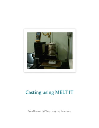
  • 8. PAGE 7 4. One should always allow metal to flow from one side of mould to other. So metal drop should be made at one side. And slowly molten metal will flow in other parts by it’s own. This prevents trapping of air bubble. It should also be ensured that molten metal is directly dropped over mould part which has got sufficient area. This is reason I poured the metal at the center. 5. One thing should be ensured that sufficient metal has been melt to do casting. Though we do not have proper control over metal flow, we can use plunger to control this to some extent. Anyways extra metal will fall over cavity area which will be taken care of in finishing. 6. Let the metal cool for 30min. . Take out metal from POP. Mostly POP mould will break in the process. Put metal in water to cool down. Melting machine setup. 1. Thermometer rod inserted in crucible. 2. Rod connected to plunger. On lifting this up a small hole is opened in the crucible and metal is poured. 3. Crucible made up of graphite. Between crucible and copper rods refractory material (white part) is provided. 4. Copper rods carrying current. 5. Mould just below the plunger. 6. Sand in tray to avoid metal to fall below in case of explosion. 7. Thermometer. 8. Computer controlling frequency.
  • 9. PAGE 8 Molten metal in crucible with plunger Flowing metal (golden colored line)
  • 10. PAGE 9  Extra metal over mould.  One of the drawbacks of open casting.  Will be removed while finishing. Casted metal STAGE 4- FINISHING After the metal has been casted it needs to be given proper finishing. Casting will be followed by frettling (sanding), straightening, machining. In general, the castings must first be removed from the tree assembly they were cast with. And then finishing steps are started. Steps in finishing:- 1. Start with removing the extra metal. One can use milling machine or just cut off the extra parts using a saw. Aluminum is not hard to cut. 2. Now if the surface is flat filing is done using a metal filer. Alternatively if surface is not flat, as in my case, one can give a finish by milling machine using flat drill bits. 3. Now surface should be sanded using sand paper.
  • 11. PAGE 10 Milling machine in action using a flat drill Job after finish. Encountered a crack at edge, probably because of low strength at edges
  • 12. PAGE 11 STAGE 5- TESTING Hardness testing and dye testing are two important test to be conducted after finishing. While hardness test can be done before or after finishing, dye test should be done after finishing. Hardness testing. Hardness test are done on sophisticated hardness testing machine. These machines have indenter which makes a micro level dent on surface of material and predicts the hardness. Machine used was “HMV-G, Micro –Vickers Hardness Tester”. Steps in hardness testing:- 1. Indenter needs flat surface to make dent. So if we are testing before finishing, as in my case, we will need to file the surface here and there thus creating some local flat surface. Hardness is an intrinsic property so it doesn’t matter whether it is done before or after finishing step. 2. Put the job on machine platform. This machine is controlled by computer. Machine has a microscope and an indenter, both computer controlled, which helps in making dent. First using micro scope find a flat surface on job. Now we set the amount of load and holding time for indent. Make indenter to approach job & make dent. Once dent is made all the data are received on computer (see table below). 3. Received data is analyzed, average hardness is calculated. One thing should be kept in mind that indentation on edges will give relatively low hardness. Those data can be ignored. And finally average hardness is compared to available data of used material. 4. In my case hardness came out to be 110.0356 HV (Vickers Pyramid number), which is comparable to data already available for aluminum. 5. Following link contains hardness of different aluminums alloys for comparison. http://asm.matweb.com/search/SpecificMaterial.asp?bassnum=MA2024T4 http://asm.matweb.com/search/SpecificMaterial.asp?bassnum=MA6061t6 Hardness testing machine
  • 13. PAGE 12 DATA FROM HARDNESS TESTING No. Test Load Duration time Lens Hardness(HV) Comment 1 HV0.05(490.3mN) 20 X40 0 Indenter could not penetrate surface 2 HV0.05(490.3mN) 30 X40 157.121 Increased holding time to 30sec 3 HV0.05(490.3mN) 30 X40 130.879 4 HV0.05(490.3mN) 30 X40 72.3546 Indent was not proper,so this value can be ignored 5 HV0.05(490.3mN) 30 X40 109.987 6 HV0.05(490.3mN) 30 X40 103.006 7 HV0.1(980.7mN) 20 X40 96.5072 Load was doubled & time was reduced to 20sec 8 HV0.1(980.7mN) 20 X40 95.6848 9 HV0.1(980.7mN) 20 X40 69.6596 Indent was not proper,so this value can be ignored 10 HV0.1(980.7mN) 20 X40 100.6 11 HV0.1(980.7mN) 20 X40 86.5 12 HV0.1(980.7mN) 20 X40 75.8 Indent was not proper,so this value can be ignored Max. 157.121 Min. 72.3546 Mean: 99.8272 Considering all values Mean : 110.0356 Considering only 8values Indent on job (image- X40)
  • 14. PAGE 13 Dye testing Dye testing is for smooth surfaces i.e when finishing step is over. This step is useful in identifying surface cracks, thus indicating about quality of cast. This test was not conducted because of non- availability of testing chemicals. Steps in dye testing:- 1. Pre-cleaning: The test surface is cleaned to remove any dirt, paint, oil, grease or any loose scale that could either keep penetrant out of a defect, or cause irrelevant or false indications. Surface can be cleaned with acetone. 2. Applying Penetrant: Now apply penetrant in ample amount all over the surface. Now let it dry for 20- 30 min. 3. Removal of excess of penetrant: Water is used to remove excessive penetrant. Water pressure should not be so high that it removes dye from cracks. Water is to be applied gently. Now remove water with a dry cloth. 4. Apply Developer: Now a white developer is applied all over the surface. Developer draws out the dye from the cracks. This is called bleed out of surface. Thus with naked eye one can identify the orientation of cracks or any other defects. PRO AND CONS OF MELT IT Pro 1. Melt is really easy to handle and setup. It uses a two phase current supply. This makes it perfect for use at any place. 2. MELT IT is small and can be moved from one place to another very easily. 3. It has additional options like choosing frequency. Thus having a better control over the amount of heat supplied. 4. To pour metal one need not take out crucible. Metal can be poured while crucible is still attached to copper rods. Thus making it very safe to handle. 5. Slag is a common problem encountered in casting. Slag gets accumulated at the top of molten metal. But while using “MELT IT” we pour metal from below of crucible by opening plunger. So slag problem is very efficiently handled here. Whereas this use to be a great problem in conventional furnace as metal is poured from top of crucible. Cons 1. This machine does not have a temperature based heat supply controller. In conventional box furnaces one can set the temperature and heat supply stops when that temperature is reached. But here we have to put an external thermometer and switch off the machine when required temp. is reached. Thus one needs to continuously monitor the thermometer.
  • 15. PAGE 14 2. There is no metal flow control. While casting we have to pour in extra metal even when undesired. Introduction of a mechanical system which could control the molten metal flow will make this machine great. Plunger does not provide proper control over metal flow. CONCLUSION Project covers all the process right from pattern making to testing. At every stage there is surely some alternative. These alternatives may produce better result. But all those process has been taken up which could be done easily, for which proper materials were available. For example closed casting has not been tried. Reason for this is that closed casting with POP is difficult task but it is not the case with sand mould. Also one can try close casting only when open casting has been mastered. So overall 1. This project produces a guideline to inexperienced people in casting. With this document as a guideline one will be able to do casting by his own without any help 2. Project also declares “MELT IT” fit for use in colleges. Surely there are certain aspects that has not been tested. For example the intricacy of casting that can be achieved. But even then this machine is a lot superior to conventional furnaces. 3. Methods practiced in this project is so friendly that one can do most of them at their home. Thus “MELT IT” can also be used by commoners at their home. 4. Throughout this project a lot of challenges were faced, some easy and some really tough. Most of them have been solved. This project also emphasizes on how to deal with these challenges. Thus making casting easier and safe. ACKNOWLEDGEMENT I have taken efforts in this project. However, it would not have been possible without the kind support and help of many individuals and organizations. I would like to extend my sincere thanks to all of them. I would specially like to thanks Dipankar sir as he gave me chance to work on this project. I would also like to express my special gratitude to Deepak, Himanshu, Abhijit and treelabs team for their guidance and support. BIBILIOGRAPHY Wikipedia and Youtube Online resources. Casting Lab Manual, IIt Bombay ‘Metal Casting, Computer-Aided Design And Analysis’. B.Ravi, IIT Bombay.