Downloaded 2,026 times

![[image courtesy:-www.engr.ku.edu]
RESIN TRANSFER MOLDING (RTM](https://image.slidesharecdn.com/y9he9rkhtvclqvgomnwm-signature-ae447a85cdf7452ab40b675cbe02036c11a196a1d748943bd6bb5b48496f4260-poli-141116104322-conversion-gate02/85/FIBER-REINFORCED-PLASTICS-FRP-17-320.jpg)
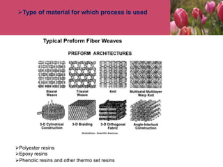
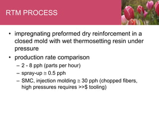
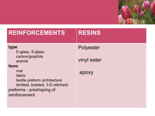
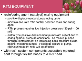
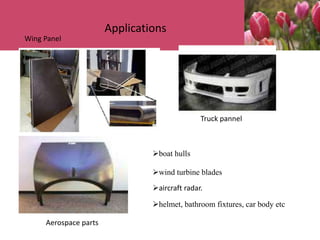
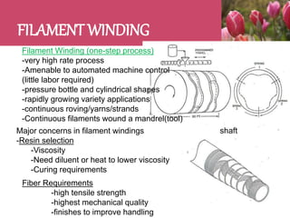
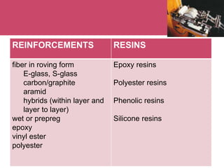
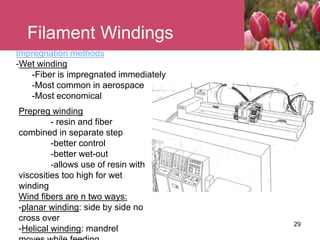


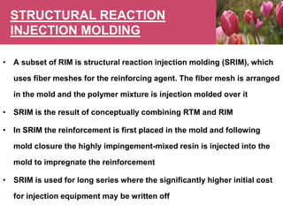


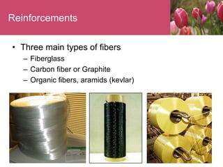
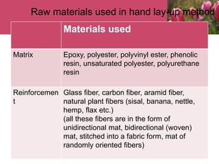
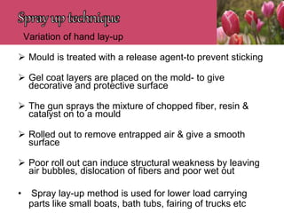
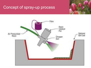
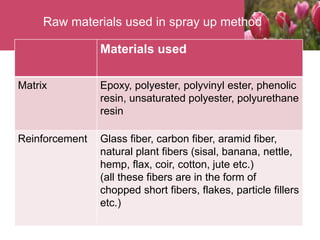
The document discusses various fiber reinforced plastic (FRP) composite manufacturing processes. It defines FRP composites and describes common matrix materials like thermoset and thermoplastic resins. Manufacturing methods covered include hand lay-up, spray-up, resin transfer molding (RTM), filament winding, pultrusion, matched-die molding, and reaction injection molding (RIM). Each process is explained along with associated materials, equipment, advantages, disadvantages and applications.


