Presentation constructing an information panel
•Download as PPTX, PDF•
0 likes•1,226 views
A short presentation showing how to construct an information panel for a technical drawing at City of Glasgow College
Report
Share
Report
Share

Recommended
introduction to engineering graphics
This document provides an introduction to engineering drawing and summarizes the key tools and concepts. It discusses what engineering drawing is and its importance for clearly explaining objects. It then lists and describes common drawing instruments like the drawing board, T-square, protractor, scale, templates, and French curves. It also covers different sizes of drawing paper and pencils commonly used for technical drawings.
7th pre alg -l20
This document contains notes from a math lesson on triangles. It defines different types of triangles based on their angles and sides, including acute, right, obtuse, equilateral, isosceles, and scalene triangles. It also provides the formula for calculating the area of a triangle using base and height, and states that the sum of the interior angles of any triangle is always 180 degrees. Examples of different triangle types are provided at the end.
C14 ee-107-engg drawing
This document contains instructions for an engineering drawing examination with two parts - Part A and Part B. Part A contains 4 questions worth 5 marks each, requiring skills like lettering, dimensioning, construction of shapes. Part B contains 4 questions worth 10 marks each involving more complex multi-view drawing of objects like prisms, cylinders based on cut section views and development of surfaces. The document provides guidance on time duration, marking scheme and expectations in terms of neatness and dimensioning from the candidates.
Illustrations trends and styles
A presentation preparing for our studio (Make it Clear) mapping current illustration trends and styles.
PRESENTATION SCRIPT
FLAT DESIGN
One of the most used llustration style of the last years, is flat design.
Flat design began as a sort of rebellion against the popular design style of skeuomorphism that isbased on 3D effects to copy the real-life properties of 3D objects as a way to use familiarity to help the user experience. The first step to boosting flat popularity in digital products was taken by Microsoft presenting new flat and minimalist style of their products in early 2000s for Windows Phone 7. Also Apple, a huge proponent of skeuomorphic design, decided, in 2012, to abandon skeuomorphism, with a new design based on the
principles of flat graphic.
FLAT DESIGN principles include:
• simplicity of shapes and elements
• minimalism
• functionality
• bold and highly readable typography
• bright colours
• avoiding textures, gradients and complex forms
• geometric approach
however the completely absence of gradients, shadows, and texture wasn’t very appropriate on usabilityand for this reason there was a transition from flat design to flat 2.0
Flat 2.0 break the hard rules associated with flat design bringing back
• Highlights
• Gradient
• Multiple tints
• Drop shadow
• Any color palette (not just super bright)
We all know the Material design guidelines introduced by Google. The visual language is characterized by “deliberate color choices, edge-to-edge imagery, large-scale typography, and intentional white space”. Some are referring to material design as “Flat 2.0” because, in many ways, it’s an update to the flat design trend, adding light/shadow, depth, and movement for a more tactile sense of realism.
HAND DRAWN ILLUSTRATIONS
Graphics that are hand-drawn, or that appear to be hand-drawn, add a human touch that sometimes you can’t have with flat design. They convey the people behind a brand, and are effective at reminding of nostalgia and a reminiscence of childhood in their simplicity.
3D ILLUSTRATIONS
3D is definitely heading our way and we are going to see its influence in all design fields. With the VR/ AR (Virtual reality bring us some place else - Augmented reality takes our current reality and adds something to it. It does not move us elsewhere) revolution rapidly building momentum, this domain is evolving pretty fast.
3D Illustration have gained immense popularity due to online gaming and CGI movies (Computergenerated imagery). 3D visuals add liveliness to a visual by giving it a character and this kind of tangibility is hardly possible in a 2D visual.
OVERLAPPING TEXT AND IMAGES
We can see this kind of graphic for a lot of staffs, identity, brands, posters. It’s pretty much a staple in the world of graphic design at the moment. Sometimes text is mixed with photography other times with illustrations or even bothtogether. Big and daring fonts will be used to grab the eye.
Multiplying polynomials powerpoint
This document provides steps for multiplying a binomial and a trinomial. It instructs to draw a grid and write the terms along the top and sides. Then multiply corresponding terms and write the results in order of descending exponents. Finally, combine like terms to get the final product.
Unit v isometric projection
introduction of engineering graphics ,projection of points,lines,planes,solids,section of solids,development of surfaces,isometric projection,perspective projection
C 14-met-mng-aei-107-engg drawing
This document contains instructions for an engineering drawing examination consisting of two parts - Part A and Part B. Part A contains 4 questions worth 5 marks each, testing basic technical drawing skills like lettering, redrawing figures with dimensions, and constructing regular shapes. Part B contains 4 questions worth 10 marks each, involving more complex multi-view drawing questions like drawing curve traces, projections of 3D shapes, extracting views from incomplete drawings, and developing surfaces of truncated cones. The document provides details of the exam format, instructions for each part, and examples of the type of technical drawing questions that will be asked.
Exterior angles of a polygon
This document outlines an activity to verify that the sum of the measures of the exterior angles of any polygon is always 3600. The activity involves drawing examples of different polygons on glaze paper, extending the sides to form the exterior angles, cutting out the interior angles and rearranging them to form a full circle by joining them to the exterior angles. Through this process, it is observed that the exterior angles always sum to 3600 when rearranged, verifying the principle for polygons.
Presentation template making equipment
Squares, steel rules, scribers, steel dividers, and beam compasses are essential measuring and marking tools for creating templates. Squares ensure perpendicular lines while steel rules offer accuracy. Scribers score sheet metal and dividers mark curves. Beam compasses reach larger radii. Snips remove waste but files accurately reduce templates to working lines using various shapes and sizes of files. Steel wool and permanent markers provide finishing touches by cleaning and clearly marking templates.
Student induction 2013-14
This document provides information for students starting a two-year stonemasonry apprenticeship program. It outlines that students will learn skills in both the classroom and workshop to develop their abilities as stonemasons. Safety equipment requirements are listed for both the workshop and classroom. The document also introduces the teaching staff and provides the course timetable and calendar.
Snecked rubble step by step angled
This presentation provides step-by-step instructions for constructing a snecked rubble wall with angled internal and external returns. The bonding pattern depends on having stones of certain lengths, so the exact wall may not be replicable, but a similar arrangement should be possible. The goal is to instruct stonemasons on building this type of structured rubble wall.
Chisels
This document provides information about masonry chisels, including their parts, materials, manufacturing, types, uses, sharpening, and suppliers. Standard masonry chisels have a high carbon steel shaft and head with a tungsten carbide tip and are available in various sizes. Bullnose chisels have a curved tip for cutting curved mouldings, while fishtail chisels have a waisted shape for carving intricate details. Granite and marble chisels are heavier duty due to the hardness of the materials they cut. Chisels can be sharpened manually or mechanically to keep their tips sharp.
It legislation
A very basic introduction to legislation in Information Communication Technology designed for learners with little or no knowledge of IT.
Cutting a Return head
A presentation covering the basic information relating to cutting a return head on a block of sandstone.
Silica dust
This document provides health and safety advice for stonemasons regarding silica dust. It discusses how respirable crystalline silica (RCS) is found in many types of rock and stone. Exposure to RCS dust particles can lead to serious lung diseases like silicosis and lung cancer. The highest risk is from freshly fractured fine RCS particles generated during tasks like drilling, cutting, and grinding. The current workplace exposure limit for RCS is 0.1mg/m3. Control methods include suppressing, collecting, and containing dust through techniques like water sprays, ventilation, and encapsulation. Respiratory protective equipment is also important but should only be used as a last resort. Maintaining controls and conducting
Presentation types of template
Joint and reverse templates are used to mark straight joints and check return moulds, respectively. Face templates mark faces without mouldings, such as on arch stones, while bed templates mark mouldings on top and bottom beds of stones like columns. Cover templates indicate moulds that do not run the full length of the stone. Wrap around templates are for curved surfaces. Raking/stretch templates are used for moulds applied to sloped joints which stretch the template from the original.
Checks and splays
This document provides instructions for stonemasons on cutting checks and splays in stone. It outlines the steps to mark and cut a check, which involves scribing lines, setting joints with a chisel, cutting a V shape, pitching along the face, setting marginal drafts, and chiseling out the rest of the check. It also details how to cut a splay, including marking splay lines on the joints and face, making the lines safe with a chisel, pitching the joints, setting in joints with marginal drafts, roughing out the center section, chiseling it flat, and polishing for a fine finish if the splay will be visible.
Template materials
Zinc, semi-rigid plastic sheet, plastic, hardboard, and cardboard are common materials used to make stonemason templates. Zinc is the most durable but also the most expensive. Semi-rigid plastic sheet is inexpensive and flexible but not suitable for repeated use. Plastic and hardboard are durable options but require specialized suppliers. Cardboard is inexpensive but not durable when wet. The document provides details on the properties of each material and examples of suitable and unsuitable uses.
Hand arm vibration
Regular exposure to hand-arm vibration from operating power tools can lead to permanent health effects like hand-arm vibration syndrome. Prolonged exposure can cause numbness, tingling, and vibration white finger. Early symptoms should not be ignored, as damage can become permanent and affect manual ability if left unchecked. Employers must assess risk, control exposure, and provide health surveillance for workers regularly exposed above the action value.
Concrete Block Walling
This document provides information on block walling, including its advantages, standard dimensions, weights, terminology, classifications, bonding arrangements, structural stability, damp proof courses, expansion joints, compressive strength, tolerances, uniform beds and joints, and brick identification, dimensions, classifications, building to gauge, racking back, return corners, toothing, bonds, and construction steps. Block walling is a versatile, durable, and cost-effective building method that provides fire resistance, sound insulation, and inherent thermal mass.
Presentation for kpt6044 t1
The document discusses a study conducted on the barriers faced by teachers in integrating ICT into mathematics lessons. The study used surveys distributed to 111 teachers during a mathematics training course. The surveys aimed to understand the applications most commonly used by teachers and how they are used. The findings showed that graphical visualization tools and online demonstrations are most useful as they make teaching easier and help students learn better. The study also found that training should be an integral part of teacher professional development and that an easy-to-use e-portal could help reduce barriers to using ICT in mathematics lessons.
Open semantic linked data
Le slide discusse da ronald ashri nel corso del webinar organizzato da dati.gov.it sul tema dei linked open data
Site conference powerpoint
This study examined the impact of cartoon technology on third grade reading comprehension. A class of 23 students were given pre- and post-tests on two passages, with one taught traditionally and one incorporating a teacher-made Pixton cartoon to review sequencing. Both methods improved comprehension significantly, but there was no significant difference between the two. However, students were engaged by the cartoon supplement, which appealed to multiple learning styles. While not conclusive, cartoon technology shows potential as a teaching tool.
Essays logo Igor Rafailov
This document tests different logo designs for "IGOR RAFAI love" by displaying 7 versions with slight variations and asks the recipient to provide feedback on which design is most attractive. It was sent by Igor Rafailov who can be contacted via email or WhatsApp for more information.
Medweb’s Telemedicine Solution
A telemedicine expert with extensive experience in the United States and abroad, Dr. Peter “Pete” Killcommons serves as the CEO of Medweb, a medical imaging and telemedicine firm he founded. Also a sought-after speaker, Dr. Peter Killcommons was the keynote presenter at the First Armenian International Telemedicine Congress, during which he donated a Medweb telemedicine system to the Armenian Telemedicine Association
Slide using and communicating technical information
The document provides information on engineering drawings and technical documentation standards. It discusses the different types of drawings and views used, including orthographic projections, section views, assembly drawings, and pictorial drawings. It also covers important drawing conventions like dimensioning, tolerancing, fits and limits according to British standards like BS 8888. Key information to include on title blocks is also outlined.
Notes-Engineering-Graphics-and-Design-1-.pdf
The document provides an overview of an engineering drawing lecture that covers geometric constructions. It discusses the basic geometric primitives of points, lines, and curves. It explains how to construct lines, arcs, and curves that are tangent to other lines and curves. It also describes how to divide a line into equal parts, construct regular polygons of a given side length, inscribe a circle inside a polygon or inscribe a polygon inside a circle. The lecture aims to teach students how to construct basic geometric shapes that serve as building blocks for more complex shapes.
More Related Content
Viewers also liked
Presentation template making equipment
Squares, steel rules, scribers, steel dividers, and beam compasses are essential measuring and marking tools for creating templates. Squares ensure perpendicular lines while steel rules offer accuracy. Scribers score sheet metal and dividers mark curves. Beam compasses reach larger radii. Snips remove waste but files accurately reduce templates to working lines using various shapes and sizes of files. Steel wool and permanent markers provide finishing touches by cleaning and clearly marking templates.
Student induction 2013-14
This document provides information for students starting a two-year stonemasonry apprenticeship program. It outlines that students will learn skills in both the classroom and workshop to develop their abilities as stonemasons. Safety equipment requirements are listed for both the workshop and classroom. The document also introduces the teaching staff and provides the course timetable and calendar.
Snecked rubble step by step angled
This presentation provides step-by-step instructions for constructing a snecked rubble wall with angled internal and external returns. The bonding pattern depends on having stones of certain lengths, so the exact wall may not be replicable, but a similar arrangement should be possible. The goal is to instruct stonemasons on building this type of structured rubble wall.
Chisels
This document provides information about masonry chisels, including their parts, materials, manufacturing, types, uses, sharpening, and suppliers. Standard masonry chisels have a high carbon steel shaft and head with a tungsten carbide tip and are available in various sizes. Bullnose chisels have a curved tip for cutting curved mouldings, while fishtail chisels have a waisted shape for carving intricate details. Granite and marble chisels are heavier duty due to the hardness of the materials they cut. Chisels can be sharpened manually or mechanically to keep their tips sharp.
It legislation
A very basic introduction to legislation in Information Communication Technology designed for learners with little or no knowledge of IT.
Cutting a Return head
A presentation covering the basic information relating to cutting a return head on a block of sandstone.
Silica dust
This document provides health and safety advice for stonemasons regarding silica dust. It discusses how respirable crystalline silica (RCS) is found in many types of rock and stone. Exposure to RCS dust particles can lead to serious lung diseases like silicosis and lung cancer. The highest risk is from freshly fractured fine RCS particles generated during tasks like drilling, cutting, and grinding. The current workplace exposure limit for RCS is 0.1mg/m3. Control methods include suppressing, collecting, and containing dust through techniques like water sprays, ventilation, and encapsulation. Respiratory protective equipment is also important but should only be used as a last resort. Maintaining controls and conducting
Presentation types of template
Joint and reverse templates are used to mark straight joints and check return moulds, respectively. Face templates mark faces without mouldings, such as on arch stones, while bed templates mark mouldings on top and bottom beds of stones like columns. Cover templates indicate moulds that do not run the full length of the stone. Wrap around templates are for curved surfaces. Raking/stretch templates are used for moulds applied to sloped joints which stretch the template from the original.
Checks and splays
This document provides instructions for stonemasons on cutting checks and splays in stone. It outlines the steps to mark and cut a check, which involves scribing lines, setting joints with a chisel, cutting a V shape, pitching along the face, setting marginal drafts, and chiseling out the rest of the check. It also details how to cut a splay, including marking splay lines on the joints and face, making the lines safe with a chisel, pitching the joints, setting in joints with marginal drafts, roughing out the center section, chiseling it flat, and polishing for a fine finish if the splay will be visible.
Template materials
Zinc, semi-rigid plastic sheet, plastic, hardboard, and cardboard are common materials used to make stonemason templates. Zinc is the most durable but also the most expensive. Semi-rigid plastic sheet is inexpensive and flexible but not suitable for repeated use. Plastic and hardboard are durable options but require specialized suppliers. Cardboard is inexpensive but not durable when wet. The document provides details on the properties of each material and examples of suitable and unsuitable uses.
Hand arm vibration
Regular exposure to hand-arm vibration from operating power tools can lead to permanent health effects like hand-arm vibration syndrome. Prolonged exposure can cause numbness, tingling, and vibration white finger. Early symptoms should not be ignored, as damage can become permanent and affect manual ability if left unchecked. Employers must assess risk, control exposure, and provide health surveillance for workers regularly exposed above the action value.
Concrete Block Walling
This document provides information on block walling, including its advantages, standard dimensions, weights, terminology, classifications, bonding arrangements, structural stability, damp proof courses, expansion joints, compressive strength, tolerances, uniform beds and joints, and brick identification, dimensions, classifications, building to gauge, racking back, return corners, toothing, bonds, and construction steps. Block walling is a versatile, durable, and cost-effective building method that provides fire resistance, sound insulation, and inherent thermal mass.
Presentation for kpt6044 t1
The document discusses a study conducted on the barriers faced by teachers in integrating ICT into mathematics lessons. The study used surveys distributed to 111 teachers during a mathematics training course. The surveys aimed to understand the applications most commonly used by teachers and how they are used. The findings showed that graphical visualization tools and online demonstrations are most useful as they make teaching easier and help students learn better. The study also found that training should be an integral part of teacher professional development and that an easy-to-use e-portal could help reduce barriers to using ICT in mathematics lessons.
Open semantic linked data
Le slide discusse da ronald ashri nel corso del webinar organizzato da dati.gov.it sul tema dei linked open data
Site conference powerpoint
This study examined the impact of cartoon technology on third grade reading comprehension. A class of 23 students were given pre- and post-tests on two passages, with one taught traditionally and one incorporating a teacher-made Pixton cartoon to review sequencing. Both methods improved comprehension significantly, but there was no significant difference between the two. However, students were engaged by the cartoon supplement, which appealed to multiple learning styles. While not conclusive, cartoon technology shows potential as a teaching tool.
Essays logo Igor Rafailov
This document tests different logo designs for "IGOR RAFAI love" by displaying 7 versions with slight variations and asks the recipient to provide feedback on which design is most attractive. It was sent by Igor Rafailov who can be contacted via email or WhatsApp for more information.
Medweb’s Telemedicine Solution
A telemedicine expert with extensive experience in the United States and abroad, Dr. Peter “Pete” Killcommons serves as the CEO of Medweb, a medical imaging and telemedicine firm he founded. Also a sought-after speaker, Dr. Peter Killcommons was the keynote presenter at the First Armenian International Telemedicine Congress, during which he donated a Medweb telemedicine system to the Armenian Telemedicine Association
Viewers also liked (20)
Similar to Presentation constructing an information panel
Slide using and communicating technical information
The document provides information on engineering drawings and technical documentation standards. It discusses the different types of drawings and views used, including orthographic projections, section views, assembly drawings, and pictorial drawings. It also covers important drawing conventions like dimensioning, tolerancing, fits and limits according to British standards like BS 8888. Key information to include on title blocks is also outlined.
Notes-Engineering-Graphics-and-Design-1-.pdf
The document provides an overview of an engineering drawing lecture that covers geometric constructions. It discusses the basic geometric primitives of points, lines, and curves. It explains how to construct lines, arcs, and curves that are tangent to other lines and curves. It also describes how to divide a line into equal parts, construct regular polygons of a given side length, inscribe a circle inside a polygon or inscribe a polygon inside a circle. The lecture aims to teach students how to construct basic geometric shapes that serve as building blocks for more complex shapes.
Introduction to Engineering Drawing
Basics of Mechanical Drawing,Necessary Instruments, various Line convention, scale of drawing are discussed.
Drawing presentation 2015 2016
This document provides an overview of engineering drawing topics including:
- Drawing instruments such as pencils, rulers, set squares, protractors, and compasses.
- Types of lines, lettering, dimensioning, and scales used in drawings.
- Plane geometry, conic sections, projections, sections of solids, and development of surfaces.
- Standards for drawings including title blocks with information like scales, dates, and part numbers.
- Methods of dimensioning including types of dimensions, arrangement of dimensions, and principles.
Designing buildings on the computer
The document describes Evan Designs Model Builder software, which allows users to design scale model buildings and structures on their computer. Key features of the software include the ability to select from various building materials like brick, windows, doors and roofing options. The document provides step-by-step instructions for using the software to design a sample two-story cafe building and narrow gauge railroad office in HO scale. Basic supplies needed and cutting/assembly techniques are also outlined.
introductiontoengineeringgraphics-170307045101.pdf
An engineering drawing is a technical drawing that clearly defines and communicates a design. It is used for collaboration, procurement, manufacturing, and quality control. The document discusses the role of graphics in visualization, communication, and documentation. It provides examples of engineering drawing applications in construction, manufacturing, and ships. The document also covers drawing instruments, types of lines, dimensioning, lettering, and scales used in engineering drawings.
Engineering-Graphics- Basics- (1).pdf
The document provides an overview of engineering graphics and drawings. It discusses how graphics are used to effectively communicate technical information through diagrams and illustrations. The summary includes:
1) Engineering drawings use lines and geometric shapes to represent objects through different views and perspectives in a standardized way. This graphical language allows for clear and concise communication.
2) Traditional and computer-aided drawing tools and methods are used to precisely construct drawings according to international standards for scale, layout and line types.
3) Effective lettering and annotation is important for conveying additional details and specifications in a uniform and legible manner on drawings.
1.engineering graphics- basics-engineering108.com
This document provides an overview of engineering graphics and drawings. It discusses how graphics are used to effectively communicate technical information through diagrams and drawings. Key topics covered include the components of graphics language, different drawing tools and methods, standards for drawings, basic line types, lettering guidelines, and principles of geometry construction. The goal is to introduce basic concepts for creating clear and precise engineering drawings.
Introduction to engineering graphics
An engineering drawing is a technical drawing that clearly defines and communicates a design. It is used for collaboration, procurement, manufacturing, and quality control. The document discusses the role of graphics in visualization, communication, and documentation. It also provides examples of engineering drawing applications in construction, manufacturing, and ships. Key aspects like types of lines, dimensioning, lettering, and scales are explained.
3._Drawing_Standards.ppt
Drawing standards specify sizes for drawing sheets from A0 to A4, with successive smaller sizes having the same length to width ratio. Drawings should include a title block with information like the sheet size and scale. Different line types like continuous, dashed and center lines are used to represent visible, hidden and symmetrical features. Dimensions are expressed without units and placed outside views to fully describe components. Standard lettering sizes and styles are specified to ensure legibility.
Dimensioning unit 2
This document provides guidelines for dimensioning engineering drawings in 3 sentences:
Dimensioning involves specifying an object's size, location, material, and other information using extension lines, dimension lines, leader lines, and notes to facilitate manufacturing and measurement. Key guidelines include placing dimensions outside views for clarity, using aligned or unidirectional methods for dimension figures, and noting radii, holes, chamfers, and rounded ends according to manufacturing needs. The document demonstrates best practices and common mistakes to avoid for clear and complete dimensioning of drawings.
Introduction to engineering graphics
1. Engineering drawing is a technique to create graphical representations containing dimensions, specifications and notes to transform abstract concepts into real world objects. It is used in industries like shipping, manufacturing and construction.
2. There are two main types of projection in engineering drawing: parallel projection and perspective projection.
3. Key tools used in engineering drawing include a T-square, compass, French curves, drafter, protractor, set square, pencils, triangles and scales. Accuracy, speed, legibility and neatness are important objectives.
Lecture week 5
This document discusses the types of lines used in engineering drawings including visible lines, hidden lines, center lines, and dimension and extension lines. It describes the purpose of dimensioning drawings to fully define the size, location, finish and other requirements for manufacturing. Key aspects of dimensioning covered include using size and location dimensions, dimensioning features like holes, arcs, cylinders, chamfers and rounded ends according to manufacturing methods, and following practices for placement of dimensions, leaders, extension lines and dimension figures.
Introduction to engineering graphics
1) The document provides an introduction to engineering graphics and drawing instruments. It discusses the basic concepts of engineering drawing including projection types and scales. 2) It then describes various drawing tools such as T-squares, compasses, protractors, set squares, and their uses. 3) The document also explains guidelines for sheet layout including title blocks, borders, margins and scale usage in engineering drawings.
Lecture week 5
This document discusses guidelines for dimensioning engineering drawings. It describes the different types of lines used such as visible lines, hidden lines, center lines, and dimension and extension lines. It explains why dimensioning is important for manufacturing interchangeable parts. The key components of dimensioning are described, including extension lines, dimension lines, leader lines, and dimension figures. Guidelines are provided for placement of dimensions, such as not crossing lines and placing dimensions outside the view. Dimensioning various shapes such as arcs, holes, cylinders, and rounded ends are also covered.
Industrial pattern making
Industrial pattern making is the process of creating templates used to manufacture export readymade garments. It involves translating 2D design sketches into 3D patterns with markings to precisely assemble the garment pieces. It requires an understanding of measurements, body proportions, and buyer specifications. Industrial pattern makers examine designs, trace outlines, mark patterns, and grade patterns for different sizes. The patterns are used to produce sample garments and are adjusted through fittings until perfected. Precise pattern making is essential for apparel production and ensuring quality garments that buyers continue ordering.
basicsofengineeringdrawingbyrishabhnatholia-161225130645.pdf
The document discusses key concepts in engineering drawing including chapters on drawing standards, sheets, tools, scales, lines, lettering, projection, sectioning and dimensioning. It provides explanations and examples of each topic. The introduction defines an engineering drawing as a technical drawing used to fully define engineered items according to standardized conventions for layout, symbols, size etc. Dimensioning is explained as providing numerical values and graphical indications of distances, sizes, positions and other details.
B.tech i eg u1 dimensioning
1) Dimensioning is the process of specifying a part's sizes, locations, material, tolerances, and other information using figures, symbols, and notes. This information is necessary to facilitate manufacturing and measurement.
2) Dimensioning components include extension lines, dimension lines, leader lines, and dimension figures. Extension lines indicate the locations being dimensioned. Dimension lines connect extension lines and contain dimension figures.
3) Proper dimensioning practices include leaving gaps between lines, placing dimensions outside views, using consistent dimensioning methods, and clearly communicating all necessary information to manufacture the part.
Basics of engineering drawing by Rishabh Natholia
This is my work to make sure it is easy to understand the basic of Mechanical Engineer Drawing.It is a made for all and a quick bite to the very basics of engineering drawing. This data will also help the students to score more in their subjects. This will also help on design sector interviews.
introductiontoengineeringgraphics-170307045101.docx
An engineering drawing is a technical drawing that clearly defines and communicates a design. It allows for collaboration in design, procurement, manufacturing, quality control, and other areas. The document then discusses various topics related to engineering drawings including types of lines, dimensioning, lettering, and scales.
Similar to Presentation constructing an information panel (20)
Slide using and communicating technical information
Slide using and communicating technical information
introductiontoengineeringgraphics-170307045101.pdf
introductiontoengineeringgraphics-170307045101.pdf
basicsofengineeringdrawingbyrishabhnatholia-161225130645.pdf
basicsofengineeringdrawingbyrishabhnatholia-161225130645.pdf
introductiontoengineeringgraphics-170307045101.docx
introductiontoengineeringgraphics-170307045101.docx
More from doogstone
Risk assessment
This document provides an introduction to risk assessment for stonemasons. It explains that a risk is the likelihood of harm from a hazard together with the severity of the harm. Common hazards in stonemasonry like angle grinders and ladders are identified. It outlines the five steps to conducting a risk assessment: identifying hazards, identifying those affected, evaluating risks and controls, recording the assessment, and reviewing it. Workers are asked to identify hazards in an image and discuss hazards from their own experience. The document instructs trainees to complete a risk assessment for cutting stone.
Health and safety signage
A short presentation covering the main points of health and safety signage in the UK for the stonemasonry industry.
Construction electrical safety
This document provides an introduction to electrical safety for stonemasons. It discusses various methods for supplying power on construction sites, including battery tools, generators, and mains power through transformers. It emphasizes the importance of using the proper cables and ensuring equipment is rated for the correct voltage. Safety devices like residual current devices (RCDs) and junction boxes are also outlined. The document provides guidance on inspecting equipment and outlines common electrical injuries and safety tips for working with electricity.
Riddor
RIDDOR are UK regulations that require work-related injuries, diseases, and dangerous occurrences be reported. The regulations aim to generate reports for authorities to examine incidents and trends and develop prevention strategies. Reportable incidents include deaths, injuries requiring over 7 days off work, dangerous occurrences, and certain work-related diseases diagnosed by a doctor. The responsible person such as an employer must make reports. An accident book must be kept to record any incidents at a construction site.
Presentation constructing a pentagon
The document provides instructions for constructing a regular pentagon using basic geometric techniques:
1) Mark a circle with center point C and diameter line AB. Mark a perpendicular line DC and point E to form a second circle.
2) Extend a line through points B and E to intersect the second circle at points F and G.
3) Mark arcs from center B with radius BG to intersect the circle at points H,J, K, and M, completing the pentagon lines.
Presentation constructing a heptagon
The document provides instructions for constructing a heptagon shape (7 sides). It details the steps of marking a central circle and diameter line, then using radius arcs to mark intersecting points to form the sides of the shape by connecting those points with lines. The final step is constructing an arc with the radius from the center point to a side point to complete the 7-sided geometric figure. The instructions were developed by the Stonemasonry Department at City of Glasgow College in 2013.
Introduction to masonry walling
This document provides an introduction to different types of stone walling techniques for stonemasons. It describes ashlar walling as dressed stone walls that are flat or have chamfered edges. Coursed rubble walling uses stones of identical bed heights on each course. Snecked rubble walling interlocks three types of stones vertically and horizontally. Random rubble walling uses stones of varying sizes arranged loosely. The document also summarizes broken coursed rubble, polygonal rubble, cladding, gabions, dry stone walling, and flint walling techniques.
Surfacefinishes12
This document provides descriptions of various surface finishes used in stonemasonry. It describes finishes such as plane faced and broached, which involve chiseling and polishing stone to remove marks. It also outlines dabbed and sparrowpecked finishes involving indentations made in patterns. Tooled and chevroned finishes are produced using chisels at angles. Bull-faced and split-faced finishes give the impression of a split stone. More intricate finishes like reticulated and vermiculated involve sinking shapes into the stone. Hammer dressing combines dabbing and a rough appearance. The finishes are used for architectural features like ashlar stonework.
Snecked rubble step by step
The document provides a step-by-step guide for constructing a snecked rubble wall with a block backing. It explains that the first course uses a repeating pattern of one riser followed by three levellers. Subsequent courses consist of arrangements built between the risers of the lower courses, with a sneck followed by a riser and two levellers. As the wall is built higher, the same bonding pattern is maintained while ensuring proper overlaps and joints between stones. Finishing steps include leveling the top course and pointing the completed wall.
Half brick walling calculations
This document provides instructions for calculating the number of courses, bricks, and total bricks needed for half brick walling projects. It explains that the number of courses for a given height can be determined using a brick dimension table. The number of bricks for a given length is also found using this table. Additionally, it notes that every square meter of half brick walling contains 60 bricks, so the total number of bricks for a wall can be calculated by multiplying the surface area by 60. Three example calculations are provided to demonstrate this process.
Cutting a cavetto mould
This document provides instructions for stonemasons on how to cut different types of mouldings, including cavetto mouldings and return moulds. It explains how to identify the elements of a cavetto moulding, set out a template to mark the moulding, and cut the moulding using chisels. It also describes how to mark and cut mitres, splays, and return moulds. The goal is to teach stonemasons the proper techniques for shaping stone to create decorative mouldings.
Cutting an ovolo mould
A short introductory presentation on how to produce an ovolo mould on sandstone using traditional tools and techniques
Rock formation
Sedimentary rock is formed from the compaction and lithification of layers of sediment over millions of years. Sandstone forms from quartz and feldspar minerals in sediment, and limestone forms from calcium carbonate from marine organisms. Igneous rock forms when magma cools and solidifies, such as granite. Metamorphic rock forms from the alteration of sedimentary or igneous rock under heat and pressure, changing the rock type, such as slate forming from shale and marble from limestone. Stone should be laid according to its natural bedding plane for maximum strength, or on its edge for overhanging features.
Manual handling
This document provides health and safety advice for stonemasons regarding manual handling. It summarizes statistics showing that lifting, handling, or carrying accounted for 16.7% of construction injuries in 2008/2009. It outlines employers' responsibilities under the Manual Handling Operations Regulations to avoid hazardous manual handling, assess risks, and reduce risks. It also outlines workers' responsibilities. The document provides guidance on manual handling training, assessing risks by considering the task, load, environment, individual capability and other factors. It provides advice on lifting safely and using mechanical lifting aids.
Chisels
This document provides information about masonry chisels. It describes the parts of a chisel including the head, shoulders, and shaft. Chisels are typically made of high carbon tool steel with a tungsten carbide tip. Different types of chisel heads and uses are outlined, including standard, bullnose, fishtail, and lettering chisels. Granite and marble chisels are designed to be more durable due to the hardness of those materials. Chisels can be sharpened manually or mechanically using grinding wheels or diamond sharpening blocks.
IT guide to data storage and protection
A very basic introduction to data storage and protection produced by the stonemasonry team at City of Glasgow College
IT hardware and software
This document provides an introduction to hardware and software components of information communication technology (ICT). It defines hardware as the physical components that make up computers, including examples like processors, storage devices, and input/output components. It also defines software as the collection of programs and data that provide computers with instructions. The document discusses common hardware components like desktop computers and mobile phones, identifying their input, output, processing, and storage functions. It also lists examples of widely-used software programs.
Percentages
This document discusses the use of percentages in the construction industry. It explains what percentages are and how they are expressed. It provides examples of using percentages to calculate VAT, discounts, and ordering additional materials to account for wastage. Percentages are commonly used in construction to indicate VAT, discounts on products, and amounts to order beyond requirements to allow for losses during projects.
Ratios
Ratios are used commonly in construction to represent proportional relationships between different components. For example, a mortar mix ratio of 5:2 indicates five buckets of sand for every two buckets of lime. Ratios can be simplified or multiplied to calculate quantities. For instance, a ratio of bricklayers to laborers of 2:1 means that one laborer services every two bricklayers. Ratios can also represent three or more components, like a mortar mix of 5:2:1 for sand, lime, and dye respectively.
Perimeters basic
This document discusses calculating perimeters of basic shapes like squares, rectangles, and triangles. It provides formulas for calculating each: the perimeter of a square is 4 times the length of one side; the perimeter of a rectangle is the sum of the lengths of all four sides; the perimeter of a triangle is the sum of the lengths of its three sides. It notes that complex shapes may require calculating the perimeters of individual components and summing them.
More from doogstone (20)
Recently uploaded
বাংলাদেশ অর্থনৈতিক সমীক্ষা (Economic Review) ২০২৪ UJS App.pdf
বাংলাদেশের অর্থনৈতিক সমীক্ষা ২০২৪ [Bangladesh Economic Review 2024 Bangla.pdf] কম্পিউটার , ট্যাব ও স্মার্ট ফোন ভার্সন সহ সম্পূর্ণ বাংলা ই-বুক বা pdf বই " সুচিপত্র ...বুকমার্ক মেনু 🔖 ও হাইপার লিংক মেনু 📝👆 যুক্ত ..
আমাদের সবার জন্য খুব খুব গুরুত্বপূর্ণ একটি বই ..বিসিএস, ব্যাংক, ইউনিভার্সিটি ভর্তি ও যে কোন প্রতিযোগিতা মূলক পরীক্ষার জন্য এর খুব ইম্পরট্যান্ট একটি বিষয় ...তাছাড়া বাংলাদেশের সাম্প্রতিক যে কোন ডাটা বা তথ্য এই বইতে পাবেন ...
তাই একজন নাগরিক হিসাবে এই তথ্য গুলো আপনার জানা প্রয়োজন ...।
বিসিএস ও ব্যাংক এর লিখিত পরীক্ষা ...+এছাড়া মাধ্যমিক ও উচ্চমাধ্যমিকের স্টুডেন্টদের জন্য অনেক কাজে আসবে ...
Hindi varnamala | hindi alphabet PPT.pdf
हिंदी वर्णमाला पीपीटी, hindi alphabet PPT presentation, hindi varnamala PPT, Hindi Varnamala pdf, हिंदी स्वर, हिंदी व्यंजन, sikhiye hindi varnmala, dr. mulla adam ali, hindi language and literature, hindi alphabet with drawing, hindi alphabet pdf, hindi varnamala for childrens, hindi language, hindi varnamala practice for kids, https://www.drmullaadamali.com
Pollock and Snow "DEIA in the Scholarly Landscape, Session One: Setting Expec...
Pollock and Snow "DEIA in the Scholarly Landscape, Session One: Setting Expec...National Information Standards Organization (NISO)
This presentation was provided by Steph Pollock of The American Psychological Association’s Journals Program, and Damita Snow, of The American Society of Civil Engineers (ASCE), for the initial session of NISO's 2024 Training Series "DEIA in the Scholarly Landscape." Session One: 'Setting Expectations: a DEIA Primer,' was held June 6, 2024.Natural birth techniques - Mrs.Akanksha Trivedi Rama University
Natural birth techniques - Mrs.Akanksha Trivedi Rama UniversityAkanksha trivedi rama nursing college kanpur.
Natural birth techniques are various type such as/ water birth , alexender method, hypnosis, bradley method, lamaze method etcReimagining Your Library Space: How to Increase the Vibes in Your Library No ...
Librarians are leading the way in creating future-ready citizens – now we need to update our spaces to match. In this session, attendees will get inspiration for transforming their library spaces. You’ll learn how to survey students and patrons, create a focus group, and use design thinking to brainstorm ideas for your space. We’ll discuss budget friendly ways to change your space as well as how to find funding. No matter where you’re at, you’ll find ideas for reimagining your space in this session.
PCOS corelations and management through Ayurveda.
This presentation includes basic of PCOS their pathology and treatment and also Ayurveda correlation of PCOS and Ayurvedic line of treatment mentioned in classics.
Leveraging Generative AI to Drive Nonprofit Innovation
In this webinar, participants learned how to utilize Generative AI to streamline operations and elevate member engagement. Amazon Web Service experts provided a customer specific use cases and dived into low/no-code tools that are quick and easy to deploy through Amazon Web Service (AWS.)
clinical examination of hip joint (1).pdf
described clinical examination all orthopeadic conditions .
Exploiting Artificial Intelligence for Empowering Researchers and Faculty, In...
Exploiting Artificial Intelligence for Empowering Researchers and Faculty, In...Dr. Vinod Kumar Kanvaria
Exploiting Artificial Intelligence for Empowering Researchers and Faculty,
International FDP on Fundamentals of Research in Social Sciences
at Integral University, Lucknow, 06.06.2024
By Dr. Vinod Kumar KanvariaThe History of Stoke Newington Street Names
Presented at the Stoke Newington Literary Festival on 9th June 2024
www.StokeNewingtonHistory.com
How to Setup Warehouse & Location in Odoo 17 Inventory
In this slide, we'll explore how to set up warehouses and locations in Odoo 17 Inventory. This will help us manage our stock effectively, track inventory levels, and streamline warehouse operations.
What is Digital Literacy? A guest blog from Andy McLaughlin, University of Ab...
What is Digital Literacy? A guest blog from Andy McLaughlin, University of Aberdeen
RHEOLOGY Physical pharmaceutics-II notes for B.pharm 4th sem students
Physical pharmaceutics notes for B.pharm students
How to Make a Field Mandatory in Odoo 17
In Odoo, making a field required can be done through both Python code and XML views. When you set the required attribute to True in Python code, it makes the field required across all views where it's used. Conversely, when you set the required attribute in XML views, it makes the field required only in the context of that particular view.
BÀI TẬP BỔ TRỢ TIẾNG ANH 8 CẢ NĂM - GLOBAL SUCCESS - NĂM HỌC 2023-2024 (CÓ FI...
BÀI TẬP BỔ TRỢ TIẾNG ANH 8 CẢ NĂM - GLOBAL SUCCESS - NĂM HỌC 2023-2024 (CÓ FI...Nguyen Thanh Tu Collection
https://app.box.com/s/y977uz6bpd3af4qsebv7r9b7s21935vdRecently uploaded (20)
বাংলাদেশ অর্থনৈতিক সমীক্ষা (Economic Review) ২০২৪ UJS App.pdf
বাংলাদেশ অর্থনৈতিক সমীক্ষা (Economic Review) ২০২৪ UJS App.pdf
Pollock and Snow "DEIA in the Scholarly Landscape, Session One: Setting Expec...
Pollock and Snow "DEIA in the Scholarly Landscape, Session One: Setting Expec...
Natural birth techniques - Mrs.Akanksha Trivedi Rama University
Natural birth techniques - Mrs.Akanksha Trivedi Rama University
Reimagining Your Library Space: How to Increase the Vibes in Your Library No ...
Reimagining Your Library Space: How to Increase the Vibes in Your Library No ...
Leveraging Generative AI to Drive Nonprofit Innovation
Leveraging Generative AI to Drive Nonprofit Innovation
Exploiting Artificial Intelligence for Empowering Researchers and Faculty, In...
Exploiting Artificial Intelligence for Empowering Researchers and Faculty, In...
How to Setup Warehouse & Location in Odoo 17 Inventory
How to Setup Warehouse & Location in Odoo 17 Inventory
Liberal Approach to the Study of Indian Politics.pdf
Liberal Approach to the Study of Indian Politics.pdf
What is Digital Literacy? A guest blog from Andy McLaughlin, University of Ab...
What is Digital Literacy? A guest blog from Andy McLaughlin, University of Ab...
NEWSPAPERS - QUESTION 1 - REVISION POWERPOINT.pptx
NEWSPAPERS - QUESTION 1 - REVISION POWERPOINT.pptx
RHEOLOGY Physical pharmaceutics-II notes for B.pharm 4th sem students
RHEOLOGY Physical pharmaceutics-II notes for B.pharm 4th sem students
BÀI TẬP BỔ TRỢ TIẾNG ANH 8 CẢ NĂM - GLOBAL SUCCESS - NĂM HỌC 2023-2024 (CÓ FI...
BÀI TẬP BỔ TRỢ TIẾNG ANH 8 CẢ NĂM - GLOBAL SUCCESS - NĂM HỌC 2023-2024 (CÓ FI...
Presentation constructing an information panel
- 1. Stonemasonry Department 2013 Prepare Templates and Moulds Constructing an Information Panel
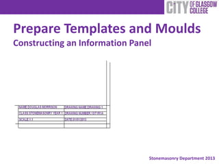
- 2. What is an Information Panel? The purpose of an information panel on a construction drawing is to relay information to whoever is reading the drawing. The information panel will generally include details on the job name and code, the architect, the draughtsman, the version and date, the elevation and the scale
- 3. Constructing the Panel: A3 Start by setting in 10mm margins on the top, bottom and right hand side of the drawing sheet. The left hand side of the sheet has a 20mm margin. This is to allow the drawing to be opened when folded and placed in a ring binder
- 4. Constructing the Panel: A3 Measure 24mm up from the bottom margin and draw a border line across the width of the page. Remember to use construction lines at this stage. 24mm
- 5. Constructing the Panel: A3 Next you should measure 70mm and 140mm from the right margin to construct the boxes containing the information panel 140mm 70mm
- 6. Constructing the Panel: A3 The panels are completed by marking a series of lines measuring 4mm apart between the border lines.
- 7. Inserting Information The information is then inserted in BLOCK CAPITAL printing with the top and bottom of each letter touching the lines. This means every letter should measure 4mm in height. YOU HAVE NOW COMPLETED YOUR INFORMATION PANEL. WELL DONE NAME:DOUGLAS MORRISON CLASS:STONEMASONRY YEAR 1 SCALE:1:1 DRAWING NAME:DRAWING 1 DRAWING NUMBER:1STYR1A DATE:01/01/2013