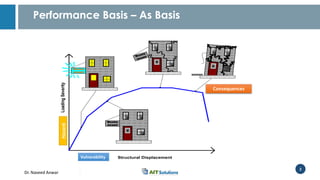
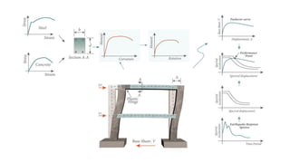
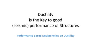
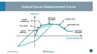
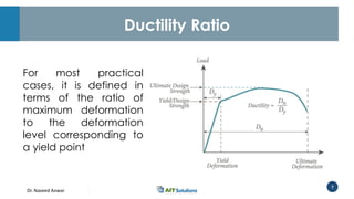
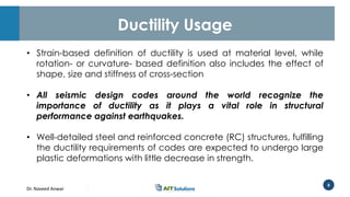
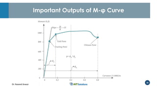
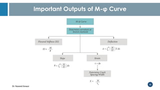
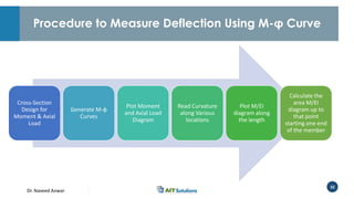
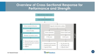
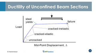
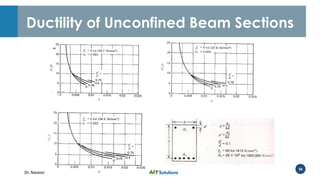
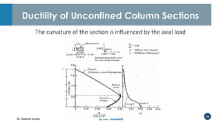
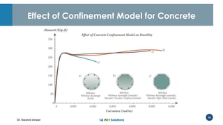
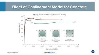
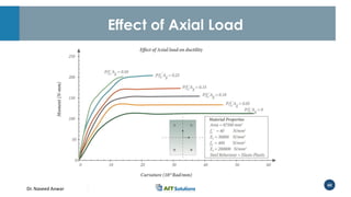
Dr. Naveed Anwar
Importance of Ductility in
Structural Performance Analysis
Design of Tall Buildings: Trends and Achievements for
Structural Performance
Bangkok-Thailand
November 7-11, 2016
Naveed Anwar, PhD
Dr. Naveed Anwar
2
Performance Basis – As Basis
Structural Displacement
LoadingSeverity
Resta
urant
Resta
urant
Resta
urant
Hazard
Vulnerability
Consequences
Dr. Naveed Anwar
3
Dr. Naveed Anwar
4
Ductility
is the Key to good
(seismic) performance of Structures
Performance Based Design Relies on Ductility
Dr. Naveed Anwar
5
Typical Force-Displacement Curve
Dr. Naveed Anwar
6
New Book
Structural Cross-sections
Analysis and Design
Naveed Anwar, Fawad Najam
Dr. Naveed Anwar
7
Ductility Ratio
For most practical
cases, it is defined in
terms of the ratio of
maximum deformation
to the deformation
level corresponding to
a yield point
Dr. Naveed Anwar
8
Ductility Usage
• Strain-based definition of ductility is used at material level, while
rotation- or curvature- based definition also includes the effect of
shape, size and stiffness of cross-section
• All seismic design codes around the world recognize the
importance of ductility as it plays a vital role in structural
performance against earthquakes.
• Well-detailed steel and reinforced concrete (RC) structures, fulfilling
the ductility requirements of codes are expected to undergo large
plastic deformations with little decrease in strength.
Dr. Naveed Anwar
9
Limitations of Strength Based Design
• Cross-sections are capable of resisting a certain value of actions
based on assumed failure criterion
• Actions are obtained often from linear elastic analysis, and are
factored to provide certain factor of safety
• Strength design itself provides no information or control on the level
of deformation produced at that factored load level
• No information about behavior of the member if loads or actions
were to exceed the factored design load
Dr. Naveed Anwar
Action Deformation Curves
Dr. Naveed Anwar
11
Action-Deformation Curves
• Relationship between action and corresponding deformation
• These relationships can be obtained at several levels
1. The Structural Level: Load - Deflection
2. The Member Level: Moment - Rotation
3. The Cross-section Level: Moment - Curvature
4. The Material Level : Stress-Strain
• The Action-Deformation curves show the entire response of the
structure, member, cross-section or material
Dr. Naveed Anwar
12
General Force-Displacement Relationship
Dr. Naveed Anwar
13
General Force-Displacement Relationship
Point ‘A’ corresponds to the serviceability design considerations and working
strength or allowable strength design concepts.
Point ‘B’ is the point up to which the relationship between load and deformation
can be considered nearly linear and the deformations are relatively small.
Point ‘C’ roughly corresponds to the ultimate strength considerations or the design
capacity consideration.
Point ‘D’ is the point at which the load value starts to drop with increasing
deformations
Point ‘E’ is the point at which the load value is reduced to just a fraction of ultimate
load (residual strength)
Dr. Naveed Anwar
14
How to Get Action-Deformation Curves
1. By actual measurements
• Apply load, measure deflection
• Apply load, measure stress and strain
2. By computations
• Use material models, cross-section dimensions to get Moment-Curvature
Curves
3. By combination of measurement and computations
• Calibrate computation models with actual measurements
• Some parameters obtained by measurement and some by computations
Dr. Naveed Anwar
15
Ductility Levels
Dr. Naveed Anwar
16
Moment Curvature Relationship
is the Key for computing
Cross-section and Member Ductility
Dr. Naveed Anwar
17
Load-Deflection & Moment Curvature Curve
Dr. Naveed Anwar
18
Moment Curvature Relationships
First Crack
First yield of steel
reinforcement
Moment M
Curvature
Moment M
Curvature
Mu
Tri-linear M- φ Relationship Idealized bilinear M- φ Relationship
Dr. Naveed Anwar
19
Moment Curvature (M-φ) Curve
• The load-deformation curves can be plotted between axial load and axial
shortening, shear force and shear deformation, moment and curvature, and
torsion and twist.
• Moment-curvature relationship is probably the most important and useful action-
deformation curve especially for flexural members such as beams, columns and
shear walls.
• Many of the design codes and design procedures or design handbooks do not
provide sufficient information for computation and use of M- relationships
Dr. Naveed Anwar
20
Determination of M-φ Curve
• The generation of moment curvature curve can be terminated
based on any number of specific conditions such as,
 The maximum specified strain is reached.
 The first rebar reaches yield stress a any other strain level
 The concrete reaches a certain strain level.
 Also, during the generation of the moment curvature curve the failure
or key response points can be recorded and displayed on the curve.
Dr. Naveed Anwar
21
Significance of Moment Curvature Curve
• Information provided by M-φ curve is very useful for non-linear
analysis of structures including the evaluation of post-elastic
behavior.
• M-φ Curve is basis for the capacity-based, and performance-
based design methods especially analysis of structures using
nonlinear static procedures as well as in determining the rotational
capacity of plastic hinges formed during high seismic activity.
Dr. Naveed Anwar
22
M-φ Curve and Stiffness
Cross-section stiffness can be obtained from the slope of
the M-φ curve. Stiffness measure this way is termed as
“Effective Stiffness”
Dr. Naveed Anwar
23
Unified Cross-section
Models
Dr. Naveed Anwar
24
The Generalized Section
Dr. Naveed Anwar
25
Generalized Equation and Response
25
 
 
 





























 



...),(
1
....,
1
...),(
1
....,
1
...),(
1
...,
1
121
3
121
2
121
1
i
n
i
ii
x y
y
i
n
i
ii
x y
x
x y
n
i
iiz
xyxAxdydxyxM
yyxAydydxyxM
yxAdydxyxN















Nz
MxMyAdvanced Concrete l August-2014
y
h
c
fc
Strain
Stresses for
concrete and
R/F
Stresses for
Steel
f1
f2
fn
fs NA
CL
Horizontal
Dr. Naveed Anwar
26
Important Outputs of M-φ Curve
Dr. Naveed Anwar
27
Important Outputs of M-φ Curve
1. Cracking Point
This point corresponds to the onset of material cracking of a cross-section. It
provides the moment and corresponding curvature for design considerations
related to start of cracking
2. Yield Point
This point corresponds to the onset of material yielding of a cross-section. It provides
the moment capacity and corresponding curvature for strength design of section.
3. Failure Point
This point corresponds to the maximum curvature and defines the maximum
deformation capacity of section.
Dr. Naveed Anwar
28
Important Outputs of M-φ Curve
4. Ductility
The ratio of ultimate curvature and yield curvature defines the section ductility.
𝜇 = 𝜙 𝑢/𝜙 𝑦
5. Stiffness of the Section at given M and 𝝓
Slope of M-𝜙 curve at any given point corresponds to the effective stiffness of the
section.
𝜙 =
𝑀
𝐸𝐼
and 𝐸𝐼 =
𝑀
𝜙
Dr. Naveed Anwar
29
Important Outputs of M-φ Curve
6. Slope of the section at given Moment
M-𝜙 curve can also be used to determine rotation at any point in a member.
𝜃 =
𝑎
𝑏
𝑀
𝐸𝐼
𝑑𝑥
7. Deflection of the section at given Moment
Δ =
𝑎
𝑏
𝑀
𝐸𝐼
𝑥 𝑑𝑥
8. Strain at given Moment
ε = 𝜙𝑐
9. Crack Width at given Spacing
𝑊 = 𝜀 𝑠 . 𝑋
𝑊 = 𝜙 𝑦 . 𝑋
Dr. Naveed Anwar
30
Important Outputs of M-φ Curve
10. Crack Spacing at given crack width
𝑋 = 𝑊/𝜀 𝑠
𝑋 = 𝑊/𝜙 𝑦
Dr. Naveed Anwar
31
Important Outputs of M-φ Curve
Dr. Naveed Anwar
32
Procedure to Measure Deflection Using M-φ Curve
Cross-Section
Design for
Moment & Axial
Load
Generate M-φ
Curves
Plot Moment
and Axial Load
Diagram
Read Curvature
along Various
locations
Plot M/EI
diagram along
the length
Calculate the
area M/EI
diagram up to
that point
starting one end
of the member
Dr. Naveed Anwar
33
Overview of Cross-Sectional Response for
Performance and Strength
Dr. Naveed Anwar
Ductility of Unconfined Beam &
Column Sections
Dr. Naveed Anwar
35
Ductility of Unconfined Beam Sections
Dr. Naveed Anwar
36
Ductility of Unconfined Beam Sections
Dr. Naveed Anwar
37
Ductility of Unconfined Column Sections
• The curvature of the section is influenced by the axial load, hence there
is no unique M-φ relationship for a given column section.
• However, it is possible to plot the combination of axial load P and
Moment M which cause the section to reach the ultimate capacity.
• It is evident that the ductility of the column section is significantly
reduced by the presence of axial load.
• The axial load levels greater than the balanced failure load, the ductility
decreases, being due only to the inelastic deformation of the concrete.
Dr. Naveed Anwar
38
Ductility of Unconfined Column Sections
The curvature of the section is influenced by the axial load
Dr. Naveed Anwar
Ductility of Confinement of RC
Sections
Dr. Naveed Anwar
40
Confinement
is the Key for Ductility in Reinforced
Concrete Members
Dr. Naveed Anwar
41
Confinement of RC Sections
Poisson’s effect for compressive force
Concrete sample wrapped with a suitably strong material
(e.g. carbon fiber), becomes impossible to crush
Dr. Naveed Anwar
42
Confinement of RC Sections
• Ductility can be improved if confining is done in such a way that the
concrete sample is allowed to expand very slowly.
• In RC members, concrete is confined using rectangular or circular steel
reinforcement hoops.
• One RC cross section have 2 types of concrete, i.e. the confined
concrete in the inner core and the cover concrete outside the core.
• Double confinement using multiple hoops is also quite common is bridges.
For RC columns, more attention is given to vertical reinforcement than
lateral reinforcement. However, most of the axial strength is contributed
by the lateral reinforcement
Dr. Naveed Anwar
43
Various types and Configurations of
Confinement
Dr. Naveed Anwar
44
Confinement Provided by Spiral Reinforcement
Spiral reinforcement is also one of the most efficient ways of
providing confinement to reinforced concrete members
Dr. Naveed Anwar
45
Confinement Provided by Spiral Reinforcement
Comparison of axial force-deformation behaviors of reinforced concrete columns
with various confinement configurations
Dr. Naveed Anwar
46
Stress-Strain Models for RC
Dr. Naveed Anwar
47
Stress-Strain Models for Confined
Concrete
Mander’s Model (1988) Kent and Park model (1971)
Dr. Naveed Anwar
48
Stress-Strain Models for Confined Concrete
Mander’s
stress-strain
Model
(1988)
Kent and
Park stress-
strain model
(1971)
Scott et al.
stress-strain
model
(1982)
Yong et al.
stress-strain
model
(1989)
Bjerkeli et al.
stress-strain
model
(1990)
Li et al.
stress-strain
model
(2000)
Dr. Naveed Anwar
49
Steel Reinforcement Behavior
Dr. Naveed Anwar
Factors Affecting Moment-Curvature
Relationship and Ductility of RC Sections
Dr. Naveed Anwar
51
Effect of Compression Reinforcement
Dr. Naveed Anwar
52
Effect of No. of Longitudinal Reinforcement
Dr. Naveed Anwar
53
Effect of Yield Strength
Dr. Naveed Anwar
54
Effect of Dia. of Longitudinal Reinforcement
Dr. Naveed Anwar
55
Effect of Compression Reinforcement on Ultimate Moment
and Ultimate Curvature of beams sections
Dr. Naveed Anwar
56
Effect of Confinement Model for Concrete
Dr. Naveed Anwar
57
Effect of Confinement Model for Concrete
Dr. Naveed Anwar
58
Effect of Cross-Sectional Shape
Dr. Naveed Anwar
59
Effect of Cross-Sectional Shape
Dr. Naveed Anwar
60
Effect of Axial Load
Dr. Naveed Anwar
Concrete Filled Tubes
Dr. Naveed Anwar
62
Lateral Stresses in Concrete Filled Tubes
Circular steel tubing will have the greatest confining effect as
compared to other shapes
Dr. Naveed Anwar
63
Advantages of Concrete Filled Tubes
Avoid
inward
buckling of
steel
High
strength and
ductility
Ease of
Construction
Avoids
Premature
Spalling of
Concrete
Dr. Naveed Anwar
64
Various forms of Concrete Filled Tubes
Dr. Naveed Anwar
65
Efficient Bonding between Steel Tube and
Concrete Cores
Efficient
Bonding
Use of
Mechanical
Connectors
Interlock at
Concrete
and Steel
Interface
Friction
between
Materials
Adhesion
due to
Chemical
Actions
Creep in
Concrete
Dr. Naveed Anwar
66
Comparative Study of RC Section and Concrete
Filled Section
Dr. Naveed Anwar
67
ACI 318- Guidelines – Intend to Provide Ductility
Dr. Naveed Anwar
68
It is important to recognize, explicitly
evaluate and provide Ductility in key
locations and members for improved
performance for extreme loads
Dr. Naveed Anwar
69
View publication statsView publication stats

Importance of Ductility in Structural Performance Analysis

  • 1.
    Dr. Naveed Anwar Importanceof Ductility in Structural Performance Analysis Design of Tall Buildings: Trends and Achievements for Structural Performance Bangkok-Thailand November 7-11, 2016 Naveed Anwar, PhD
  • 2.
    Dr. Naveed Anwar 2 PerformanceBasis – As Basis Structural Displacement LoadingSeverity Resta urant Resta urant Resta urant Hazard Vulnerability Consequences
  • 3.
  • 4.
    Dr. Naveed Anwar 4 Ductility isthe Key to good (seismic) performance of Structures Performance Based Design Relies on Ductility
  • 5.
    Dr. Naveed Anwar 5 TypicalForce-Displacement Curve
  • 6.
    Dr. Naveed Anwar 6 NewBook Structural Cross-sections Analysis and Design Naveed Anwar, Fawad Najam
  • 7.
    Dr. Naveed Anwar 7 DuctilityRatio For most practical cases, it is defined in terms of the ratio of maximum deformation to the deformation level corresponding to a yield point
  • 8.
    Dr. Naveed Anwar 8 DuctilityUsage • Strain-based definition of ductility is used at material level, while rotation- or curvature- based definition also includes the effect of shape, size and stiffness of cross-section • All seismic design codes around the world recognize the importance of ductility as it plays a vital role in structural performance against earthquakes. • Well-detailed steel and reinforced concrete (RC) structures, fulfilling the ductility requirements of codes are expected to undergo large plastic deformations with little decrease in strength.
  • 9.
    Dr. Naveed Anwar 9 Limitationsof Strength Based Design • Cross-sections are capable of resisting a certain value of actions based on assumed failure criterion • Actions are obtained often from linear elastic analysis, and are factored to provide certain factor of safety • Strength design itself provides no information or control on the level of deformation produced at that factored load level • No information about behavior of the member if loads or actions were to exceed the factored design load
  • 10.
    Dr. Naveed Anwar ActionDeformation Curves
  • 11.
    Dr. Naveed Anwar 11 Action-DeformationCurves • Relationship between action and corresponding deformation • These relationships can be obtained at several levels 1. The Structural Level: Load - Deflection 2. The Member Level: Moment - Rotation 3. The Cross-section Level: Moment - Curvature 4. The Material Level : Stress-Strain • The Action-Deformation curves show the entire response of the structure, member, cross-section or material
  • 12.
    Dr. Naveed Anwar 12 GeneralForce-Displacement Relationship
  • 13.
    Dr. Naveed Anwar 13 GeneralForce-Displacement Relationship Point ‘A’ corresponds to the serviceability design considerations and working strength or allowable strength design concepts. Point ‘B’ is the point up to which the relationship between load and deformation can be considered nearly linear and the deformations are relatively small. Point ‘C’ roughly corresponds to the ultimate strength considerations or the design capacity consideration. Point ‘D’ is the point at which the load value starts to drop with increasing deformations Point ‘E’ is the point at which the load value is reduced to just a fraction of ultimate load (residual strength)
  • 14.
    Dr. Naveed Anwar 14 Howto Get Action-Deformation Curves 1. By actual measurements • Apply load, measure deflection • Apply load, measure stress and strain 2. By computations • Use material models, cross-section dimensions to get Moment-Curvature Curves 3. By combination of measurement and computations • Calibrate computation models with actual measurements • Some parameters obtained by measurement and some by computations
  • 15.
  • 16.
    Dr. Naveed Anwar 16 MomentCurvature Relationship is the Key for computing Cross-section and Member Ductility
  • 17.
    Dr. Naveed Anwar 17 Load-Deflection& Moment Curvature Curve
  • 18.
    Dr. Naveed Anwar 18 MomentCurvature Relationships First Crack First yield of steel reinforcement Moment M Curvature Moment M Curvature Mu Tri-linear M- φ Relationship Idealized bilinear M- φ Relationship
  • 19.
    Dr. Naveed Anwar 19 MomentCurvature (M-φ) Curve • The load-deformation curves can be plotted between axial load and axial shortening, shear force and shear deformation, moment and curvature, and torsion and twist. • Moment-curvature relationship is probably the most important and useful action- deformation curve especially for flexural members such as beams, columns and shear walls. • Many of the design codes and design procedures or design handbooks do not provide sufficient information for computation and use of M- relationships
  • 20.
    Dr. Naveed Anwar 20 Determinationof M-φ Curve • The generation of moment curvature curve can be terminated based on any number of specific conditions such as,  The maximum specified strain is reached.  The first rebar reaches yield stress a any other strain level  The concrete reaches a certain strain level.  Also, during the generation of the moment curvature curve the failure or key response points can be recorded and displayed on the curve.
  • 21.
    Dr. Naveed Anwar 21 Significanceof Moment Curvature Curve • Information provided by M-φ curve is very useful for non-linear analysis of structures including the evaluation of post-elastic behavior. • M-φ Curve is basis for the capacity-based, and performance- based design methods especially analysis of structures using nonlinear static procedures as well as in determining the rotational capacity of plastic hinges formed during high seismic activity.
  • 22.
    Dr. Naveed Anwar 22 M-φCurve and Stiffness Cross-section stiffness can be obtained from the slope of the M-φ curve. Stiffness measure this way is termed as “Effective Stiffness”
  • 23.
    Dr. Naveed Anwar 23 UnifiedCross-section Models
  • 24.
    Dr. Naveed Anwar 24 TheGeneralized Section
  • 25.
    Dr. Naveed Anwar 25 GeneralizedEquation and Response 25                                         ...),( 1 ...., 1 ...),( 1 ...., 1 ...),( 1 ..., 1 121 3 121 2 121 1 i n i ii x y y i n i ii x y x x y n i iiz xyxAxdydxyxM yyxAydydxyxM yxAdydxyxN                Nz MxMyAdvanced Concrete l August-2014 y h c fc Strain Stresses for concrete and R/F Stresses for Steel f1 f2 fn fs NA CL Horizontal
  • 26.
    Dr. Naveed Anwar 26 ImportantOutputs of M-φ Curve
  • 27.
    Dr. Naveed Anwar 27 ImportantOutputs of M-φ Curve 1. Cracking Point This point corresponds to the onset of material cracking of a cross-section. It provides the moment and corresponding curvature for design considerations related to start of cracking 2. Yield Point This point corresponds to the onset of material yielding of a cross-section. It provides the moment capacity and corresponding curvature for strength design of section. 3. Failure Point This point corresponds to the maximum curvature and defines the maximum deformation capacity of section.
  • 28.
    Dr. Naveed Anwar 28 ImportantOutputs of M-φ Curve 4. Ductility The ratio of ultimate curvature and yield curvature defines the section ductility. 𝜇 = 𝜙 𝑢/𝜙 𝑦 5. Stiffness of the Section at given M and 𝝓 Slope of M-𝜙 curve at any given point corresponds to the effective stiffness of the section. 𝜙 = 𝑀 𝐸𝐼 and 𝐸𝐼 = 𝑀 𝜙
  • 29.
    Dr. Naveed Anwar 29 ImportantOutputs of M-φ Curve 6. Slope of the section at given Moment M-𝜙 curve can also be used to determine rotation at any point in a member. 𝜃 = 𝑎 𝑏 𝑀 𝐸𝐼 𝑑𝑥 7. Deflection of the section at given Moment Δ = 𝑎 𝑏 𝑀 𝐸𝐼 𝑥 𝑑𝑥 8. Strain at given Moment ε = 𝜙𝑐 9. Crack Width at given Spacing 𝑊 = 𝜀 𝑠 . 𝑋 𝑊 = 𝜙 𝑦 . 𝑋
  • 30.
    Dr. Naveed Anwar 30 ImportantOutputs of M-φ Curve 10. Crack Spacing at given crack width 𝑋 = 𝑊/𝜀 𝑠 𝑋 = 𝑊/𝜙 𝑦
  • 31.
    Dr. Naveed Anwar 31 ImportantOutputs of M-φ Curve
  • 32.
    Dr. Naveed Anwar 32 Procedureto Measure Deflection Using M-φ Curve Cross-Section Design for Moment & Axial Load Generate M-φ Curves Plot Moment and Axial Load Diagram Read Curvature along Various locations Plot M/EI diagram along the length Calculate the area M/EI diagram up to that point starting one end of the member
  • 33.
    Dr. Naveed Anwar 33 Overviewof Cross-Sectional Response for Performance and Strength
  • 34.
    Dr. Naveed Anwar Ductilityof Unconfined Beam & Column Sections
  • 35.
    Dr. Naveed Anwar 35 Ductilityof Unconfined Beam Sections
  • 36.
    Dr. Naveed Anwar 36 Ductilityof Unconfined Beam Sections
  • 37.
    Dr. Naveed Anwar 37 Ductilityof Unconfined Column Sections • The curvature of the section is influenced by the axial load, hence there is no unique M-φ relationship for a given column section. • However, it is possible to plot the combination of axial load P and Moment M which cause the section to reach the ultimate capacity. • It is evident that the ductility of the column section is significantly reduced by the presence of axial load. • The axial load levels greater than the balanced failure load, the ductility decreases, being due only to the inelastic deformation of the concrete.
  • 38.
    Dr. Naveed Anwar 38 Ductilityof Unconfined Column Sections The curvature of the section is influenced by the axial load
  • 39.
    Dr. Naveed Anwar Ductilityof Confinement of RC Sections
  • 40.
    Dr. Naveed Anwar 40 Confinement isthe Key for Ductility in Reinforced Concrete Members
  • 41.
    Dr. Naveed Anwar 41 Confinementof RC Sections Poisson’s effect for compressive force Concrete sample wrapped with a suitably strong material (e.g. carbon fiber), becomes impossible to crush
  • 42.
    Dr. Naveed Anwar 42 Confinementof RC Sections • Ductility can be improved if confining is done in such a way that the concrete sample is allowed to expand very slowly. • In RC members, concrete is confined using rectangular or circular steel reinforcement hoops. • One RC cross section have 2 types of concrete, i.e. the confined concrete in the inner core and the cover concrete outside the core. • Double confinement using multiple hoops is also quite common is bridges. For RC columns, more attention is given to vertical reinforcement than lateral reinforcement. However, most of the axial strength is contributed by the lateral reinforcement
  • 43.
    Dr. Naveed Anwar 43 Varioustypes and Configurations of Confinement
  • 44.
    Dr. Naveed Anwar 44 ConfinementProvided by Spiral Reinforcement Spiral reinforcement is also one of the most efficient ways of providing confinement to reinforced concrete members
  • 45.
    Dr. Naveed Anwar 45 ConfinementProvided by Spiral Reinforcement Comparison of axial force-deformation behaviors of reinforced concrete columns with various confinement configurations
  • 46.
  • 47.
    Dr. Naveed Anwar 47 Stress-StrainModels for Confined Concrete Mander’s Model (1988) Kent and Park model (1971)
  • 48.
    Dr. Naveed Anwar 48 Stress-StrainModels for Confined Concrete Mander’s stress-strain Model (1988) Kent and Park stress- strain model (1971) Scott et al. stress-strain model (1982) Yong et al. stress-strain model (1989) Bjerkeli et al. stress-strain model (1990) Li et al. stress-strain model (2000)
  • 49.
    Dr. Naveed Anwar 49 SteelReinforcement Behavior
  • 50.
    Dr. Naveed Anwar FactorsAffecting Moment-Curvature Relationship and Ductility of RC Sections
  • 51.
    Dr. Naveed Anwar 51 Effectof Compression Reinforcement
  • 52.
    Dr. Naveed Anwar 52 Effectof No. of Longitudinal Reinforcement
  • 53.
    Dr. Naveed Anwar 53 Effectof Yield Strength
  • 54.
    Dr. Naveed Anwar 54 Effectof Dia. of Longitudinal Reinforcement
  • 55.
    Dr. Naveed Anwar 55 Effectof Compression Reinforcement on Ultimate Moment and Ultimate Curvature of beams sections
  • 56.
    Dr. Naveed Anwar 56 Effectof Confinement Model for Concrete
  • 57.
    Dr. Naveed Anwar 57 Effectof Confinement Model for Concrete
  • 58.
    Dr. Naveed Anwar 58 Effectof Cross-Sectional Shape
  • 59.
    Dr. Naveed Anwar 59 Effectof Cross-Sectional Shape
  • 60.
  • 61.
  • 62.
    Dr. Naveed Anwar 62 LateralStresses in Concrete Filled Tubes Circular steel tubing will have the greatest confining effect as compared to other shapes
  • 63.
    Dr. Naveed Anwar 63 Advantagesof Concrete Filled Tubes Avoid inward buckling of steel High strength and ductility Ease of Construction Avoids Premature Spalling of Concrete
  • 64.
    Dr. Naveed Anwar 64 Variousforms of Concrete Filled Tubes
  • 65.
    Dr. Naveed Anwar 65 EfficientBonding between Steel Tube and Concrete Cores Efficient Bonding Use of Mechanical Connectors Interlock at Concrete and Steel Interface Friction between Materials Adhesion due to Chemical Actions Creep in Concrete
  • 66.
    Dr. Naveed Anwar 66 ComparativeStudy of RC Section and Concrete Filled Section
  • 67.
    Dr. Naveed Anwar 67 ACI318- Guidelines – Intend to Provide Ductility
  • 68.
    Dr. Naveed Anwar 68 Itis important to recognize, explicitly evaluate and provide Ductility in key locations and members for improved performance for extreme loads
  • 69.
    Dr. Naveed Anwar 69 Viewpublication statsView publication stats