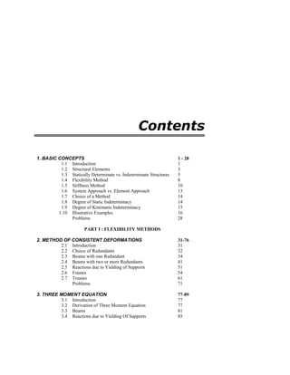
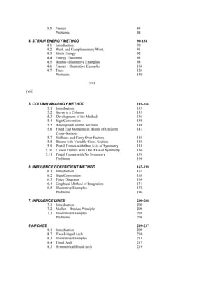
The Pushover Analysis from basics - Rahul LeslieRahul Leslie
Pushover analysis has been in the academic-research arena for quite long. The papers published in this field usually deals mostly with proposed improvements to the approach, expecting the reader to know the basics of the topic... while the common structural design practitioner, not knowing the basics, is left out from participating in those discussions. Here I’m making an effort to bridge that gap by explaining the Pushover analysis, from basics, in its simplicity.
A write up on this topic can be found at http://rahulleslie.blogspot.in/p/blog-page.html, though does not cover the full spectrum presented in this slide show.
Earthquake Load Calculation (base shear method)
The 3-story standard office building is located in Los Angeles situated on stiff soil. The
structure of the building is steel special moment frame. All moment-resisting frames are
located at the perimeter of the building. Determine the earthquake force on each story in
North-South direction.
Design and Detailing of RC Deep beams as per IS 456-2000VVIETCIVIL
Visit : https://teacherinneed.wordpress.com/
1. DEEP BEAM DEFINITION - IS 456
2. DEEP BEAM APPLICATION
3. DEEP BEAM TYPES
4. BEHAVIOUR OF DEEP BEAMS
5. LEVER ARM
6. COMPRESSIVE FORCE PATH CONCEPT
7. ARCH AND TIE ACTION
8. DEEP BEAM BEHAVIOUR AT ULTIMATE LIMIT STATE
9. REBAR DETAILING
10. EXAMPLE 1 – SIMPLY SUPPORTED DEEP BEAM
11. EXAMPLE 2 – SIMPLY SUPPORTED DEEP BEAM; M20, FE415
12. EXAMPLE 3: FIXED ENDS AND CONTINUOUS DEEP BEAM
13. EXAMPLE 4 : FIXED ENDS AND CONTINUOUS DEEP BEAM
American Society of Civil Engineers
Minimum Design Loads for Buildings and Other Structures
2010
--------------------------
Te invito a que visites mis sitios en internet:
_*Canal en youtube de ingenieria civil_*
https://www.youtube.com/@IngenieriaEstructural7
_*Blog de ingenieria civil*_
https://thejamez-one.blogspot.com
Seismic analysis of multi storey reinforced concrete buildings frame”ankialok
The opinion that designing new buildings to be Earthquake resistant will cause substantial additional costs is still among the constructional professionals. In a country of moderate seismicity adequate seismic resistance of new buildings may be achieved at no or no significant additional cost however the expenditure needed to ensure adequate seismic resistance may depend strongly on the approach selected during the conceptual design phase and the relevant design method. Regarding the conceptual design phase early collaboration between the architect and civil engineering is crucial.
Dhruvin Goyani
M.Tech Structural
This PPT is For All the Civil Engineering Students and Specially for M.tech Students Who Trying To Learn Something New on Earthquake and its Resisting Methods and also For Seismic Analysis
FINITE ELEMENT ANALYSIS OF A PRESTRESSED CONCRETE BEAM USING FRP TENDONGirish Singh
Concrete prestressed structural components exist in buildings and bridges in different forms. Understanding the response of these components during loading is crucial to the development of an overall efficient and safe structure. Different methods have been utilized to study the response of structural components. Experimental based testing has been widely used as a means to analyse individual elements and the effects of concrete strength under loading.
While this is a method that produces real life response, it is extremely time consuming, and the use of materials can be quite costly. In this paper we used finite element analysis to study behaviour of these components. The use of computer software (Ansys) to model these elements is much faster, and extremely cost- effective. To fully understand the capabilities of finite element computer software (Ansys), we look back to experimental data and simple analysis.
Data obtained from a finite element analysis package is not useful unless the necessary steps are taken to understand what is happening within the model that is created using the software. Also, executing the necessary checks along the way, is key to make sure that what is being output by the Ansys is valid.
This paper is a study of prestressed concrete beams using finite element
analysis to understand the response of prestressed concrete beams due to transverse loading and to analyse the behaviour of FRP material under these circumstances.
This paper also includes the comparison of steel and FRP on the same module and also gives the final load v/s deflection curve under the both linear and non-linear properties of the materials.
Now in its seventh edition, Basic Engineering Mathematics is an established textbook that has helped thousands of students to succeed in their exams. Mathematical theories are explained in a straightforward manner, being supported by practical engineering examples and applications in order to ensure that readers can relate theory to practice. The extensive and thorough topic coverage makes this an ideal text for introductory level engineering courses. This title is supported by a companion website with resources for both students and lecturers, including lists of essential formulae, multiple choice tests, and full solutions for all 1,600 further questions.
2. Advanced Structural
Analysis
with Finite Element Method
Ashok K. Jain
Professor of Civil Engineering
Indian Institute of Technology Roorkee
ROORKEE
and
Former Director
Malaviya National Institute of Technology
JAIPUR
Third Edition 2015
Nem Chand & Bros, Roorkee, 247667, U.K.,
India
170 Solved
Examples
3. Contents
1. BASIC CONCEPTS 1 - 28
1.1 Introduction 1
1.2 Structural Elements 3
1.3 Statically Determinate vs. Indeterminate Structures 5
1.4 Flexibility Method 8
1.5 Stiffness Method 10
1.6 System Approach vs. Element Approach 13
1.7 Choice of a Method 14
1.8 Degree of Static Indeterminacy 14
1.9 Degree of Kinematic Indeterminacy 15
1.10 Illustrative Examples 16
Problems 28
PART I : FLEXIBILITY METHODS
2. METHOD OF CONSISTENT DEFORMATIONS 31-76
2.1 Introduction 31
2.2 Choice of Redundants 32
2.3 Beams with one Redundant 34
2.4 Beams with two or more Redundants 41
2.5 Reactions due to Yielding of Supports 51
2.6 Frames 54
2.7 Trusses 61
Problems 71
3. THREE MOMENT EQUATION 77-89
3.1 Introduction 77
3.2 Derivation of Three Moment Equation 77
3.3 Beams 81
3.4 Reactions due to Yielding Of Supports 85
4. 3.5 Frames 85
Problems 88
4. STRAIN ENERGY METHOD 90-134
4.1 Introduction 90
4.2 Work and Complementary Work 91
4.3 Strain Energy 92
4.4 Energy Theorems 95
4.5 Beams - Illustrative Examples 98
4.6 Frames - Illustrative Examples 103
4.7 Truss 126
Problems 130
(vii)
(viii)
5. COLUMN ANALOGY METHOD 135-166
5.1 Introduction 135
5.2 Stress in a Column 135
5.3 Development of the Method 136
5.4 Sign Convention 139
5.5 Analogous Column Sections 139
5.6 Fixed End Moments in Beams of Uniform
Cross-Section
141
5.7 Stiffness and Carry Over Factors 145
5.8 Beams with Variable Cross-Section 148
5.9 Portal Frames with One Axis of Symmetry 153
5.10 Closed Frames with One Axis of Symmetry 156
5.11 Portal Frames with No Symmetry 159
Problems 164
6. INFLUENCE COEFFICIENT METHOD 167-199
6.1 Introduction 167
6.2 Sign Convention 168
6.3 Force Diagrams 169
6.4 Graphical Method of Integration 171
6.5 Illustrative Examples 172
Problems 196
7. INFLUENCE LINES 200-208
7.1 Introduction 200
7.2 Muller – Breslau Principle 200
7.3 Illustrative Examples 203
Problems 208
8 ARCHES 209-237
8.1 Introduction 209
8.2 Two-Hinged Arch 210
8.3 Illustrative Examples 213
8.4 Fixed Arch 217
8.5 Symmetrical Fixed Arch 219
5. 8.6 Elastic Centre 222
8.7 Illustrative Examples 223
8.8 Influence Lines for a Hinged Arch 232
8.9 Influence Lines for a Fixed Arch 234
Problems 235
PART 2 STIFFNESS METHODS
9. SLOPE-DEFLECTION METHOD 241-300
9.1 Introduction 241
9.2 Development of Slope-Deflection Equations 241
9.3 Equations of Equilibrium 243
9.4 Beams 244
9.5 Frames: No Side Sway 250
(ix)
9.6 Frames: with Side Sway 254
9.7 Frames with Sloping Legs 271
9.8 Effect of Change in Temperature 285
9.9 Flexibility and Stiffness Matrices 289
Problems 296
10. MOMENT DISTRIBUTION METHOD 301-351
10.1 Development of the Method 301
10.2 Distribution Factors 303
10.3 Sign Convention 304
10.4 Beams and Frames with no Side Sway 304
10.5 Beams with Uneven Support Settlement 318
10.6 Frames with Side Sway 321
10.7 Frames with Uneven Support Settlements 328
10.8 Symmetry and Anti-Symmetry 330
10.9 Comments on the Moment Distribution Method 348
Problems 348
11. DIRECT STIFFNESS METHOD – 2D ELEMENTS 352-432
11.1 Development of Stiffness Matrices 352
11.2 Properties of Stiffness Matrices 358
11.3 Transformation of Coordinates 360
11.4 Element Load Vector 363
11.5 Assembly of Global Matrices 364
11.6 Illustrative Examples 373
11.7 Boundary Conditions 383
11.8 Support Reactions 387
11.9 Inclined Roller Support 387
11.10 Summary of Direct Stiffness Method 387
11.11 Beams on Elastic Foundation 389
11.12 Illustrative Examples 390
11.13 Comparison of Flexibility and Stiffness Methods 427
Problems 428
12. DIRECT STIFFNESS METHOD – 3D ELEMENTS 433-461
12.1 Stiffness Matrix- Bar Element 433
12.2 Stiffness Matrix- Beam Element 434
6. 12.3 Stiffness Matrix- Grid Element 436
12.4 Stiffness Matrix-Shear Wall element 437
12.5 Stiffness Matrix- Beam with Rigid Ends – 2D 439
12.6 Stepped Members 441
12.7 Transformation Matrix – 3D Bar Element 447
12.8 Transformation Matrix – 3D Beam Element 451
12.9 Constraints and Link Elements 457
12.10 Modeling Bearings and Expansion Joints in Bridges 460
References 461
Problem 461
(x)
13. FINITE ELEMENT METHOD 462-532
13.1 Introduction 462
13.2 Modeling, Discretization and Errors 464
13.3 Steps in Finite Element Method 464
13.4 Interpolation and Shape Functions 465
13.5 Degree of Continuity 466
13.6 Bar Element 466
13.7 Beam Element 468
13.8 Linear Triangle or Constant Strain Triangle 469
13.9 Bi–Linear Rectangle – Q4 473
13.10 Quadratic Rectangle Q8 And Q9 475
13.11 Normalized Coordinates 475
13.12 Rectangular Elements – Lagrange family 476
13.13 Illustrative Examples 478
13.14 Rectangular Elements Serendipity Family 481
13.15 Sequence of Node Numbering 483
13.16 Curved and Isoparametric Elements 484
13.17 Convergence Criteria 485
13.18 Stress-Strain Relations 485
13.19 StrainDisplacement Relations 490
13.20 Equilibrium Equations 492
13.21 Compatibility 492
13.22 Virtual Work 493
13.23 Element Stiffness Matrix – Isoparametric Elements 494
13.24 Transformation of Coordinates 499
13.25 Numerical Integration – Gauss Quadrature 499
13.26 Illustrative Examples 501
13.27 Equivalent Nodal Loads 508
13.28 Consistent Mass Matrix 513
13.29 Illustrative Examples 514
13.30 Application to Field Problems 519
References 529
Problems 529
14. NONLINEAR ANALYSIS: Material Nonlinearity 533-575
14.1 Introduction 533
14.2 Stress-Strain Curve of Steel 533
7. 14.3 Theory of Plastic Analysis 534
14.4 Plastic Hinge and Mechanism 537
14.5 Moment-Curvature Relation 539
14.6 Plastic Analysis 540
14.7 Illustrative Examples 542
14.8 Hysteresis Loops 558
14.9 Assumptions 560
14.10 Member Stiffness Matrix 560
14.11 Nonlinear Stiffness Matrix Analysis 562
14.11.1 Incremental Displacement and Load Vectors 566
14.11.2 Modification of the Structural Stiffness
Matrix
566
(xi)
14.11.3 Unbalanced Load Vector 567
14.12 Ductility 569
14.13 Illustrative Examples 570
References 574
Problems 574
15. NONLINEAR ANALYSIS : Geometric Nonlinearity 576-594
15.1 Introduction 576
15.2 Geometric Stiffness Matrix - Bar Element 577
15.3 Cable Suspension Systems 579
15.4 P-Delta Effects in Structures 580
15.5 Geometric Stiffness Matrix – Beam Element 581
15.6 Nonlinear Solution Algorithms 584
15.7 Convergence Criteria 587
15.8 Illustrative Examples 588
Reference 593
Problems 593
APPENDIX A – MATRIX ALGEBRA AND MATLAB 595-614
APPENDIX B – SLOPES AND DEFLECTIONS 615-616
APPENDIX C - FIXED END MOMENTS 617-618
INDEX 619-621