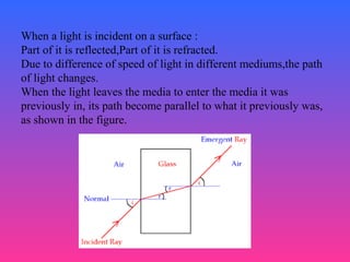
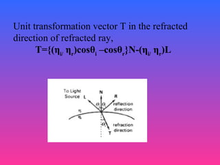
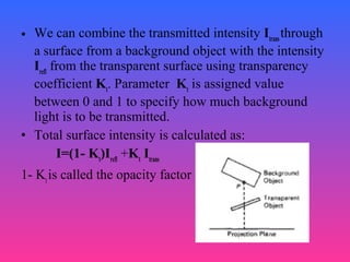
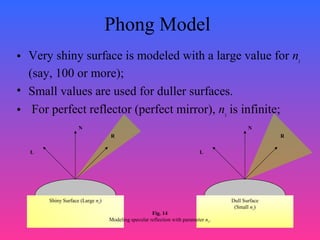
2. 2
Specular Reflection
• Specular reflection is the result of total, or near
total reflection of the incident light in a
concentrated region around the specular-reflection
angle.
• Shiny surfaces have a narrow specular-reflection
range.
• Dull surfaces have a wider reflection range.
3. 3
Specular Reflection
Figure 13 shows the specular reflection
direction at a point on the
illuminated surface. In this figure,
• R represents the unit vector in
the direction of specular reflection;
• L – unit vector directed toward the
point light source;
• V – unit vector pointing to the viewer from the surface
position;
• Angle Φ is the viewing angle relative to the specular-
reflection direction R.
Fig. 13
Modeling specular reflection.
N
L
To Light Source
θ θ
R
VΦ
4. 4
Phong Model
Phong model is an empirical model for calculating the
specular-reflection range:
• Sets the intensity of specular reflection proportional to
cosns
Φ;
• Angle Φ assigned values in the range 0o
to 90o
, so that
cosΦ values from 0 to 1;
• Specular-reflection parameter ns
is determined by the
type of surface,
• Specular-reflection coefficient ks
equal to some value
in the range 0 to 1 for each surface.
5. 5
Phong Model
• Very shiny surface is modeled with a large value for ns
(say, 100 or more);
• Small values are used for duller surfaces.
• For perfect reflector (perfect mirror), ns
is infinite;
N
L
R
Shiny Surface (Large ns)
N
L
R
Dull Surface
(Small ns)
Fig. 14
Modeling specular reflection with parameter ns.
7. 7
Specular reflection coefficient(W(0))
It gives the model monochromatic specular intensity variations ,
over the range 0< 0< 90 . W(0) increases as angle of incidence
increases .
Phong specular –reflection model
I = W(0) I cos ospec L
ns
Where I is the intensity of the light source and o is the
viewing angle relative to the specular reflection direction R.
L
9. 9
Phong Model
Phong specular-reflection model:
Ispec
= ks
Il
cosns
Φ
Since V and R are unit
vectors in the viewing
and specular-reflection
directions, we can
calculate the value of
cosns
Φ with the dot
product V.
R.
Ispec
= ks
Il
(V.
R)ns
Fig. 13
Modeling specular reflection.
N
L
To Light Source
θ θ
R
VΦ
10. 10
Phong Model
R + L = (2N.
L)N
R = (2N.
L)N-L
N
L
R
N.
L
L
Fig. 16
Calculation of vector R by considering projections onto the direction of the normal vector N.
13. 13
Specular reflections from a spherical surface for varying
specular parameter values and a single light source.
14. 14
Combine Diffuse & Specular
Reflections
For a single point light source, we can model
the combined diffuse and specular reflections
from a point on an illuminated surface as
I = Idiff
+ Ispec
I = ka
Ia
+ kd
Il
(N.
L) + ks
Il
(N.
H)ns
15. 15
Combine Diffuse & Specular
Reflections with Multiple Light
Sources
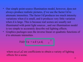
If we place more than one point source in a
scene, we obtain the light reflection at any
surface point by summing the contributions
from the individual sources:
I = ka
Ia
+ Σn
i=1
Ili
[kd
(N.
Li
) + ks
(N.
Hi
)ns
]
20. 20
Warn Model
• The warn model provides a method for simulating studio
lighting effects by controlling light intensity in different
directions.
• Light sources are modelled as point on a reflecting surface,
using Phong model for the surface points . Then the intensity in
different directions is controlled by selecting values for the
Phong exponent.
In addition, light controls and spotlighting, can be simulated in
the warn model . Flaps are used to control the amount of light
emitted by a source in various directions . Two flaps are
provided for each of the x,y and z directions .
Spotlights are used to control the amount of light emitted
within a cone with apex at a point source position.
22. 22
• As radiant energy from a point light source travels through space,
its amplitude is attenuated by the factor l/d, where d is the
distance that the light has traveled. ie. surface close to the light
source (small d) receives a higher incident intensity from the
source than a distant surface (large d).
• To produce realistic lighting effects, our illumination model
should take this intensity attenuation into account. Otherwise, we
are illuminating all surfaces with the same intensity, no matter
how far they might be from the light source. If two parallel
surfaces with the same optical parameters overlap, they would be
indistinguishable from each other. The two surfaces would be
displayed as one surface.
2
Intensity Attenuation
24. 24
• Our simple point-source illumination model, however, does not
always produce realistic pictures, if we use the factor l/d to
attenuate intensities. The factor l/d produces too much intensity
variations when d is small, and it produces very little variation
when d is large. This is because real scenes are usually not
illuminated with point light sources , and our illumination model
is too simple to accurately describe red lighting effects.
• Graphics packages uses the inverse linear or quadratic functions of
d to attenuate intensities.
F(d)=1/a + a d + a d
2
2
o 1 2
2
where ao,a1,a2 are coefficients to obtain a variety of lighting
effects for a scene.
25. 25
• With a given set of attenuation coefficients , the magnitude of the
attenuation function can be limit to 1, as
F(d)=min(1,1/a + a d + a d )o 1 2
2
• Using this function , basis illumination model can be written
as:-
I = ka
Ia
+ Σn
i=1
f(d )Ili
[kd
(N.
Li
) + ks
(N.
Hi
)ns
]i
Where di is the distance , light has travelled from a light
source i.
26. Color considerations
The basic illumination model considers only
the monochromatic lighting effects. To
incorporate these, intensity equation is to be
written as a function of the color properties of
light sources and object surfaces.
27. STEPS
• For an RGB description, each color in a
scene is expressed in terms of red green
blue components .
• We then specify the RGB components of
light source intensity and surface colors,
and illumination model calculates the RGB
component of the reflected light.
29. 1.
• To set surface colors ,specify the reflectivity
coefficients vectors, for eg., diffuse reflection
would have k(dr),k(dg),k(db) components.
• For a blue surface,the intensity equation is :
• I = kab
Iab
+ Σn
i=1
f(d )Ilbi
[kdb
(N.
Li
) + ksb
(N.
Hi
)ns
]
• Here,k(dr)=k(dg)=0 ; k(db) has value in range 0 to
1.
30. 2.
• Another method for setting surface color is to specify the
components of diffuse and specular color vectors for each
surface ,without changes in reflectivity coefficients.
• For an RGB color representation the components of these two
surfaces color vector can be denoted as ( Sdr,
Sdg
,Sdb
) and (SSr
SSg
SSb
).the blue light component of reflected light is calculated as
:
• I = ka
Sdb
Iab
+ Σn
i=1
f(d )Ilbi
[kd
Sdb
(N.
Li
) + ks
SSb
(N.
Hi
)ns
]
• This approach is more flexible,since color parameters can be
set independently from reflectivity values.
31. • We can simply represent any component of a color
specification with its spectral wavelength lambda
”λ”.
• Then,
• I = ka
Sdλ
Iaλ
+ Σn
i=1
f(d )Ilλi
[kd
Sdλ
(N.
Li
) + ks
SSλ
(N.
Hi
)ns
]
**spectral wavelength is the different wavelength
assigned to the various colours in the spectrum.**
32. TRANSPERENCY
A transparent surfaces produces both reflected and
transmitted light. The relative contribution of the
transmitted light depends on the degree of
transparency of the surface and whether any light
sources or illuminated surfaces are behind the
transparent surfaces.
Both diffuse and specular transmissions can take
place at the surfaces of transparent object.
Diffuse reflections are helpful when a blurred
image of background surface is to be obtained.
33.
34. When a light is incident on a surface :
Part of it is reflected,Part of it is refracted.
Due to difference of speed of light in different mediums,the path
of light changes.
When the light leaves the media to enter the media it was
previously in, its path become parallel to what it previously was,
as shown in the figure.
35. Snells’ law :
Angle of refraction θi
,the index of refraction ηi
of incident
material , the index of refraction ηi
of refracting material
then,
Sineθr
=(ηi/
ηr
)sinθi
36. Index of refraction of a material is a function of the
wavelength of the incident light,so that the different
components of a light ray will be refracted at
different angles.
We can use average refractive index for the
different materials modelled In a scene.
The refractive index of air is approximately one,and
crown glass is 1.5.
Since trignometric functions arent always feasible to
find out,refraction is modelled by simply shifting
the path of incident light a small amount.
37. TRANSFORMATION VECTOR
Transformation vector can be used to locate
intersections of the refraction path with
objects behind the transparent surface.
To produce realistic display, this
determination is very necessary, and also
require considerable computation.
If N is the unit surface normal,
L is the unit vector in the direction of light
source,
38. Unit transformation vector T in the refracted
direction of refracted ray,
T={(ηi/
ηr
)cosθi
–cosθr
}N-(ηi/
ηr
)L
39. A new approach involves ignoring the path shift
altogether, to avoid cumbersome operations.
• This is helpful for thin surfaces.
• This is a speed-up process, but might pose
problems when thin multilayer surfaces are
involved.
40. • We can combine the transmitted intensity Itrans
through
a surface from a background object with the intensity
Irefl
from the transparent surface using transparency
coefficient Kt
. Parameter Kt
is assigned value
between 0 and 1 to specify how much background
light is to be transmitted.
• Total surface intensity is calculated as:
I=(1- Kt
)Irefl
+Kt
Itrans
1- Kt
is called the opacity factor
41. Shadows
• Shadows areas are those surfaces areas or
sections that cannot be seen from the light
source.
• Shadows can be treated as surface patterns
and stored in pattern arrays.
42. • Shadows patterns generated by hidden surface
methods are valid for any selected viewing
positions as long as the light source positions
are not changed.
• Surface that are visible from view position are
shaded according to lighting pattern for that
particular view, combined with texture
patterns in that view if any.
• Shadow areas can be displayed only with
ambient light intensity.
43. OPACITY FACTOR
• Values from 0 to 1.
• Opacity high : near 1,transmit very little
from background images.
• Opacity low : near 0,transmit a lot more
from background images.
44. • Transparent effects are often implemented with the z-
buffer algorithms.
*process opaque objects first to determine depths
for the visible opaque surface.
*then, depth position of transparent objects are
compared to values previously stored in depth buffer.
*then, reflective individual intensity of the
individual surface(stored in frame buffer),combined
with intensity change due to transparent surface is
calculated, and new intensity determined.
*additional storage for parameters of transparent
surface(like depths) can be used for accuracy and
speed.
very shiny surface is modeled with a large value for ns (say, 100 or more), and small values are used for duller surfaces. For perfect reflector (perfect mirror), ns is infinite;