Downloaded 23 times

![Illumination Terminology Radiant power [flux] ( Φ ) Rate at which light energy is transmitted (in Watts). Radiant Intensity (I) Power radiated onto a unit solid angle in direction( in Watt/sr) e.g.: energy distribution of a light source (inverse square law) Radiance (L) Radiant intensity per unit projected surface area( in Watts/m 2 sr) e.g.: light carried by a single ray (no inverse square law) Irradianc (E) Incident flux density on a locally planar area (in Watts/m 2 ) Radiosity (B) Exitant flux density from a locally planar area ( in Watts/m 2 )](https://image.slidesharecdn.com/10illumination-101012143442-phpapp02/85/10illumination-43-320.jpg)

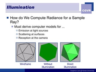
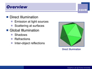
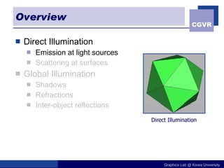
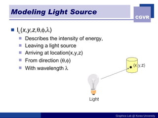
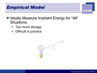
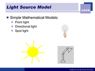
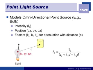
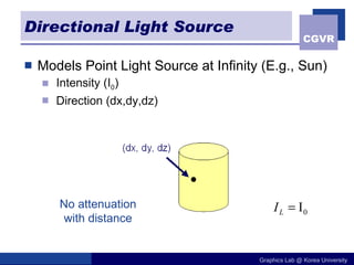
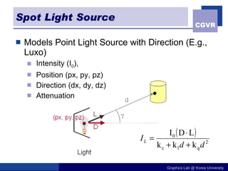
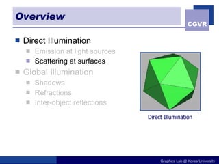
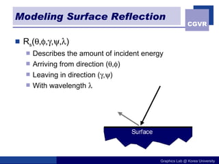
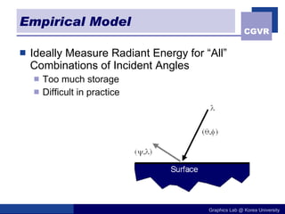
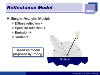
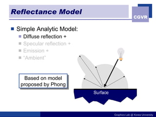
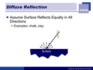
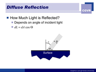
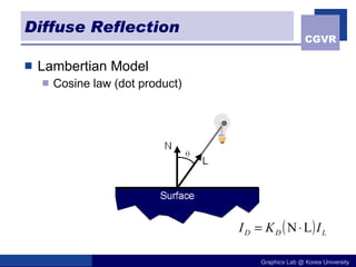
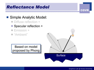
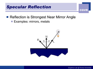
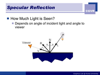
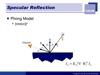
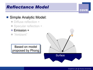
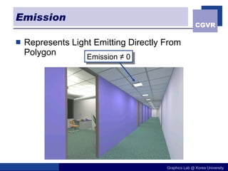
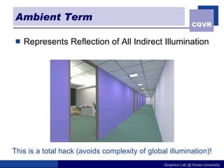
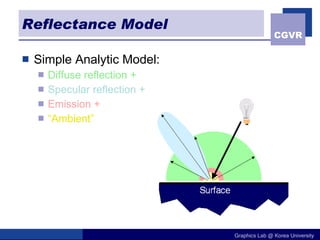
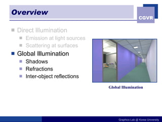
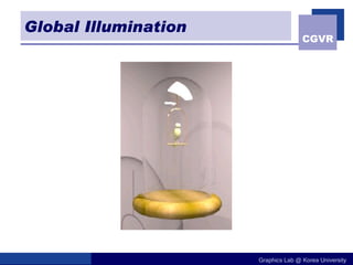
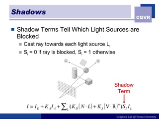
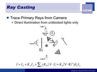
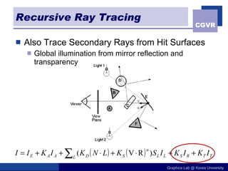
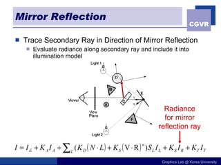
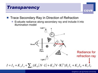
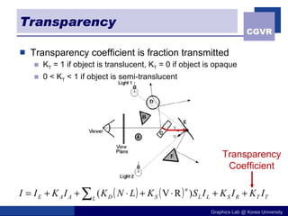
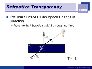
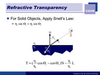
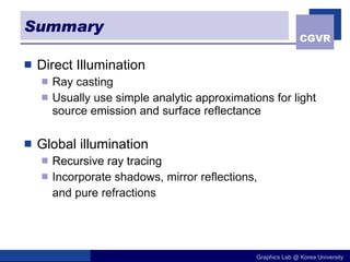
The document discusses illumination models in computer graphics. It covers direct illumination from light sources and scattering at surfaces. It also discusses global illumination techniques like shadows, reflections and refractions using ray tracing. Common lighting models include point lights, directional lights and spot lights for light sources, and Lambertian and Phong reflection models for surfaces. Global illumination methods recursively trace rays to account for effects of indirect lighting. Key terms discussed include radiant power, radiant intensity, radiance, irradiance and radiosity.