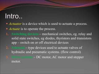
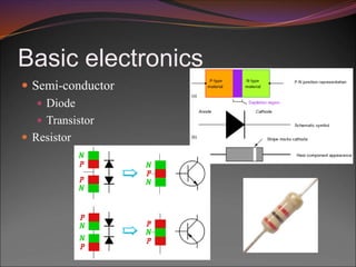
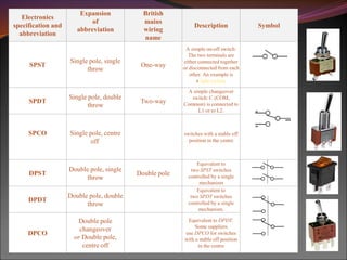
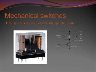
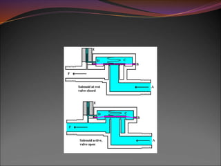
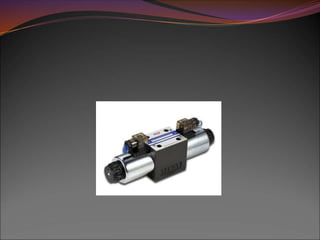
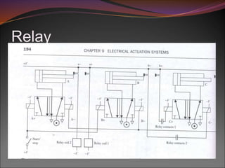
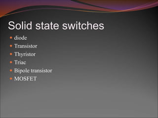
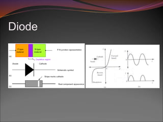
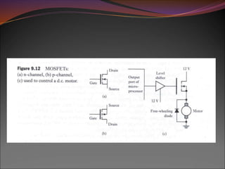
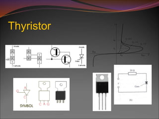
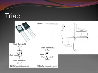
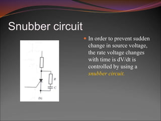
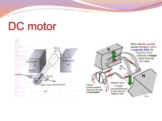
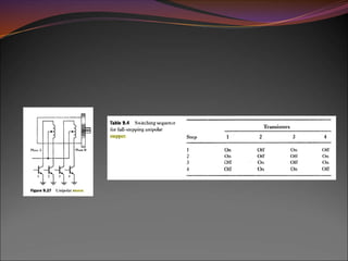
By
Dr. Anurag Dixit
Intro..
 Actuator is a device which is used to actuate a process.
 Actuate is to operate the process.
1. Switching devices – mechanical switches, eg. relay and
solid state switches, eg diodes, thyristors and transistors
app – switch on or off electrical devices
2. Solenoid – type devices used to actuate valves of
hydraulic and pneumatic systems. (flow control)
3. Drive systems – DC motor, AC motor and stepper
motor.
Basic electronics
 Semi-conductor
 Diode
 Transistor
 Resistor
Mechanical switches
Electronics
specification and
abbreviation
Expansion
of
abbreviation
British
mains
wiring
name
Description Symbol
SPST
Single pole, single
throw
One-way
A simple on-off switch:
The two terminals are
either connected together
or disconnected from each
other. An example is
a light switch.
SPDT
Single pole, double
throw
Two-way
A simple changeover
switch: C (COM,
Common) is connected to
L1 or to L2.
SPCO Single pole, centre
off
switches with a stable off
position in the centre
DPST
Double pole, single
throw
Double pole
Equivalent to
two SPST switches
controlled by a single
mechanism
DPDT
Double pole, double
throw
Equivalent to
two SPDT switches
controlled by a single
mechanism.
DPCO
Double pole
changeover
or Double pole,
centre off
Equivalent to DPDT.
Some suppliers
use DPCO for switches
with a stable off position
in the centre
Mechanical switches
 Relay - A relay is an electrically operated switch.
Relay
 Electrically operated switches in which changing the
current in one circuit switches a current on or off in
another circuit.
 NO – normally open , NC – normally closed
 Output from controller is small so it is often used with
transistor.
 Relays are inductances
 Free – wheeling or fly back diode.
 Importance
 To operate a device which needs larger current.
solenoid
 Solenoid is an electromagnet which can be used as an
actuator.
 Electrically operated actuators.
 Solenoid valves are used in hydraulic and pneumatic
systems.
Relay
Solid state switches
 diode
 Transistor
 Thyristor
 Triac
 Bipole transistor
 MOSFET
Diode
Bipolar Transistors
Transistors are manufactured
in different shapes but they
have three leads (legs).
The BASE - which is the lead
responsible for activating the
transistor.
The COLLECTOR - which is
the positive lead.
The EMITTER - which is the
negative lead.
Transistor as a switch
 Bipolar switch
Darlington pair
 Transistor needs large base current to switch on.
 Output from microprocessor has a small input.
 A second transistor is employed to enable a high current
to be switched on. Such a combination of pair of transistor
is called Darlington pair.
MOSFET
 Metal oxide field effect transistor
 Two types
 N channel
 P channel
 Three terminals
 Gate (G)
 Drain (D)
 Source (S)
Operation
 When MOSFET is turned on current flows from source to
drain .
 Voltage is applied between gate-source to turn on
MOSFET.
 MOSFET can be turned off by removing gate voltage.
 Gate has full control over the control of MOSFET.
 A level shifter buffer required to raise the voltage level at
which the MOSFET starts to activate.
 Interfacing with µp is simpler then transistor.
Thyristor
 Thyristors have three states:
 Reverse blocking mode — Voltage is applied in the
direction that would be blocked by a diode
 Forward blocking mode — Voltage is applied in the
direction that would cause a diode to conduct, but the
thyristor has not yet been triggered into conduction
 Forward conducting mode — The thyristor has been
triggered into conduction and will remain conducting until
the forward current drops below a threshold value known
as the "holding current"
Triac
Voltage control
Thyristor dc control
Lamp dimmer
 Thyristor dimmers switch on at an adjustable time (phase
angle) after the start of each alternating current half-cycle,
thereby altering the voltage waveform applied to lamps
and so changing its RMS effective value.
 R1 is a current limiting resistor and R2 is a potentiometer.
 By adjusting R2 thyristor can be made to trigger at any
point between 0 deg and 90 deg.
Snubber circuit
 In order to prevent sudden
change in source voltage,
the rate voltage changes
with time is dV/dt is
controlled by using a
snubber circuit.
Drive systems
 DC motor
 AC motor
 Stepper motor
DC motor
Working principle
 When current passes through the coil, the resulting forces
acting on its sides at right angles to the field cause forces
to act on those sides to give a rotation.
 For the rotation to continue, when the coil passes through
the vertical position the current direction through the coil
has to be reversed.
Parts
 Stator (permanent or non permanent magnet)
 Rotor (electromagnet)
 Armature
 Commutator
 Brush
 A brush type dc motor is essentially a coil of wire which is
free to rotate - termed as rotor in the field of permanent or
non-permanent magnet.
 The magnet termed a stator since it is stationery.
 For the rotation to continue, when coil passes through
vertical position the current direction is reversed which is
got by use of brushes making contact with split ring
commutator.
 For an armature conductor of length l and carrying a
current I, the force resulting from a magnetic flux of
density B at right angles to the conductor is given by
F = BIL
 Torque produced along the axis of the conductor due to
force F is
T = F x b
= nBIL x b
= KI
 Since armature is a rotating magnetic field it will have
back emf Vb. The back emf depends on rate of flux
induced in coil. Back emf is proportional to angular
velocity w
Vb = Kw
 Equivalent circuit diagram for D.C motor
V
a Vb
Ra
La = inductance
 Neglecting the inductance produced due to armature coil,
then effective voltage producing current I through
resistance R is Va-Vb, hence
 I = (Va - Vb)/R = (Va – Kw)/R
T = K I
= k(Va – Kw)/R
Control of brush type DC motor
 Speed control can be obtained by controlling the voltage
applied to the armature. Since fixed voltage supply is
often used, a variable voltage is obtained by an electronic
circuit.
 When A.C supply is used a Thyristor can be used to
control the average voltage applied to armature.
 PWM – pulse width modulation
 Control of d.c motors by means of control signal from
microprocessors.
Brush type motor with non-
permanent magnet
 Series wound
 Shunt wound
 Compound wound
 Separately excited
Series wound
 Armature and field
windings are connected in
series.
 Highest starting torque
 Greatest no load speed
 Reversing the polarity of
supply will not effect the
direction of rotation of
rotor.
Shunt wound
 Armature and field coils
are in parallel.
 Lowest starting torque
 Good speed regulation.
 Almost constant speed
regardless of load.
 For reversing direction of
rotation either armature
coil or field coil supply
has to be reversed.
Compound wound
 Two field windings one in
series an another in
parallel with armature
windings.
 High starting torque with
good speed regulation.
Separately excited
 Separate control of
armature and field coils.
 Speed of these motors can
be controlled by separately
varying the armature or
field current.
Brush less dc motor
 Its consists of a sequence of stator coils and a permanent
magnet rotor.
 Current carrying conductors are fixed and magnet moves.
 Rotor is ferrite or permanent magnet.
 The current to the stator coils are electronically switched
by transistor in sequence round the coils.
 Switching being controlled by position of rotors.
 Hall effect sensors are used to input signals related to a
particular position of rotor.
A.C motors
 Single phase squirrel cage induction motor
 Its consists of a squirrel cage rotor, this being copper or
aluminum bars that fit into slots in end rings to form a
complete circuit.
 Its consists of a stator having set of windings.
 Alternating current is passed through stator windings an
alternating magnetic field is produced.
 As a result EMF are induced in conductors in the magnetic
field.
 Initially when rotor is stationery net torque is zero.
 Motor is not self starting.
3-phase induction motor
 3 windings located 120 deg
apart each winding being
connected to one of the three
lines of the supply.
 3 phase reach maximum
currents at different times,
magnetic field rotates round
the stator poles completing
one rotation is one full cycle.
 Self starting
Synchronous motors
 Similar to that of induction
motor but rotor will be a
permanent magnet.
 Magnets rotate with the
same frequency as that of
rotating magnetic field
which rotates 360 deg in
one cycle of supply.
 Used when precise speed
is required.
 Not self starting.
Speed control of AC motor
 Speed control of A.C motor
is done by provision of
variable frequency supply.
 Torque is constant when
ratio of applied stator
voltage to frequency ration is
constant.
 AC is rectified to DC by
convertor and inverted back
to AC with a selected
frequency.
Stepper motors
 Stepper motor is a device that produce rotation though
equal angles called as steps, for each digital pulse supplied
to its input.
Stepper motors
Variable reluctance motor
 Rotor is made of soft steel and
is cylindrical with four poles,
fewer poles than on the stator.
 When opposite pair of
windings has current switched
to them, a magnetic field is
produced with line of force
pass from stator to nearest
poles of rotor.
 Rotor will until it is in
minimum reluctance position.
 Step angle 7.5 deg to 15 deg.
Permanent magnet stepper
 Two phase four poles.
 Coils on opposite pairs of poles
are in series.
 Current is supplied from dc
source.
 Rotor is a permanent magnet.
 Rotor rotates in 45 deg steps.
 Step angles 1.8, 7.5, 15, 30, 34,
or 90 deg available.
Hybrid stepper motor
 Combined features of both
variable reluctance and permanent
magnet motors.
 Permanent magnets are encased in
iron caps which are cut to have
teeth.
 It motor has n phase and m teeth
on the rotor, the total number of
steps per revolution will be nm
 0.9 and 0.8 deg steps available.
 High accuracy positioning
applications.
Specifications
 Phase
 Number of independent
windings on the stator, eg a
three phase motor.
 Step angle
 Angle through which the rotor
rotates from one switching
change for the stator.
 Holding torque
 Maximum torque that can
applied to a powered motor
without moving it from its rest
position and causing spindle
rotation.
 Pull – in torque
 This is the maximum torque
against which a motor will
start for a given pulse rate
and reach synchronism
without losing a step.
 Pull – out torque
 Maximum torque against
that can be applied to a
motor, running at a given
stepping rate, without
loosing synchronism.
 Pull – in rate
 Maximum switching rate at
which a loaded motor can start
without loosing a step.
 Pull – out rate
 Switching rate at which a
loaded motor will remain in
synchronism as the switching
rate is reduced.
 Slew range
 Range of switching rates
between pull-in and pull-out
within the motor runs in
synchronism but cannot start
up or reverse.
Bipolar stepper Unipolar stepper
H bridge
Stepper motor control
 Two phase motors are termed as bipolar motors when they have 4
connecting wires for signals.
 Solid state switches can be used to switch dc supply between the pair of
stator windings.
Bipolar stepper
Merits and demerits
Merits
 A high accuracy of motion is possible, even under open-loop control.
 Large savings in sensor (measurement system) and controller costs
are possible when the open-loop mode is used.
 Because of the incremental nature of command and motion, stepper
motors are easily adaptable to digital control applications.
 No serious stability problems exist, even under open-loop control.
 Torque capacity and power requirements can be optimized and the
response can be controlled by electronic switching.
 Brushless construction has obvious advantages.
Demerits
 They have low torque capacity (typically less than 2,000
oz-in) compared to DC motors.
 They have limited speed (limited by torque capacity and
by pulse-missing problems due to faulty switching
systems and drive circuits).
 They have high vibration levels due to stepwise motion.
 Large errors and oscillations can result when a pulse is
missed under open-loop control.
electrical-actuation-systems.ppt

electrical-actuation-systems.ppt

  • 1.
  • 2.
    Intro..  Actuator isa device which is used to actuate a process.  Actuate is to operate the process. 1. Switching devices – mechanical switches, eg. relay and solid state switches, eg diodes, thyristors and transistors app – switch on or off electrical devices 2. Solenoid – type devices used to actuate valves of hydraulic and pneumatic systems. (flow control) 3. Drive systems – DC motor, AC motor and stepper motor.
  • 3.
    Basic electronics  Semi-conductor Diode  Transistor  Resistor
  • 4.
    Mechanical switches Electronics specification and abbreviation Expansion of abbreviation British mains wiring name DescriptionSymbol SPST Single pole, single throw One-way A simple on-off switch: The two terminals are either connected together or disconnected from each other. An example is a light switch. SPDT Single pole, double throw Two-way A simple changeover switch: C (COM, Common) is connected to L1 or to L2. SPCO Single pole, centre off switches with a stable off position in the centre DPST Double pole, single throw Double pole Equivalent to two SPST switches controlled by a single mechanism DPDT Double pole, double throw Equivalent to two SPDT switches controlled by a single mechanism. DPCO Double pole changeover or Double pole, centre off Equivalent to DPDT. Some suppliers use DPCO for switches with a stable off position in the centre
  • 5.
    Mechanical switches  Relay- A relay is an electrically operated switch.
  • 6.
    Relay  Electrically operatedswitches in which changing the current in one circuit switches a current on or off in another circuit.  NO – normally open , NC – normally closed  Output from controller is small so it is often used with transistor.  Relays are inductances  Free – wheeling or fly back diode.  Importance  To operate a device which needs larger current.
  • 7.
    solenoid  Solenoid isan electromagnet which can be used as an actuator.  Electrically operated actuators.  Solenoid valves are used in hydraulic and pneumatic systems.
  • 10.
  • 11.
    Solid state switches diode  Transistor  Thyristor  Triac  Bipole transistor  MOSFET
  • 12.
  • 13.
    Bipolar Transistors Transistors aremanufactured in different shapes but they have three leads (legs). The BASE - which is the lead responsible for activating the transistor. The COLLECTOR - which is the positive lead. The EMITTER - which is the negative lead.
  • 14.
  • 16.
  • 17.
  • 18.
     Transistor needslarge base current to switch on.  Output from microprocessor has a small input.  A second transistor is employed to enable a high current to be switched on. Such a combination of pair of transistor is called Darlington pair.
  • 19.
    MOSFET  Metal oxidefield effect transistor  Two types  N channel  P channel  Three terminals  Gate (G)  Drain (D)  Source (S)
  • 20.
    Operation  When MOSFETis turned on current flows from source to drain .  Voltage is applied between gate-source to turn on MOSFET.  MOSFET can be turned off by removing gate voltage.  Gate has full control over the control of MOSFET.  A level shifter buffer required to raise the voltage level at which the MOSFET starts to activate.  Interfacing with µp is simpler then transistor.
  • 22.
  • 23.
     Thyristors havethree states:  Reverse blocking mode — Voltage is applied in the direction that would be blocked by a diode  Forward blocking mode — Voltage is applied in the direction that would cause a diode to conduct, but the thyristor has not yet been triggered into conduction  Forward conducting mode — The thyristor has been triggered into conduction and will remain conducting until the forward current drops below a threshold value known as the "holding current"
  • 24.
  • 25.
  • 26.
  • 27.
  • 28.
     Thyristor dimmersswitch on at an adjustable time (phase angle) after the start of each alternating current half-cycle, thereby altering the voltage waveform applied to lamps and so changing its RMS effective value.  R1 is a current limiting resistor and R2 is a potentiometer.  By adjusting R2 thyristor can be made to trigger at any point between 0 deg and 90 deg.
  • 29.
    Snubber circuit  Inorder to prevent sudden change in source voltage, the rate voltage changes with time is dV/dt is controlled by using a snubber circuit.
  • 30.
    Drive systems  DCmotor  AC motor  Stepper motor
  • 31.
  • 32.
    Working principle  Whencurrent passes through the coil, the resulting forces acting on its sides at right angles to the field cause forces to act on those sides to give a rotation.  For the rotation to continue, when the coil passes through the vertical position the current direction through the coil has to be reversed.
  • 33.
    Parts  Stator (permanentor non permanent magnet)  Rotor (electromagnet)  Armature  Commutator  Brush
  • 34.
     A brushtype dc motor is essentially a coil of wire which is free to rotate - termed as rotor in the field of permanent or non-permanent magnet.  The magnet termed a stator since it is stationery.  For the rotation to continue, when coil passes through vertical position the current direction is reversed which is got by use of brushes making contact with split ring commutator.
  • 35.
     For anarmature conductor of length l and carrying a current I, the force resulting from a magnetic flux of density B at right angles to the conductor is given by F = BIL  Torque produced along the axis of the conductor due to force F is T = F x b = nBIL x b = KI
  • 36.
     Since armatureis a rotating magnetic field it will have back emf Vb. The back emf depends on rate of flux induced in coil. Back emf is proportional to angular velocity w Vb = Kw  Equivalent circuit diagram for D.C motor V a Vb Ra La = inductance
  • 37.
     Neglecting theinductance produced due to armature coil, then effective voltage producing current I through resistance R is Va-Vb, hence  I = (Va - Vb)/R = (Va – Kw)/R T = K I = k(Va – Kw)/R
  • 38.
    Control of brushtype DC motor  Speed control can be obtained by controlling the voltage applied to the armature. Since fixed voltage supply is often used, a variable voltage is obtained by an electronic circuit.  When A.C supply is used a Thyristor can be used to control the average voltage applied to armature.  PWM – pulse width modulation  Control of d.c motors by means of control signal from microprocessors.
  • 41.
    Brush type motorwith non- permanent magnet  Series wound  Shunt wound  Compound wound  Separately excited
  • 42.
    Series wound  Armatureand field windings are connected in series.  Highest starting torque  Greatest no load speed  Reversing the polarity of supply will not effect the direction of rotation of rotor.
  • 43.
    Shunt wound  Armatureand field coils are in parallel.  Lowest starting torque  Good speed regulation.  Almost constant speed regardless of load.  For reversing direction of rotation either armature coil or field coil supply has to be reversed.
  • 44.
    Compound wound  Twofield windings one in series an another in parallel with armature windings.  High starting torque with good speed regulation.
  • 45.
    Separately excited  Separatecontrol of armature and field coils.  Speed of these motors can be controlled by separately varying the armature or field current.
  • 46.
    Brush less dcmotor  Its consists of a sequence of stator coils and a permanent magnet rotor.  Current carrying conductors are fixed and magnet moves.  Rotor is ferrite or permanent magnet.  The current to the stator coils are electronically switched by transistor in sequence round the coils.  Switching being controlled by position of rotors.  Hall effect sensors are used to input signals related to a particular position of rotor.
  • 49.
    A.C motors  Singlephase squirrel cage induction motor  Its consists of a squirrel cage rotor, this being copper or aluminum bars that fit into slots in end rings to form a complete circuit.  Its consists of a stator having set of windings.  Alternating current is passed through stator windings an alternating magnetic field is produced.  As a result EMF are induced in conductors in the magnetic field.  Initially when rotor is stationery net torque is zero.  Motor is not self starting.
  • 51.
    3-phase induction motor 3 windings located 120 deg apart each winding being connected to one of the three lines of the supply.  3 phase reach maximum currents at different times, magnetic field rotates round the stator poles completing one rotation is one full cycle.  Self starting
  • 52.
    Synchronous motors  Similarto that of induction motor but rotor will be a permanent magnet.  Magnets rotate with the same frequency as that of rotating magnetic field which rotates 360 deg in one cycle of supply.  Used when precise speed is required.  Not self starting.
  • 53.
    Speed control ofAC motor  Speed control of A.C motor is done by provision of variable frequency supply.  Torque is constant when ratio of applied stator voltage to frequency ration is constant.  AC is rectified to DC by convertor and inverted back to AC with a selected frequency.
  • 54.
    Stepper motors  Steppermotor is a device that produce rotation though equal angles called as steps, for each digital pulse supplied to its input.
  • 55.
    Stepper motors Variable reluctancemotor  Rotor is made of soft steel and is cylindrical with four poles, fewer poles than on the stator.  When opposite pair of windings has current switched to them, a magnetic field is produced with line of force pass from stator to nearest poles of rotor.  Rotor will until it is in minimum reluctance position.  Step angle 7.5 deg to 15 deg.
  • 56.
    Permanent magnet stepper Two phase four poles.  Coils on opposite pairs of poles are in series.  Current is supplied from dc source.  Rotor is a permanent magnet.  Rotor rotates in 45 deg steps.  Step angles 1.8, 7.5, 15, 30, 34, or 90 deg available.
  • 57.
    Hybrid stepper motor Combined features of both variable reluctance and permanent magnet motors.  Permanent magnets are encased in iron caps which are cut to have teeth.  It motor has n phase and m teeth on the rotor, the total number of steps per revolution will be nm  0.9 and 0.8 deg steps available.  High accuracy positioning applications.
  • 58.
    Specifications  Phase  Numberof independent windings on the stator, eg a three phase motor.  Step angle  Angle through which the rotor rotates from one switching change for the stator.  Holding torque  Maximum torque that can applied to a powered motor without moving it from its rest position and causing spindle rotation.
  • 59.
     Pull –in torque  This is the maximum torque against which a motor will start for a given pulse rate and reach synchronism without losing a step.  Pull – out torque  Maximum torque against that can be applied to a motor, running at a given stepping rate, without loosing synchronism.
  • 60.
     Pull –in rate  Maximum switching rate at which a loaded motor can start without loosing a step.  Pull – out rate  Switching rate at which a loaded motor will remain in synchronism as the switching rate is reduced.  Slew range  Range of switching rates between pull-in and pull-out within the motor runs in synchronism but cannot start up or reverse.
  • 61.
  • 62.
  • 63.
    Stepper motor control Two phase motors are termed as bipolar motors when they have 4 connecting wires for signals.  Solid state switches can be used to switch dc supply between the pair of stator windings.
  • 64.
  • 66.
    Merits and demerits Merits A high accuracy of motion is possible, even under open-loop control.  Large savings in sensor (measurement system) and controller costs are possible when the open-loop mode is used.  Because of the incremental nature of command and motion, stepper motors are easily adaptable to digital control applications.  No serious stability problems exist, even under open-loop control.  Torque capacity and power requirements can be optimized and the response can be controlled by electronic switching.  Brushless construction has obvious advantages.
  • 67.
    Demerits  They havelow torque capacity (typically less than 2,000 oz-in) compared to DC motors.  They have limited speed (limited by torque capacity and by pulse-missing problems due to faulty switching systems and drive circuits).  They have high vibration levels due to stepwise motion.  Large errors and oscillations can result when a pulse is missed under open-loop control.