Download as PDF, PPTX

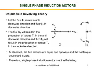
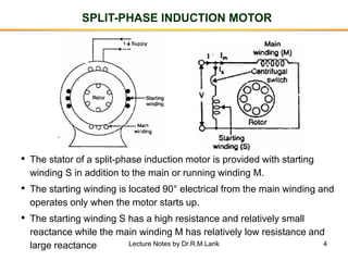
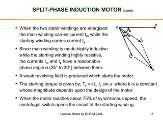


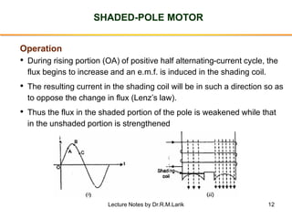


1. Single-phase induction motors use a double-field revolving theory to produce rotation, representing the alternating flux as two counter-rotating fluxes to overcome the lack of self-starting torque in a single-phase motor. 2. Various methods are used to make single-phase induction motors self-starting, including split-phase, capacitor-start and capacitor-run, and shaded-pole techniques. 3. Split-phase motors add a starting winding to introduce a phase difference between currents to produce a rotating field. Capacitor motors improve this effect with a capacitor. Shaded-pole motors use shading coils to shift the magnetic field.


