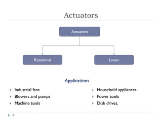
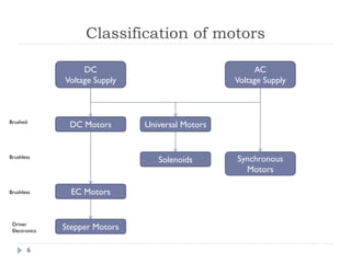
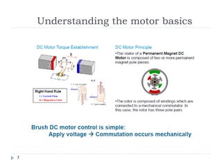
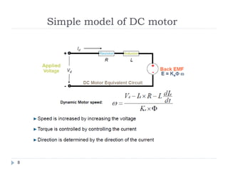
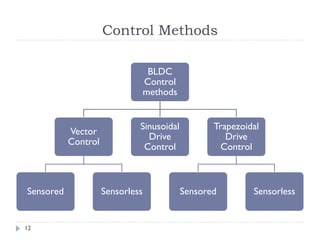
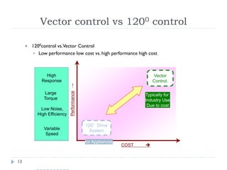
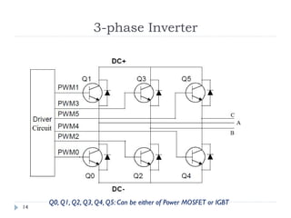
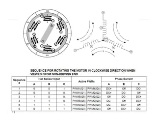
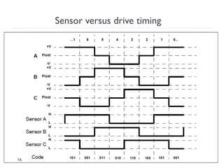
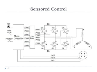
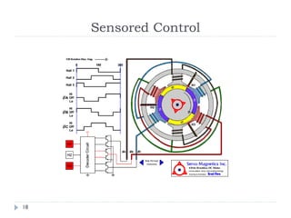
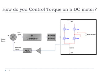
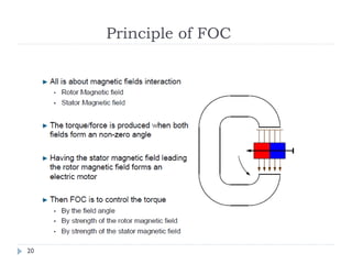
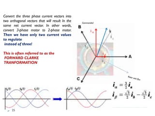
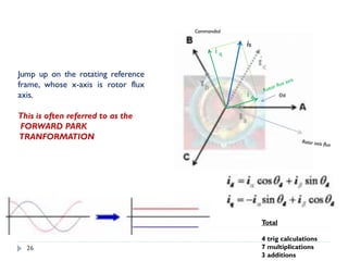
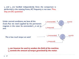
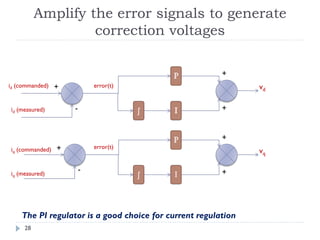
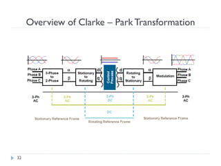
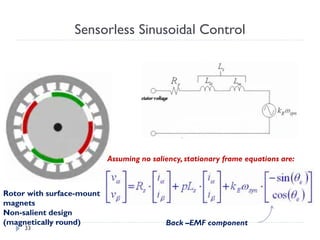
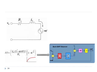
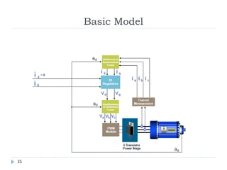
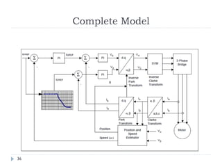
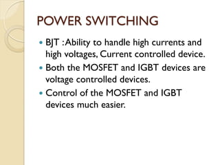
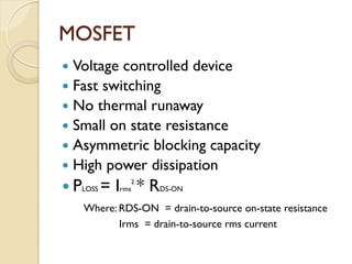
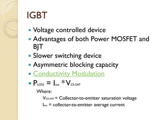
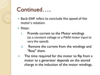
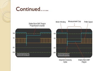
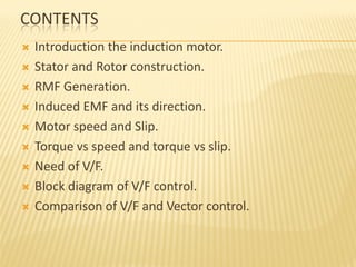
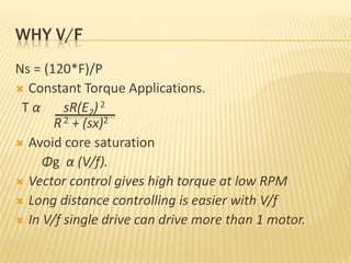
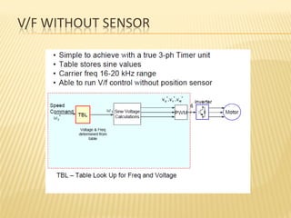
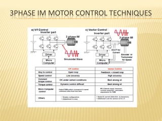
Study of Vector Control Algorithm
and Inverter design for BLDC Motor,
V/f control Algorithm
Project by: Amol Mahurkar, Ayush Modani, Ghanshyam Mali,
Heena Karir, Manoj Autade, Vivek Kumar
Objectives
2
 Working of BLDC Motor
 Different Control Algorithms for BLDC Motor
 Vector Control Algorithm (Sensorless)
 Inverter Design for BLDC Motor
 Parametric Discussion on Inverter Design
 Working of Induction Motor
 Voltage versus Frequency Control Algorithm
Vector Control Algorithm
for BLDC Motors
Sinhgad College of Engineering, Pune
Contents
4
 Classification of motors
 Motor Basics
 BLDC motor and its construction
 BLDC Control methods – Sensored Control
 Clarke/Park Transformation
 Sensorless control
 Vector Control
Actuators
 Industrial fans
 Blowers and pumps
 Machine tools
 Household appliances
 Power tools
 Disk drives.
Actuators
Rotational Linear
Applications
5
Classification of motors
DC
Voltage Supply
AC
Voltage Supply
DC Motors Universal Motors
Solenoids Synchronous
Motors
EC Motors
Stepper Motors
Brushed
Brushless
Brushless
Driver
Electronics
6
Understanding the motor basics
7
Simple model of DC motor
8
BLDC Motor
Merits
Demerits
 Less Maintenance
 Longer Life
 Flat SpeedVs.Torque Characteristics
 High Efficiency
 High Output Power/ Frame Size
 Low Rotor Inertia
 Higher Speed Range
 Low Electric Noise Generation
 Higher Cost of Building
 Complex & Expensive Control
9
Brushless DC motor
 Rotor is Permanent Magnet.
 Stator is Electromagnet.
 Windings is on the stator.
 Three phase supply is given to windings
of stator
 Torque is produced due to interaction
between magnetic field of rotor and
magnetic field produced by current in the
stator.
10
Space vector rotation sequence
11
Control Methods
BLDC
Control
methods
Vector
Control
Sensored Sensorless
Sinusoidal
Drive
Control
Trapezoidal
Drive
Control
Sensored Sensorless
12
Vector control vs 1200 control
Performance→
Variable
Speed
Low Noise,
High Efficiency
Large
Torque
High
Response
COST 
120°Drive
System
Vector
Control.
Typically for
Industry Use
Due to cost
for Appliances
 1200control vs.Vector Control
 Low performance low cost vs. high performance high cost
13
3-phase Inverter
Q0, Q1, Q2, Q3, Q4, Q5: Can be either of Power MOSFET or IGBT
14
15
Sensor versus drive timing
16
Sensored Control
17
Sensored Control
18
How do you Control Torque on a DC motor?
PI
Controller
PWM1
PWM2
ADC
+
-
Desired
Current
Error
Signal
Measured
Current
19
Principle of FOC
20
Maximum Torque per Amp
21
Measure current already flowing in the
motor
Measure ia and ib.
Calculate ic, from Kirchoff’s Law.
A, B, and C axes are “fixed”
with respect to the motor
housing.This reference
frame is also called the
“stationary frame” or “stator frame”.
22
Compare the measured current(vector) with the
desired current(vector), and generate error signals.
isis
Error
We must regulate the current vector magnitude and angle
by regulating ia, ib, and ic.
Commanded
Rotor axis flux
23
Measure the rotor angle to determine if the net current
vector is oriented at 900 with respect to the rotor flux
Θd
Usually accomplished with
a resolver or encoder.
24
Commanded
Convert the three phase current vectors into
two orthogonal vectors that will result In the
same net current vector. In other words,
convert 3-phase motor to 2-phase motor.
Then we have only two current values
to regulate
instead of three!
This is often referred to as the
FORWARD CLARKE
TRANFORMATION
i α
i β
25
Jump up on the rotating reference
frame, whose x-axis is rotor flux
axis.
This is often referred to as the
FORWARD PARK
TRANFORMATION
Commanded
i q
i d Θd
Total
4 trig calculations
7 multiplications
3 additions
26
+
-
id (commanded) error(t)
id (measured)
+
-
iq (commanded) error(t)
iq (measured)
id and iq are handled independently. Since the comparison is
performed in the rotating frame, AC frequency is not seen. Thus,
they are DC quantities!
Under normal conditions, we have all the
d-axis flux we need supplied by the permanent
magnets in the rotor. So commanded id is set to
zero.
This is how much torque we want!
id can however be used to weaken the field of the machine.
iq controls the amount of torque generated by the motor.
27
+
-
error(t)
+
-
iq (commanded) error(t)
iq (measured)
id (commanded)
id (measured)
P
ʃ I
+
+
vd
P
ʃ I
+
+
vq
The PI regulator is a good choice for current regulation
Amplify the error signals to generate
correction voltages
28
Modulate the correction voltages onto the
motor terminals
Commanded
i q
i d Θd
We now need to “jump
off” of the rotating
reference frame
Transfer the voltage vectors back
on to the stationary rectangular
coordinate system.
Reverse ParkTransformation
29
Commanded
Next, we transform the voltage vectors
from the rectangular coordinate
system to three phase vectors.
Reverse ClarkeTransformation
30
Over time, under steady-state conditions, the correction voltages va, vb, and vc
will be sine waves phase shifted by 1200
va
vb vc
31
Overview of Clarke – Park Transformation
32
Rotor with surface-mount
magnets
Non-salient design
(magnetically round)
Assuming no saliency, stationary frame equations are:
Back –EMF component
Sensorless Sinusoidal Control
33
34
Basic Model
35
Complete Model
36
Thankyou
37
Inverters
Contents
 Power switching
 MOSFET
 IGBT
 MOSFET vs IGBT
 Freewheeling Diode
 Back EMF
POWER SWITCHING
 BJT :Ability to handle high currents and
high voltages, Current controlled device.
 Both the MOSFET and IGBT devices are
voltage controlled devices.
 Control of the MOSFET and IGBT
devices much easier.
MOSFET
 Voltage controlled device
 Fast switching
 No thermal runaway
 Small on state resistance
 Asymmetric blocking capacity
 High power dissipation
 PLOSS = Irms
2
* RDS-ON
Where: RDS-ON = drain-to-source on-state resistance
Irms = drain-to-source rms current
IGBT
 Voltage controlled device
 Advantages of both Power MOSFET and
BJT
 Slower switching device
 Asymmetric blocking capacity
 Conductivity Modulation
 PLOSS = Iave *VCE-SAT
Where:
VCE-SAT = Collector-to-emitter saturation voltage
Iave = collector-to-emitter average current
MOSFET vs IGBT
 IGBTs are slower than MOSFETs.
 IGBT has a very low on-state voltage
drop due to conductivity modulation and
has superior on-state current density.
Comparison
Freewheeling Diode
 A Freewheeling diode is a diode used to
eliminate the sudden voltage spike seen
across an inductive load when its supply
voltage is suddenly reduced or removed.
Operation with Freewheeling Diode
Back EMF
 When a BLDC motor rotates, each winding generates a
voltage known as back EMF, which opposes the main
voltage supplied to the windings according to Lenz’s
Law.
 It depends on,
Angular velocity of the rotor
Magnetic field generated by rotor magnets
The number of turns in the stator windings
 Equation is as,
Back EMF = (E) ∝ NlrBω
Continued…..
 Back-EMF refers to conclude the speed of the
motor's rotation.
 Steps:
i. Provide current to the Motor windings
(as a constant voltage or a PWM motor input to
vary the speed).
ii. Remove the current from the windings and
"float" them.
 The time required for the motor to flip from a
motor to a generator depends on the stored
charge in the induction of the motor windings.
Continued…..
THANKYOU
INDUCTION MOTOR
CONTENTS
 Introduction the induction motor.
 Stator and Rotor construction.
 RMF Generation.
 Induced EMF and its direction.
 Motor speed and Slip.
 Torque vs speed and torque vs slip.
 Need of V/F.
 Block diagram of V/F control.
 Comparison of V/F and Vector control.
INDUCTION MOTOR
•Motors operate on principle of Induction and hence the
name “Induction Motors” is used
•Motors also known as AC motors because Alternating
Current (AC) is required
•All AC motors are “brushless”
–No mechanical contacts to wear
–Requires AC source
–If used, inverter creates desired freq and magnitude
of AC
•AC induction motors for lower cost applications
–Single speed applications: fan, blower, pump,
compressor
–No control, just start the AC power source
–Relays are used for ON/OFF
STATOR CONSTROCTION
•Stator has windings with lamination to–Create
strong magnetic field–Maintain continuous flux
•Three phase motor windings are sinusoidal
around the stator to produce a roughly
sinusoidal distribution in flux
•When three phase AC voltages are applied to the
stator windings, a rotating magnetic field is
produced–The rotating magnetic field of the
stator drags the rotor around.
MORE
ROTOR CONSTRUCTION
Squirrel cage construction
–Behaves like shorted 3-
phase windings
–Rotor bars are often
skewed to prevent
cogging
–No magnets or windings
ROTATING MAGNETIC FIELD
INDUCED EMF
 Voltage is induced by following the Lenz Law. So
rotor will rotate in same direction as that of RMF,
to minimize the relative flux cutting.
STATOR
ROTOR
INDUCTION MOTOR SPEED
 So, the IM will always run at a speed lower than the
synchronous speed
 The difference between the motor speed and the
synchronous speed is called the Slip
Where nslip= slip speed
nsync= speed of the magnetic field
nm = mechanical shaft speed of the motor
slip sync mn n n= −
THE SLIP
sync m
sync
n n
s
n
−
=
Where s is the slip
Notice that : if the rotor runs at synchronous speed
s = 0
if the rotor is stationary
s = 1
Slip may be expressed as a percentage by multiplying the above
eq. by 100, notice that the slip is a ratio and doesn’t have units
SLIP CAUSES…..
1) Fr = s*F
2) E2r = s*E2
 Where
 Fr: Frequency of Induced Voltage
 F: Applied Frequency
 E2r: Induced EMF in Rotor
 E2: Max. induced EMF in Secondary.
TORQUE VS SLIP
 T α sR(E2) 2
R 2 + (sx)2
 For LowSlip: T α s.
 For HighSlip: T α 1/s.
 Operated in stable region ie.
Region where(T<Tm)
SLIP(s)
Unstable
Stabl
e
torque
Tm
Tfl
S=
0
S=Sm
S=1
Tm
CONSTANT SUPPLY FREQUENCY
Torque ,speed ,slip char.
SPEED TORQUE CHARACTERISTICS POTTED BASED ON CHANGES
IN SLIP
Explanation
Induced Torque is zero at synchronous speed.
‡
The graph is nearly linear between no load and full load (at near
synchronous speeds).
‡
Max torque is known as pull out torque or breakdown torque
‡
Starting torque is very large.
‡
Torque for a given slip value would change to the square of the applied
voltage.
‡
If the rotor were driven faster than synchronous speed, the motor
would then become a generator.
‡
If we reverse the direction of the stator magnetic field, it would act as
a braking action to the rotor
WHY V/F
Ns = (120*F)/P
 Constant Torque Applications.
T α sR(E2)2
R2 + (sx)2
 Avoid core saturation
Φg α (V/f).
 Vector control gives high torque at low RPM
 Long distance controlling is easier with V/f
 In V/f single drive can drive more than 1 motor.
V/F WITHOUT SENSOR
3PHASE IM MOTOR CONTROL TECHNIQUES
THANKYOU
Q & A ??

Study of Vector Control Algorithm and Inverter design for BLDC Motor, V/f control Algorithm

  • 1.
    Study of VectorControl Algorithm and Inverter design for BLDC Motor, V/f control Algorithm Project by: Amol Mahurkar, Ayush Modani, Ghanshyam Mali, Heena Karir, Manoj Autade, Vivek Kumar
  • 2.
    Objectives 2  Working ofBLDC Motor  Different Control Algorithms for BLDC Motor  Vector Control Algorithm (Sensorless)  Inverter Design for BLDC Motor  Parametric Discussion on Inverter Design  Working of Induction Motor  Voltage versus Frequency Control Algorithm
  • 3.
    Vector Control Algorithm forBLDC Motors Sinhgad College of Engineering, Pune
  • 4.
    Contents 4  Classification ofmotors  Motor Basics  BLDC motor and its construction  BLDC Control methods – Sensored Control  Clarke/Park Transformation  Sensorless control  Vector Control
  • 5.
    Actuators  Industrial fans Blowers and pumps  Machine tools  Household appliances  Power tools  Disk drives. Actuators Rotational Linear Applications 5
  • 6.
    Classification of motors DC VoltageSupply AC Voltage Supply DC Motors Universal Motors Solenoids Synchronous Motors EC Motors Stepper Motors Brushed Brushless Brushless Driver Electronics 6
  • 7.
  • 8.
    Simple model ofDC motor 8
  • 9.
    BLDC Motor Merits Demerits  LessMaintenance  Longer Life  Flat SpeedVs.Torque Characteristics  High Efficiency  High Output Power/ Frame Size  Low Rotor Inertia  Higher Speed Range  Low Electric Noise Generation  Higher Cost of Building  Complex & Expensive Control 9
  • 10.
    Brushless DC motor Rotor is Permanent Magnet.  Stator is Electromagnet.  Windings is on the stator.  Three phase supply is given to windings of stator  Torque is produced due to interaction between magnetic field of rotor and magnetic field produced by current in the stator. 10
  • 11.
  • 12.
  • 13.
    Vector control vs1200 control Performance→ Variable Speed Low Noise, High Efficiency Large Torque High Response COST  120°Drive System Vector Control. Typically for Industry Use Due to cost for Appliances  1200control vs.Vector Control  Low performance low cost vs. high performance high cost 13
  • 14.
    3-phase Inverter Q0, Q1,Q2, Q3, Q4, Q5: Can be either of Power MOSFET or IGBT 14
  • 15.
  • 16.
  • 17.
  • 18.
  • 19.
    How do youControl Torque on a DC motor? PI Controller PWM1 PWM2 ADC + - Desired Current Error Signal Measured Current 19
  • 20.
  • 21.
  • 22.
    Measure current alreadyflowing in the motor Measure ia and ib. Calculate ic, from Kirchoff’s Law. A, B, and C axes are “fixed” with respect to the motor housing.This reference frame is also called the “stationary frame” or “stator frame”. 22
  • 23.
    Compare the measuredcurrent(vector) with the desired current(vector), and generate error signals. isis Error We must regulate the current vector magnitude and angle by regulating ia, ib, and ic. Commanded Rotor axis flux 23
  • 24.
    Measure the rotorangle to determine if the net current vector is oriented at 900 with respect to the rotor flux Θd Usually accomplished with a resolver or encoder. 24
  • 25.
    Commanded Convert the threephase current vectors into two orthogonal vectors that will result In the same net current vector. In other words, convert 3-phase motor to 2-phase motor. Then we have only two current values to regulate instead of three! This is often referred to as the FORWARD CLARKE TRANFORMATION i α i β 25
  • 26.
    Jump up onthe rotating reference frame, whose x-axis is rotor flux axis. This is often referred to as the FORWARD PARK TRANFORMATION Commanded i q i d Θd Total 4 trig calculations 7 multiplications 3 additions 26
  • 27.
    + - id (commanded) error(t) id(measured) + - iq (commanded) error(t) iq (measured) id and iq are handled independently. Since the comparison is performed in the rotating frame, AC frequency is not seen. Thus, they are DC quantities! Under normal conditions, we have all the d-axis flux we need supplied by the permanent magnets in the rotor. So commanded id is set to zero. This is how much torque we want! id can however be used to weaken the field of the machine. iq controls the amount of torque generated by the motor. 27
  • 28.
    + - error(t) + - iq (commanded) error(t) iq(measured) id (commanded) id (measured) P ʃ I + + vd P ʃ I + + vq The PI regulator is a good choice for current regulation Amplify the error signals to generate correction voltages 28
  • 29.
    Modulate the correctionvoltages onto the motor terminals Commanded i q i d Θd We now need to “jump off” of the rotating reference frame Transfer the voltage vectors back on to the stationary rectangular coordinate system. Reverse ParkTransformation 29
  • 30.
    Commanded Next, we transformthe voltage vectors from the rectangular coordinate system to three phase vectors. Reverse ClarkeTransformation 30
  • 31.
    Over time, understeady-state conditions, the correction voltages va, vb, and vc will be sine waves phase shifted by 1200 va vb vc 31
  • 32.
    Overview of Clarke– Park Transformation 32
  • 33.
    Rotor with surface-mount magnets Non-salientdesign (magnetically round) Assuming no saliency, stationary frame equations are: Back –EMF component Sensorless Sinusoidal Control 33
  • 34.
  • 35.
  • 36.
  • 37.
  • 38.
  • 39.
    Contents  Power switching MOSFET  IGBT  MOSFET vs IGBT  Freewheeling Diode  Back EMF
  • 40.
    POWER SWITCHING  BJT:Ability to handle high currents and high voltages, Current controlled device.  Both the MOSFET and IGBT devices are voltage controlled devices.  Control of the MOSFET and IGBT devices much easier.
  • 41.
    MOSFET  Voltage controlleddevice  Fast switching  No thermal runaway  Small on state resistance  Asymmetric blocking capacity  High power dissipation  PLOSS = Irms 2 * RDS-ON Where: RDS-ON = drain-to-source on-state resistance Irms = drain-to-source rms current
  • 42.
    IGBT  Voltage controlleddevice  Advantages of both Power MOSFET and BJT  Slower switching device  Asymmetric blocking capacity  Conductivity Modulation  PLOSS = Iave *VCE-SAT Where: VCE-SAT = Collector-to-emitter saturation voltage Iave = collector-to-emitter average current
  • 43.
    MOSFET vs IGBT IGBTs are slower than MOSFETs.  IGBT has a very low on-state voltage drop due to conductivity modulation and has superior on-state current density.
  • 44.
  • 45.
    Freewheeling Diode  AFreewheeling diode is a diode used to eliminate the sudden voltage spike seen across an inductive load when its supply voltage is suddenly reduced or removed.
  • 46.
  • 47.
    Back EMF  Whena BLDC motor rotates, each winding generates a voltage known as back EMF, which opposes the main voltage supplied to the windings according to Lenz’s Law.  It depends on, Angular velocity of the rotor Magnetic field generated by rotor magnets The number of turns in the stator windings  Equation is as, Back EMF = (E) ∝ NlrBω
  • 48.
    Continued…..  Back-EMF refersto conclude the speed of the motor's rotation.  Steps: i. Provide current to the Motor windings (as a constant voltage or a PWM motor input to vary the speed). ii. Remove the current from the windings and "float" them.  The time required for the motor to flip from a motor to a generator depends on the stored charge in the induction of the motor windings.
  • 49.
  • 50.
  • 51.
  • 52.
    CONTENTS  Introduction theinduction motor.  Stator and Rotor construction.  RMF Generation.  Induced EMF and its direction.  Motor speed and Slip.  Torque vs speed and torque vs slip.  Need of V/F.  Block diagram of V/F control.  Comparison of V/F and Vector control.
  • 53.
    INDUCTION MOTOR •Motors operateon principle of Induction and hence the name “Induction Motors” is used •Motors also known as AC motors because Alternating Current (AC) is required •All AC motors are “brushless” –No mechanical contacts to wear –Requires AC source –If used, inverter creates desired freq and magnitude of AC •AC induction motors for lower cost applications –Single speed applications: fan, blower, pump, compressor –No control, just start the AC power source –Relays are used for ON/OFF
  • 54.
    STATOR CONSTROCTION •Stator haswindings with lamination to–Create strong magnetic field–Maintain continuous flux •Three phase motor windings are sinusoidal around the stator to produce a roughly sinusoidal distribution in flux •When three phase AC voltages are applied to the stator windings, a rotating magnetic field is produced–The rotating magnetic field of the stator drags the rotor around. MORE
  • 55.
    ROTOR CONSTRUCTION Squirrel cageconstruction –Behaves like shorted 3- phase windings –Rotor bars are often skewed to prevent cogging –No magnets or windings
  • 56.
  • 57.
    INDUCED EMF  Voltageis induced by following the Lenz Law. So rotor will rotate in same direction as that of RMF, to minimize the relative flux cutting. STATOR ROTOR
  • 58.
    INDUCTION MOTOR SPEED So, the IM will always run at a speed lower than the synchronous speed  The difference between the motor speed and the synchronous speed is called the Slip Where nslip= slip speed nsync= speed of the magnetic field nm = mechanical shaft speed of the motor slip sync mn n n= −
  • 59.
    THE SLIP sync m sync nn s n − = Where s is the slip Notice that : if the rotor runs at synchronous speed s = 0 if the rotor is stationary s = 1 Slip may be expressed as a percentage by multiplying the above eq. by 100, notice that the slip is a ratio and doesn’t have units
  • 60.
    SLIP CAUSES….. 1) Fr= s*F 2) E2r = s*E2  Where  Fr: Frequency of Induced Voltage  F: Applied Frequency  E2r: Induced EMF in Rotor  E2: Max. induced EMF in Secondary.
  • 61.
    TORQUE VS SLIP T α sR(E2) 2 R 2 + (sx)2  For LowSlip: T α s.  For HighSlip: T α 1/s.  Operated in stable region ie. Region where(T<Tm) SLIP(s) Unstable Stabl e torque Tm Tfl S= 0 S=Sm S=1 Tm
  • 62.
  • 63.
    SPEED TORQUE CHARACTERISTICSPOTTED BASED ON CHANGES IN SLIP Explanation
  • 64.
    Induced Torque iszero at synchronous speed. ‡ The graph is nearly linear between no load and full load (at near synchronous speeds). ‡ Max torque is known as pull out torque or breakdown torque ‡ Starting torque is very large. ‡ Torque for a given slip value would change to the square of the applied voltage. ‡ If the rotor were driven faster than synchronous speed, the motor would then become a generator. ‡ If we reverse the direction of the stator magnetic field, it would act as a braking action to the rotor
  • 65.
    WHY V/F Ns =(120*F)/P  Constant Torque Applications. T α sR(E2)2 R2 + (sx)2  Avoid core saturation Φg α (V/f).  Vector control gives high torque at low RPM  Long distance controlling is easier with V/f  In V/f single drive can drive more than 1 motor.
  • 66.
  • 67.
    3PHASE IM MOTORCONTROL TECHNIQUES
  • 68.
  • 69.