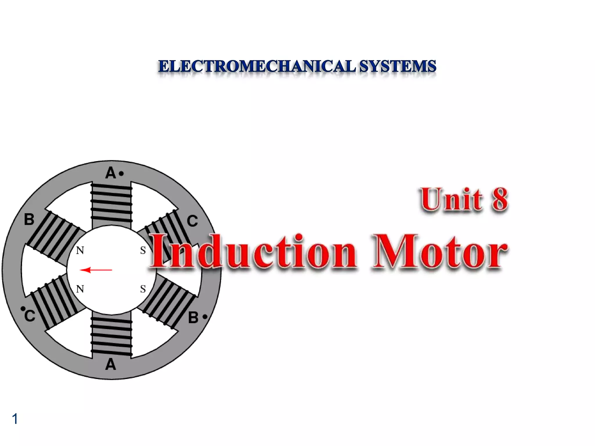
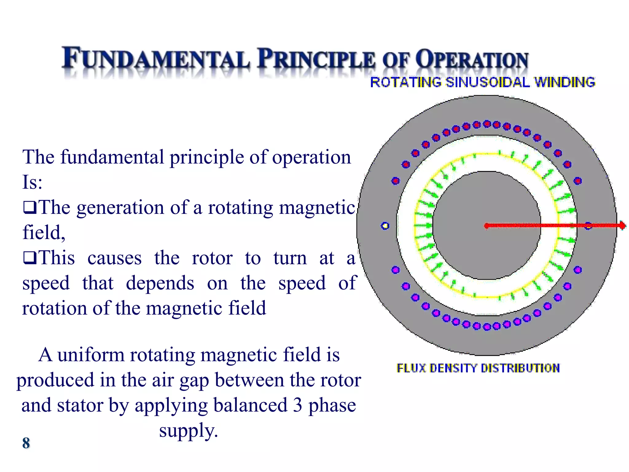
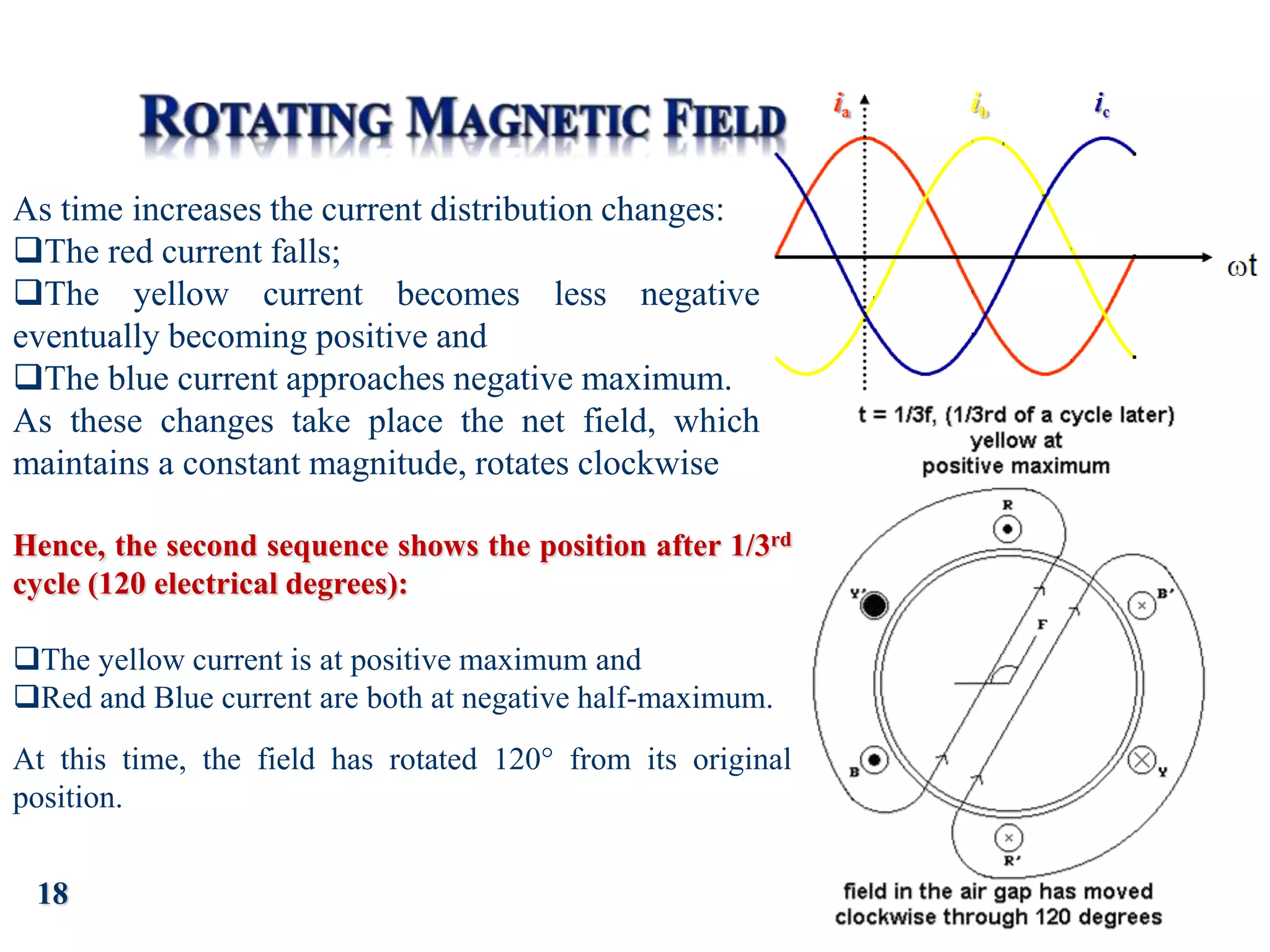
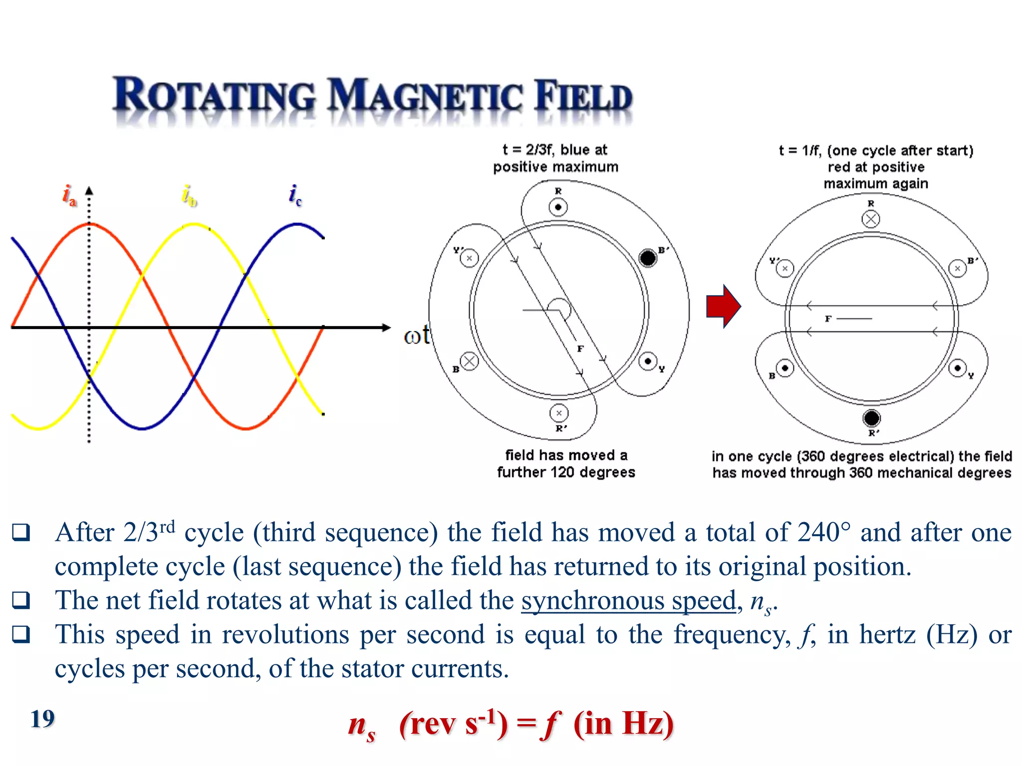
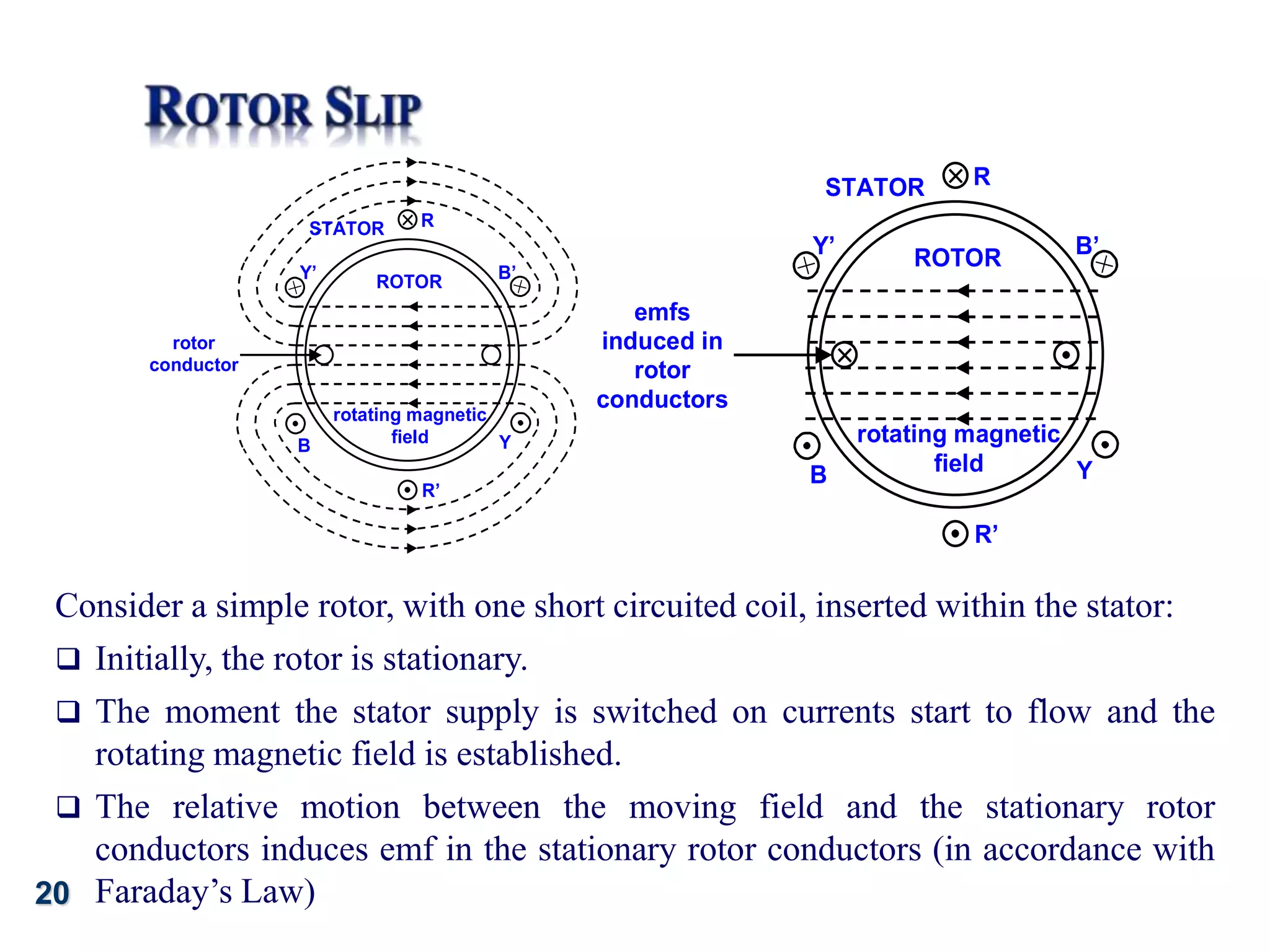
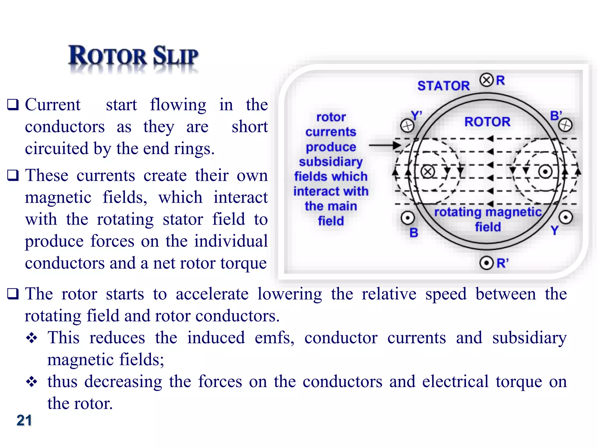
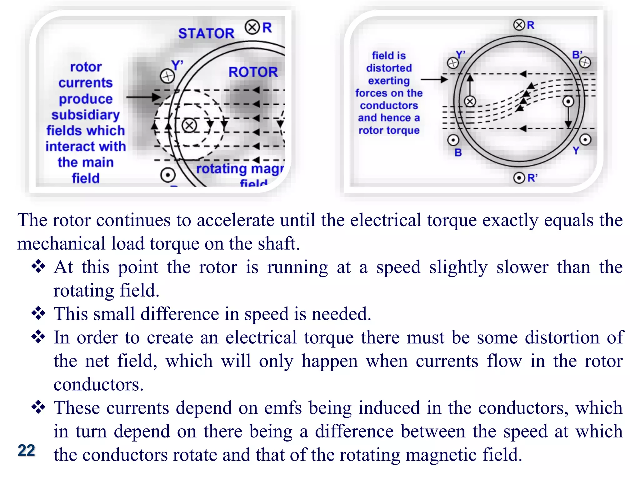
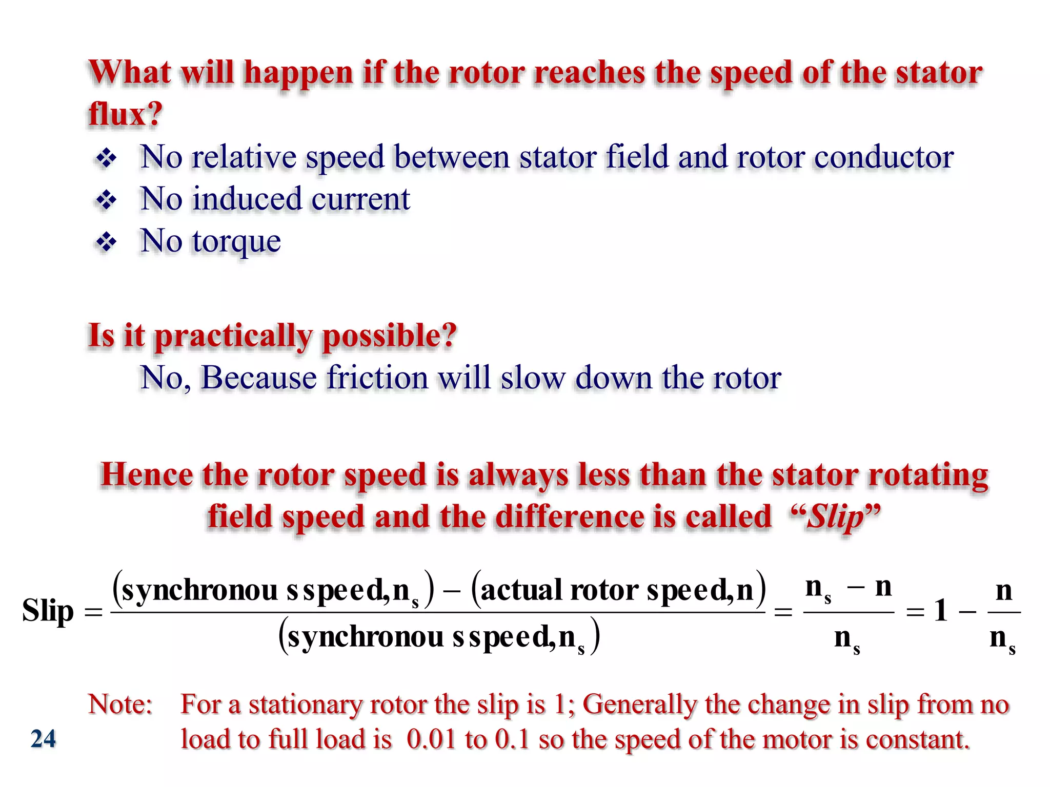
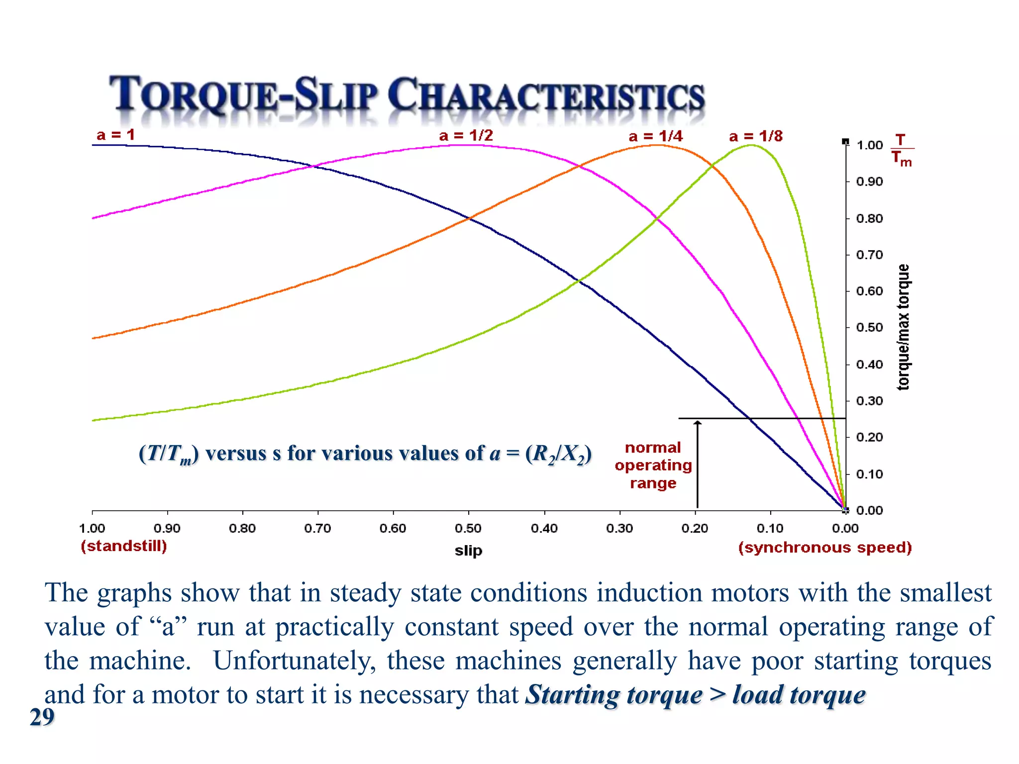
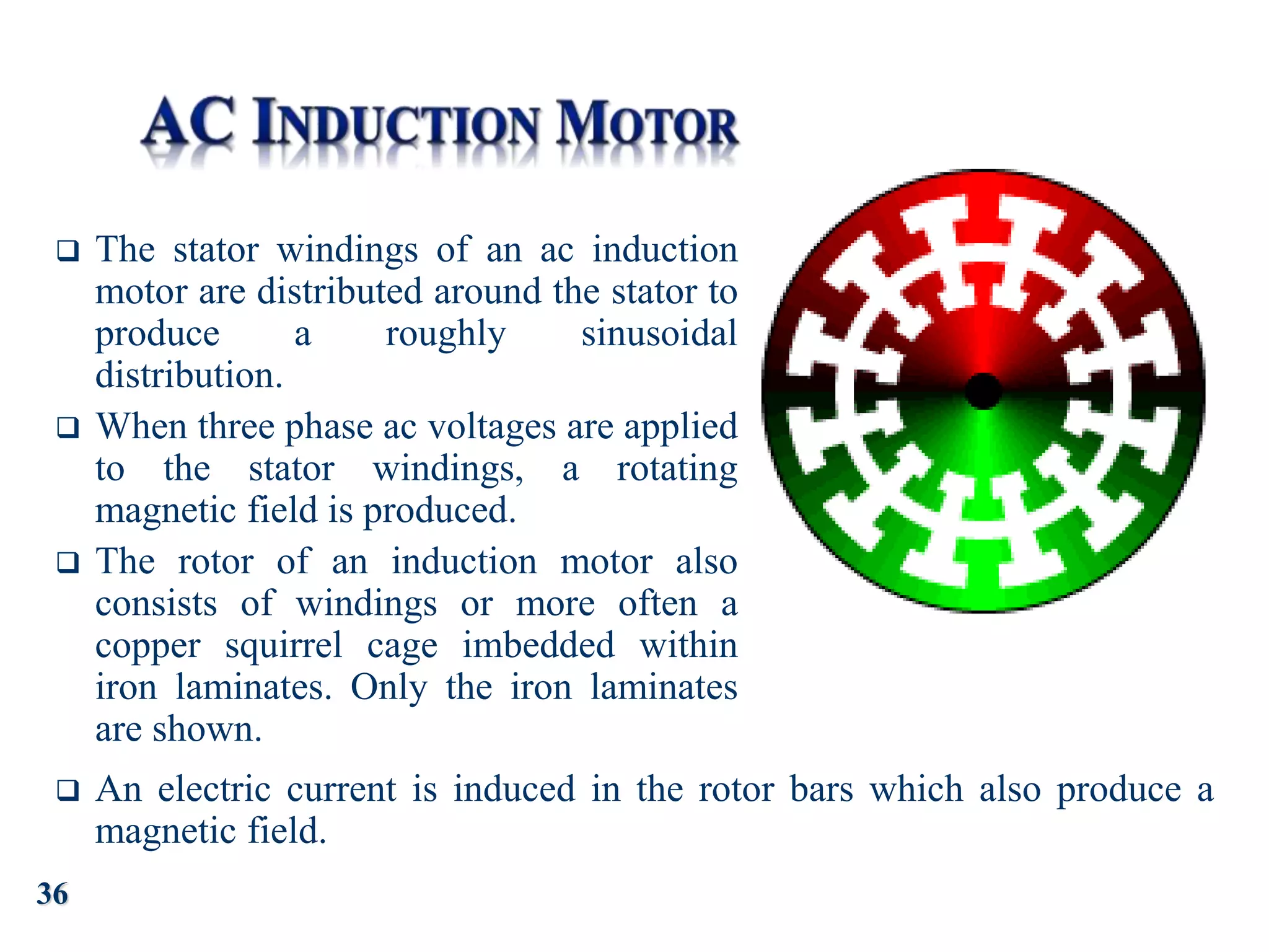
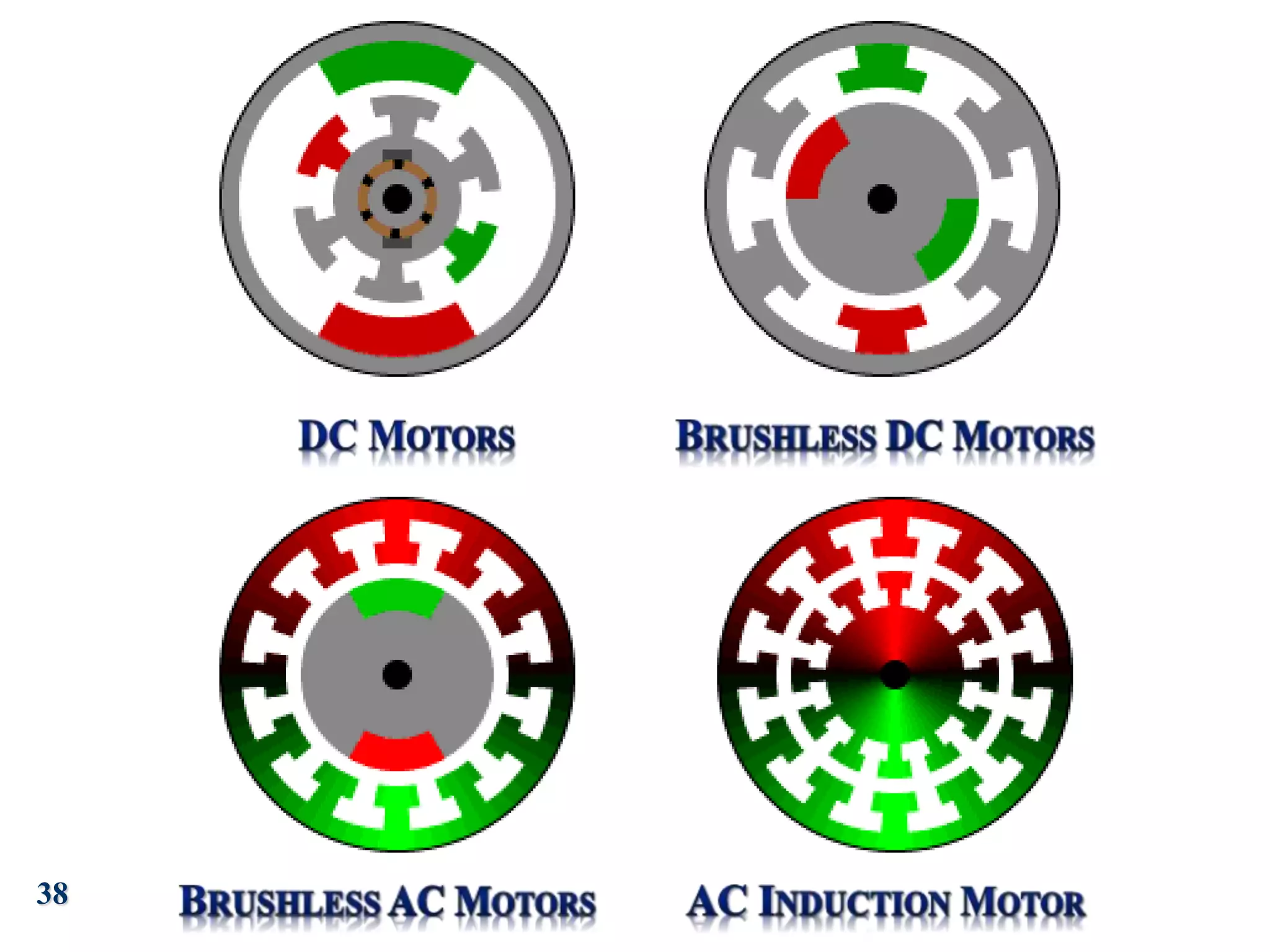
1
2
This unit explains the principle of operation of 3- phase induction
motor and its applications
After completing this unit you will be able to Calculate:
 Torque – speed characteristics
 Mechanical output power
 Induction Motor Construction
 Principles of Operation
 Torque
 Torque vs. Slip Characteristics
 Multi-pole Motors
3
From last week, it was obvious that it is possible to obtain a wide
range of performance characteristics from DC machines
(motorsgenerators)
Now!
The question is do we insist on using DC, which requires the use of additional
hardware to rectify and regulate the DC supplies?
Or
Should we consider using AC, which is more convenient as it is readily available in
single or multi-phase form.
The answer to this question is yes we should consider using AC.
Then we should consider AC machines, and study their
Basic operation (that is synchronous and induction),
Advantages and disadvantages, in comparison with direct-current machines.
Structure
 The stator is the outside stationary part of the
motor.
 The rotor is the inner rotating part.
 In the animation:
 Red represents a magnet or winding with a North
polarization,
 Green represents a magnet or winding with a
South polarization.
 Opposite, red and green, polarities attract.
Operation
 As the rotor reaches alignment, the brushes move across the commutator
contacts and energize the next winding.
 In the animation:
 The commutator contacts are brown,
 The brushes are dark grey.
 A yellow spark shows when the brushes switch to the next winding.
4
5
Just Like dc Machines, ac Machines also consist of
Stator, and
Rotor.
 The outer stationary steel frame enclosing a hollow, cylindrical core.
 A large number of circular silicon steel laminations with slots cut in the inner
circumference.
 Three phase windings mutually displaced by 120 are wound in these slots.
 The greater the number of poles, the lesser is the speed and vice-versa.
 Three phase supply induces rotating magnetic field.
 Air gap between the stator and rotor ranges 0.4mm to 4mm, determines the
power of the motor
6
7
 Squirrel Cage is the most common form of rotor:
 Laminated cylindrical core with parallel slots at the outer
periphery
 Copper or aluminium bars are placed in the slots
 All the bars are welded at each end by metal rings called
“End rings”
 End rings are sometimes castellated to facilitate cooling.
 It is not connected to the supply and operates on the
transformer principle
 Advantages: This is a simple and robust
construction
 Disadvantage: Low starting torque as it is not
possible to
add external resistance.
 Wound
 Laminated cylindrical core
 Has star connected three phase winding
 Open ends are connected to three separate
insulated slip rings
 External resistances are connected to increase
the starting torque
8
The fundamental principle of operation
Is:
The generation of a rotating magnetic
field,
This causes the rotor to turn at a
speed that depends on the speed of
rotation of the magnetic field
A uniform rotating magnetic field is
produced in the air gap between the rotor
and stator by applying balanced 3 phase
supply.
9
 The stator supports windings a-a, b-b and c-c, which are
geometrically spaced 120◦ apart.
 Therefore, the currents generated by a 3-phase source are also spaced
by 120◦.
10
The phase voltages referenced to the neutral terminal, would then
be given by the expressions
11
 The coils are arranged so that the flux distribution generated by any
one winding is approximately sinusoidal.
 Since the coils are spaced 120◦ apart, the flux distribution resulting
from the sum of the contributions of the three windings is the sum
of the fluxes due to the separate windings.
12
13
 Since the resultant flux is generated by the currents,
the speed of rotation of the flux must be related to the
frequency of the sinusoidal phase currents.
 The number of magnetic poles resulting from the
stator winding configuration is two. However, it is
possible to configure the windings so that they have
more poles.
In general,
 The speed of the rotating magnetic field is determined
by the frequency of the excitation current, f , and
 By the number of poles present in the stator, p,
according to the equation
rev/min
f
p
120
ns 
rev/min
p
f
2
60
n
2 s
s





where ns (or ωs)
is usually called
the synchronous
speed.
14
 The stator magnetic field rotates in an AC machine, and
 therefore the rotor cannot “catch up” with the stator field and is
in constant pursuit of it.
 The speed of rotation of the rotor will therefore depend on the
number of magnetic poles present in the stator and in the rotor.
 The magnitude of the torque produced is a function of the angle γ
between the stator and rotor magnetic fields
 The number of stator and rotor poles must be identical if any
torque is to be generated.
15
It is important to generate a constant electromagnetic torque to
avoid torque pulsations
Pulsations could lead to undesired mechanical vibration in the
motor itself and in other mechanical components attached to the
motor (e.g., mechanical loads, such as spindles or belt drives).
t
ia ib ic
)
120
cos(ωo
I
i
)
120
cos(ωo
I
i
cosωo
I
i
o
m
c
o
m
b
m
a





A Current Maximum B Current Maximum C Current Maximum
Time
Direction of B
16
17
Assume that the current waveforms are as in
the top Figure.
At the moment t = 0:
 Red phase current is at positive
maximum
 Yellow and Blue phase currents are
both at negative half-maximum.
Each of these currents produces a
magnetic field. These fields interact to
form the net field shown in the first
sequence in the Figure.
The magnetic field resembles that associated
with a two pole bar magnet. As a consequence
the machine is called a 2-pole motor.
18
As time increases the current distribution changes:
The red current falls;
The yellow current becomes less negative
eventually becoming positive and
The blue current approaches negative maximum.
As these changes take place the net field, which
maintains a constant magnitude, rotates clockwise
Hence, the second sequence shows the position after 1/3rd
cycle (120 electrical degrees):
The yellow current is at positive maximum and
Red and Blue current are both at negative half-maximum.
At this time, the field has rotated 120 from its original
position.
19
 After 2/3rd cycle (third sequence) the field has moved a total of 240 and after one
complete cycle (last sequence) the field has returned to its original position.
 The net field rotates at what is called the synchronous speed, ns.
 This speed in revolutions per second is equal to the frequency, f, in hertz (Hz) or
cycles per second, of the stator currents.
ns (rev s-1) = f (in Hz)
20
R
R’
B Y
Y’ B’
ROTOR
STATOR
rotating magnetic
field
rotor
conductor
R
R’
B Y
Y’ B’
ROTOR
STATOR
rotating magnetic
field
emfs
induced in
rotor
conductors
Consider a simple rotor, with one short circuited coil, inserted within the stator:
 Initially, the rotor is stationary.
 The moment the stator supply is switched on currents start to flow and the
rotating magnetic field is established.
 The relative motion between the moving field and the stationary rotor
conductors induces emf in the stationary rotor conductors (in accordance with
Faraday’s Law)
21
 Current start flowing in the
conductors as they are short
circuited by the end rings.
 These currents create their own
magnetic fields, which interact
with the rotating stator field to
produce forces on the individual
conductors and a net rotor torque
 The rotor starts to accelerate lowering the relative speed between the
rotating field and rotor conductors.
 This reduces the induced emfs, conductor currents and subsidiary
magnetic fields;
 thus decreasing the forces on the conductors and electrical torque on
the rotor.
22
The rotor continues to accelerate until the electrical torque exactly equals the
mechanical load torque on the shaft.
 At this point the rotor is running at a speed slightly slower than the
rotating field.
 This small difference in speed is needed.
 In order to create an electrical torque there must be some distortion of
the net field, which will only happen when currents flow in the rotor
conductors.
 These currents depend on emfs being induced in the conductors, which
in turn depend on there being a difference between the speed at which
the conductors rotate and that of the rotating magnetic field.
23
This difference in speed is expressed as a ratio known as the (per unit) slip.
Remembering that the rotational speed of magnetic field is known formally as the
synchronous speed, the slip is defined as
For most machines the value of the slip varies between around 0.01 on no-load,
(when the only torque required is to overcome friction at the bearings) and 0.10 at
full load.
   
 
s
s
n
speed,
s
synchronou
n
speed,
rotor
actual
n
speed,
s
synchronou
Slip


24
Hence the rotor speed is always less than the stator rotating
field speed and the difference is called “Slip”
   
  s
s
s
s
s
n
n
1
n
n
n
n
speed,
s
synchronou
n
speed,
rotor
actual
n
speed,
s
synchronou
Slip 





Note: For a stationary rotor the slip is 1; Generally the change in slip from no
load to full load is 0.01 to 0.1 so the speed of the motor is constant.
What will happen if the rotor reaches the speed of the stator
flux?
Is it practically possible?
 No relative speed between stator field and rotor conductor
 No induced current
 No torque
No, Because friction will slow down the rotor
25
 Nm
s
a
X
as
E
ω
3
T
Torque, 2
2
2
2
2



Where E2 = emf induced in rotor winding at standstill
s = per unit slip
 = 2f (f = supply frequency in Hz)
X2 = standstill rotor reactance per phase
a = (R2 = rotor resistance per phase)
Mechanical output power = Torque  Angular velocity of rotor
Pm = T  (2n)
Pm = 2Tns(1-s)
But ns = f and  = 2f
Pm = T(1-s) watts
s
a
X
s
as
E
)
(
)
1
(
3
2
2
2
2
2



2
2
X
R
26
A 3-phase 415V 2 pole 50Hz induction motor has an
effective stator : rotor turns ratio of 2:1, rotor resistance
0.15/phase and rotor standstill reactance 0.75/phase. The
motor runs at 2900 rev min-1. Calculate
– a) per unit slip
– b) torque
– c) mechanical output power
27
Per Unit Slip
Torque
Mechanical output power
28
 Starting Torque
– On starting, rotor speed n = 0 and slip, s = 1
 Maximum Torque
Nm
a
X
a
E
Tstart
)
1
(
3
2
2
2
2




0
)
(
)
(
3
2
2
2
2
2
2
2
2






s
a
s
a
a
X
E
ds
dT

i.e. when a = s
Nm
X
E
Tm
2
2
2
3
2
1




29
(T/Tm) versus s for various values of a = (R2/X2)
The graphs show that in steady state conditions induction motors with the smallest
value of “a” run at practically constant speed over the normal operating range of
the machine. Unfortunately, these machines generally have poor starting torques
and for a motor to start it is necessary that Starting torque > load torque
30
31
No of poles Pole Pairs
Synchronous speed @ frequency = 50Hz
rev s-1 (= ns) rev min-1
2 1 50 3000
4 2 25 1500
6 3 16.67 1000
8 4 12.5 750
2p p (50/p) = (f/p) (3000/p)
32
33
 Previously, it was shown that the synchronous speed of
an induction motor is totally dependent on the frequency
of the stator currents.
 As the rotor speed is dependent on the synchronous speed then
the former is also dependent on the supply frequency.
 By using an inverter to provide a variable frequency
supply the speed can be controlled.
 Inverters with ratings up to 750 kW can provide control over
speed ranges varying from 10:1 to 100:1.
 These are most commonly used in pumping applications,
synchronised paper presses and conveyor systems.
A brushless dc motor has:
 A rotor with permanent magnets, and
 A stator with windings.
 It is essentially a dc motor turned
inside out.
 The control electronics replaces the function of the
commutator and energize the proper winding.
34
 A brushless ac motor is driven with
ac sine wave voltages.
 The permanent magnet rotor rotates
synchronous to the rotating magnetic
field.
 The rotating magnetic field is
illustrated using a red and green
gradient.
 An actual simulation of the magnetic field would show a far
more complex magnetic field.
35
 The stator windings of an ac induction
motor are distributed around the stator to
produce a roughly sinusoidal
distribution.
 When three phase ac voltages are applied
to the stator windings, a rotating
magnetic field is produced.
 The rotor of an induction motor also
consists of windings or more often a
copper squirrel cage imbedded within
iron laminates. Only the iron laminates
are shown.
 An electric current is induced in the rotor bars which also produce a
magnetic field.
36
 The rotating magnetic field of the stator drags the rotor around.
The rotor does not quite keep up with the rotating magnetic field
of the stator.
 It falls behind or slips as the field rotates.
 Here, the slip has been greatly exaggerated to enable visualization
of this concept. A real induction motor only slips a few percent.
37
38
39
 In this unit we explained the principle of operation of 3- phase induction
motor and its applications, with particular focus on Induction Motors:
 Its Construction
 Principles of Operation
 Torque
 Torque vs. Slip Characteristics
 Multi-pole Motors
 We also briefly highlighted the difference between popular DC and
AC Machines:
 Conventional DC,
 Brushless DC,
 Brushless AC
 Induction Motor
40
Q1 A 3-phase 440V 4pole 50Hz induction motor has a rotor resistance of 0.05/phase and a rotor
standstill reactance of 0.5/phase. The standstill rotor emf is volts (phase value).
Calculate the maximum torque produced and the corresponding slip. 91.67Nm, 0.1
 
3
120/
Q2 A 3-phase 415V 4pole 50Hz induction motor which has an effective stator: rotor turns ratio of 2:1,
rotor resistance 0.2/phase, rotor standstill reactance 1/phase, runs at 1450rev min-1.
Calculate:-
a per unit slip
b mechanical output power
c total torque developed 0.0333, 6743W, 44.4Nm
Q3 A 3-phase 220V 6 pole 60Hz induction motor with an effective stator:rotor turns ratio of 4:1, rotor
resistance 0.1 and standstill rotor reactance 1.0 drives a constant load torque of 10Nm.
Calculate the slip and operating speed. 0.0543, 1136rev min-1
Q4 A 3-phase 415V 6pole 50Hz inductor motor has effective stator:rotor turns ratio of 3:1, rotor
resistance 0.1 and rotor standstill reactance 0.4.
Calculate the starting torque. At full load the slip is 0.04. Calculate the torque and mechanical output
power. 107.5Nm; 71.2Nm, 7.17kw

Induction_Motor.ppt

  • 1.
  • 2.
    2 This unit explainsthe principle of operation of 3- phase induction motor and its applications After completing this unit you will be able to Calculate:  Torque – speed characteristics  Mechanical output power  Induction Motor Construction  Principles of Operation  Torque  Torque vs. Slip Characteristics  Multi-pole Motors
  • 3.
    3 From last week,it was obvious that it is possible to obtain a wide range of performance characteristics from DC machines (motorsgenerators) Now! The question is do we insist on using DC, which requires the use of additional hardware to rectify and regulate the DC supplies? Or Should we consider using AC, which is more convenient as it is readily available in single or multi-phase form. The answer to this question is yes we should consider using AC. Then we should consider AC machines, and study their Basic operation (that is synchronous and induction), Advantages and disadvantages, in comparison with direct-current machines.
  • 4.
    Structure  The statoris the outside stationary part of the motor.  The rotor is the inner rotating part.  In the animation:  Red represents a magnet or winding with a North polarization,  Green represents a magnet or winding with a South polarization.  Opposite, red and green, polarities attract. Operation  As the rotor reaches alignment, the brushes move across the commutator contacts and energize the next winding.  In the animation:  The commutator contacts are brown,  The brushes are dark grey.  A yellow spark shows when the brushes switch to the next winding. 4
  • 5.
    5 Just Like dcMachines, ac Machines also consist of Stator, and Rotor.
  • 6.
     The outerstationary steel frame enclosing a hollow, cylindrical core.  A large number of circular silicon steel laminations with slots cut in the inner circumference.  Three phase windings mutually displaced by 120 are wound in these slots.  The greater the number of poles, the lesser is the speed and vice-versa.  Three phase supply induces rotating magnetic field.  Air gap between the stator and rotor ranges 0.4mm to 4mm, determines the power of the motor 6
  • 7.
    7  Squirrel Cageis the most common form of rotor:  Laminated cylindrical core with parallel slots at the outer periphery  Copper or aluminium bars are placed in the slots  All the bars are welded at each end by metal rings called “End rings”  End rings are sometimes castellated to facilitate cooling.  It is not connected to the supply and operates on the transformer principle  Advantages: This is a simple and robust construction  Disadvantage: Low starting torque as it is not possible to add external resistance.  Wound  Laminated cylindrical core  Has star connected three phase winding  Open ends are connected to three separate insulated slip rings  External resistances are connected to increase the starting torque
  • 8.
    8 The fundamental principleof operation Is: The generation of a rotating magnetic field, This causes the rotor to turn at a speed that depends on the speed of rotation of the magnetic field A uniform rotating magnetic field is produced in the air gap between the rotor and stator by applying balanced 3 phase supply.
  • 9.
    9  The statorsupports windings a-a, b-b and c-c, which are geometrically spaced 120◦ apart.  Therefore, the currents generated by a 3-phase source are also spaced by 120◦.
  • 10.
    10 The phase voltagesreferenced to the neutral terminal, would then be given by the expressions
  • 11.
    11  The coilsare arranged so that the flux distribution generated by any one winding is approximately sinusoidal.  Since the coils are spaced 120◦ apart, the flux distribution resulting from the sum of the contributions of the three windings is the sum of the fluxes due to the separate windings.
  • 12.
  • 13.
    13  Since theresultant flux is generated by the currents, the speed of rotation of the flux must be related to the frequency of the sinusoidal phase currents.  The number of magnetic poles resulting from the stator winding configuration is two. However, it is possible to configure the windings so that they have more poles. In general,  The speed of the rotating magnetic field is determined by the frequency of the excitation current, f , and  By the number of poles present in the stator, p, according to the equation rev/min f p 120 ns  rev/min p f 2 60 n 2 s s      where ns (or ωs) is usually called the synchronous speed.
  • 14.
    14  The statormagnetic field rotates in an AC machine, and  therefore the rotor cannot “catch up” with the stator field and is in constant pursuit of it.  The speed of rotation of the rotor will therefore depend on the number of magnetic poles present in the stator and in the rotor.  The magnitude of the torque produced is a function of the angle γ between the stator and rotor magnetic fields  The number of stator and rotor poles must be identical if any torque is to be generated.
  • 15.
    15 It is importantto generate a constant electromagnetic torque to avoid torque pulsations Pulsations could lead to undesired mechanical vibration in the motor itself and in other mechanical components attached to the motor (e.g., mechanical loads, such as spindles or belt drives).
  • 16.
    t ia ib ic ) 120 cos(ωo I i ) 120 cos(ωo I i cosωo I i o m c o m b m a      ACurrent Maximum B Current Maximum C Current Maximum Time Direction of B 16
  • 17.
    17 Assume that thecurrent waveforms are as in the top Figure. At the moment t = 0:  Red phase current is at positive maximum  Yellow and Blue phase currents are both at negative half-maximum. Each of these currents produces a magnetic field. These fields interact to form the net field shown in the first sequence in the Figure. The magnetic field resembles that associated with a two pole bar magnet. As a consequence the machine is called a 2-pole motor.
  • 18.
    18 As time increasesthe current distribution changes: The red current falls; The yellow current becomes less negative eventually becoming positive and The blue current approaches negative maximum. As these changes take place the net field, which maintains a constant magnitude, rotates clockwise Hence, the second sequence shows the position after 1/3rd cycle (120 electrical degrees): The yellow current is at positive maximum and Red and Blue current are both at negative half-maximum. At this time, the field has rotated 120 from its original position.
  • 19.
    19  After 2/3rdcycle (third sequence) the field has moved a total of 240 and after one complete cycle (last sequence) the field has returned to its original position.  The net field rotates at what is called the synchronous speed, ns.  This speed in revolutions per second is equal to the frequency, f, in hertz (Hz) or cycles per second, of the stator currents. ns (rev s-1) = f (in Hz)
  • 20.
    20 R R’ B Y Y’ B’ ROTOR STATOR rotatingmagnetic field rotor conductor R R’ B Y Y’ B’ ROTOR STATOR rotating magnetic field emfs induced in rotor conductors Consider a simple rotor, with one short circuited coil, inserted within the stator:  Initially, the rotor is stationary.  The moment the stator supply is switched on currents start to flow and the rotating magnetic field is established.  The relative motion between the moving field and the stationary rotor conductors induces emf in the stationary rotor conductors (in accordance with Faraday’s Law)
  • 21.
    21  Current startflowing in the conductors as they are short circuited by the end rings.  These currents create their own magnetic fields, which interact with the rotating stator field to produce forces on the individual conductors and a net rotor torque  The rotor starts to accelerate lowering the relative speed between the rotating field and rotor conductors.  This reduces the induced emfs, conductor currents and subsidiary magnetic fields;  thus decreasing the forces on the conductors and electrical torque on the rotor.
  • 22.
    22 The rotor continuesto accelerate until the electrical torque exactly equals the mechanical load torque on the shaft.  At this point the rotor is running at a speed slightly slower than the rotating field.  This small difference in speed is needed.  In order to create an electrical torque there must be some distortion of the net field, which will only happen when currents flow in the rotor conductors.  These currents depend on emfs being induced in the conductors, which in turn depend on there being a difference between the speed at which the conductors rotate and that of the rotating magnetic field.
  • 23.
    23 This difference inspeed is expressed as a ratio known as the (per unit) slip. Remembering that the rotational speed of magnetic field is known formally as the synchronous speed, the slip is defined as For most machines the value of the slip varies between around 0.01 on no-load, (when the only torque required is to overcome friction at the bearings) and 0.10 at full load.       s s n speed, s synchronou n speed, rotor actual n speed, s synchronou Slip  
  • 24.
    24 Hence the rotorspeed is always less than the stator rotating field speed and the difference is called “Slip”       s s s s s n n 1 n n n n speed, s synchronou n speed, rotor actual n speed, s synchronou Slip       Note: For a stationary rotor the slip is 1; Generally the change in slip from no load to full load is 0.01 to 0.1 so the speed of the motor is constant. What will happen if the rotor reaches the speed of the stator flux? Is it practically possible?  No relative speed between stator field and rotor conductor  No induced current  No torque No, Because friction will slow down the rotor
  • 25.
    25  Nm s a X as E ω 3 T Torque, 2 2 2 2 2    WhereE2 = emf induced in rotor winding at standstill s = per unit slip  = 2f (f = supply frequency in Hz) X2 = standstill rotor reactance per phase a = (R2 = rotor resistance per phase) Mechanical output power = Torque  Angular velocity of rotor Pm = T  (2n) Pm = 2Tns(1-s) But ns = f and  = 2f Pm = T(1-s) watts s a X s as E ) ( ) 1 ( 3 2 2 2 2 2    2 2 X R
  • 26.
    26 A 3-phase 415V2 pole 50Hz induction motor has an effective stator : rotor turns ratio of 2:1, rotor resistance 0.15/phase and rotor standstill reactance 0.75/phase. The motor runs at 2900 rev min-1. Calculate – a) per unit slip – b) torque – c) mechanical output power
  • 27.
  • 28.
    28  Starting Torque –On starting, rotor speed n = 0 and slip, s = 1  Maximum Torque Nm a X a E Tstart ) 1 ( 3 2 2 2 2     0 ) ( ) ( 3 2 2 2 2 2 2 2 2       s a s a a X E ds dT  i.e. when a = s Nm X E Tm 2 2 2 3 2 1    
  • 29.
    29 (T/Tm) versus sfor various values of a = (R2/X2) The graphs show that in steady state conditions induction motors with the smallest value of “a” run at practically constant speed over the normal operating range of the machine. Unfortunately, these machines generally have poor starting torques and for a motor to start it is necessary that Starting torque > load torque
  • 30.
  • 31.
    31 No of polesPole Pairs Synchronous speed @ frequency = 50Hz rev s-1 (= ns) rev min-1 2 1 50 3000 4 2 25 1500 6 3 16.67 1000 8 4 12.5 750 2p p (50/p) = (f/p) (3000/p)
  • 32.
  • 33.
    33  Previously, itwas shown that the synchronous speed of an induction motor is totally dependent on the frequency of the stator currents.  As the rotor speed is dependent on the synchronous speed then the former is also dependent on the supply frequency.  By using an inverter to provide a variable frequency supply the speed can be controlled.  Inverters with ratings up to 750 kW can provide control over speed ranges varying from 10:1 to 100:1.  These are most commonly used in pumping applications, synchronised paper presses and conveyor systems.
  • 34.
    A brushless dcmotor has:  A rotor with permanent magnets, and  A stator with windings.  It is essentially a dc motor turned inside out.  The control electronics replaces the function of the commutator and energize the proper winding. 34
  • 35.
     A brushlessac motor is driven with ac sine wave voltages.  The permanent magnet rotor rotates synchronous to the rotating magnetic field.  The rotating magnetic field is illustrated using a red and green gradient.  An actual simulation of the magnetic field would show a far more complex magnetic field. 35
  • 36.
     The statorwindings of an ac induction motor are distributed around the stator to produce a roughly sinusoidal distribution.  When three phase ac voltages are applied to the stator windings, a rotating magnetic field is produced.  The rotor of an induction motor also consists of windings or more often a copper squirrel cage imbedded within iron laminates. Only the iron laminates are shown.  An electric current is induced in the rotor bars which also produce a magnetic field. 36
  • 37.
     The rotatingmagnetic field of the stator drags the rotor around. The rotor does not quite keep up with the rotating magnetic field of the stator.  It falls behind or slips as the field rotates.  Here, the slip has been greatly exaggerated to enable visualization of this concept. A real induction motor only slips a few percent. 37
  • 38.
  • 39.
    39  In thisunit we explained the principle of operation of 3- phase induction motor and its applications, with particular focus on Induction Motors:  Its Construction  Principles of Operation  Torque  Torque vs. Slip Characteristics  Multi-pole Motors  We also briefly highlighted the difference between popular DC and AC Machines:  Conventional DC,  Brushless DC,  Brushless AC  Induction Motor
  • 40.
    40 Q1 A 3-phase440V 4pole 50Hz induction motor has a rotor resistance of 0.05/phase and a rotor standstill reactance of 0.5/phase. The standstill rotor emf is volts (phase value). Calculate the maximum torque produced and the corresponding slip. 91.67Nm, 0.1   3 120/ Q2 A 3-phase 415V 4pole 50Hz induction motor which has an effective stator: rotor turns ratio of 2:1, rotor resistance 0.2/phase, rotor standstill reactance 1/phase, runs at 1450rev min-1. Calculate:- a per unit slip b mechanical output power c total torque developed 0.0333, 6743W, 44.4Nm Q3 A 3-phase 220V 6 pole 60Hz induction motor with an effective stator:rotor turns ratio of 4:1, rotor resistance 0.1 and standstill rotor reactance 1.0 drives a constant load torque of 10Nm. Calculate the slip and operating speed. 0.0543, 1136rev min-1 Q4 A 3-phase 415V 6pole 50Hz inductor motor has effective stator:rotor turns ratio of 3:1, rotor resistance 0.1 and rotor standstill reactance 0.4. Calculate the starting torque. At full load the slip is 0.04. Calculate the torque and mechanical output power. 107.5Nm; 71.2Nm, 7.17kw

Editor's Notes