Downloaded 855 times
![Economics
Speed
Reliability/Ease of Use
Packing more functions into an IC
DONE BY SHRINKING
SIZE!!!
Since 1960 Electronics Industry has been driven by:
Ref: [9]](https://image.slidesharecdn.com/cnfettechnology-140730040654-phpapp01/85/CNFET-Technology-2-320.jpg)
![Mantra of Electronic
manufacturers:
BEAT THE MOORE’s LAW
Ref: [10]
2016: Gate
length<10 nm](https://image.slidesharecdn.com/cnfettechnology-140730040654-phpapp01/85/CNFET-Technology-3-320.jpg)

![As size decreases, electric field in channel increases which leads to high kinetic
energy of electrons and holes (hot carriers) which penetrate into the gate oxide
and temper the threshold voltage.
Ref: [1]
DIBL-Drain Induced
Barrier Lowering
& Punch through
Fig Ref: Prof. Saraswat Lecture notes, Stanford University](https://image.slidesharecdn.com/cnfettechnology-140730040654-phpapp01/85/CNFET-Technology-7-320.jpg)

![ Due to the sp2 hybridization, the geometry of graphene is
planar with the three bonds being at an angle of 120
degrees to each other.
The planar geometry of sp2 hybrid orbitals gives rise to a
hexagonal lattice structure of graphene.
Ref: [5]](https://image.slidesharecdn.com/cnfettechnology-140730040654-phpapp01/85/CNFET-Technology-10-320.jpg)
![𝐶ℎ = 𝑛1. 𝑎1 + 𝑛2. 𝑎2
Wrapping vector
The indices (n1, n2) give different properties to
the nanotube. Accordingly, three different kind
of nanotube can be identified:
1. Armchair (n1 = n2)
2. Zig Zag (n1 = 0 or n2 = 0)
3. Chiral (all other cases)
Ref: [5]](https://image.slidesharecdn.com/cnfettechnology-140730040654-phpapp01/85/CNFET-Technology-11-320.jpg)
![𝐶ℎ = 𝑛1. 𝑎1 + 𝑛2. 𝑎2
Wrapping vector
Electrical conductivity:
1.Metallic (when |n1−n2| is a multiple of 3) with zero bandgap
2.Semiconducting with finite bandgap.
Ref: [5]](https://image.slidesharecdn.com/cnfettechnology-140730040654-phpapp01/85/CNFET-Technology-12-320.jpg)
![Currently based on the operation mechanism of CNFETs, they can be
categorized as:
Schottky Barrier controlled FET: Their conductivity is controlled by the
majority of carriers tunneling through the Schottky Barrier at the end
contacts. Their performance and the ON current are determined not by
the channel conductance, but by the contact resistance due to
tunneling barriers at drain and source contacts. They exhibit ambipolar
behavior.
MOSFET like FET: These CNFETS have unipolar behavior as they either
suppress electron or hole transport for pFET and nFET respectively. The
conductivity is modulated by the gate to source bias voltage.
Ref: [4]](https://image.slidesharecdn.com/cnfettechnology-140730040654-phpapp01/85/CNFET-Technology-13-320.jpg)
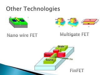
![• The carbon nanotube field effect transistor is a three
terminal device similar to the MOSFET.
• The semiconducting channel between the two
contacts called drain and source consists of the
nanotube.
• The channel is turned on/off electrostatically via the
third contact: gate
Planar Device Coaxial Device
Ref: [4]](https://image.slidesharecdn.com/cnfettechnology-140730040654-phpapp01/85/CNFET-Technology-14-320.jpg)
![Quasi 1-D (ballistic) transport of electrons and holes:
The electrons in a carbon nanotube are confined to the atomic
plane of the graphene. Since the structure of the CNT is quasi 1-
D, the electrons in the tube are constrained. The electrons can
only move along the axis of the tube.
Only forward and backward scattering is possible for the
electrons and holes in the nanotube.
Experimentally observed mean-free-path is of the order of 1um
(1,000 times the diameter of the tube) implies that carbon
nanotubes have ballistic transport capability. [4]](https://image.slidesharecdn.com/cnfettechnology-140730040654-phpapp01/85/CNFET-Technology-16-320.jpg)
![High Drive Current/Large Transconductance:
For the p-CNTFET, the on-current per unit ~1500 μA/μm at a gate
overdrive of 0.6V. This value is considerably higher than the ~500
μA/μm for a p-MOSFET at a gate overdrive of 0.6V.[14]
The maximum transconductance (dI/dVg) is observed to be 20uA/V at
Vg = -0.9. This, as compared to a typical MOSFET, is a significantly
better current generation by the device. [3]
Ref: [8]
Fig. Simulated I-V
characteristics
of the CNFET [8]](https://image.slidesharecdn.com/cnfettechnology-140730040654-phpapp01/85/CNFET-Technology-17-320.jpg)
![High temperature resilience/ Strong covalent bond:
The atoms within a carbon nanotube molecule bond covalently in
hexagonal rings, and this graphite-like structure has great
strength and stability.
Electrically, this helps in significantly reducing electromigration,
thereby allowing high current operation. [4]
Furthermore, carbon nanotubes conduct heat nearly as well as
diamond, so extremely high device-packing densities should be
possible [4]
Apart from these the CNFET has low intrinsic
capacitance and near ideal sub-threshold
slope. [2]](https://image.slidesharecdn.com/cnfettechnology-140730040654-phpapp01/85/CNFET-Technology-18-320.jpg)
![ A 3 :1 (PMOS:NMOS) ratio is used when designing an inverter.
For the CNFET, a 1:1 (pFET:nFET) ratio is used because the nFET and the
pFET have almost the same current driving capability with same transistor
geometry [12]
The PDP and the maximum leakage power of the 32nm CNFET are about
100 times and 75 times lower than for the 32nm MOSFET.
Ref: [13]
Inverter Char at
32nm](https://image.slidesharecdn.com/cnfettechnology-140730040654-phpapp01/85/CNFET-Technology-19-320.jpg)
![[1] Rabaey, J.M., Chandrakasan, A. , Nikolic, B., Digital Integrated Circuits Second Edition, 2002,
Prentice-Hall
[2] Ale, I., Hasan, M., Islam A. , Abbasi, S.A., “Optimized Design of a 32-nm CNFET-Based Low-
Power Ultra wideband CCII” IEEE Transactions On Nanotechnology, vol. 11, no. 6, pp. 1100-1108,
Nov. 2012
[3] P. L. McEuen, M. S. Fuhrer, and P. Hongkun, “Single-walled carbon nanotube electronics” IEEE
Transactions on Nanotechnology., vol. 1, no. 1, pp. 78–85, Mar. 2002
[4] Leonardo de Camargo e Castro, (2006) Modelling of Carbon Nanotube Field-Effect Transistor,
(Doctoral Dissertation), University of British Columbia
[5] Deng, J. (2007) Device Modelling And Circuit Performance Evaluation For Nanoscale Devices:
Silicon Technology Beyond 45 Nm Node And Carbon Nanotube Field Effect Transistors (Doctoral
Dissertation), Stanford University.
[6] Cho G, Kim Y-B, and Lombardi F: “Assessment of CNTFET based circuit performance and
robustness to PVT variations”. In Proceedings of the MWSCAS '09 52nd IEEE International
Midwest Symposium on Circuits and Systems: August 2–5: Cancun. New York: IEEE 2009,
2009:1106–1109.
[7] Moradinasab, Mahdi. Fathipour, Morteza. “High Performance SRAM based on CNFET”,
Ultimate Integration of Silicon, 2009. Pp.317-320, Mar. 2009](https://image.slidesharecdn.com/cnfettechnology-140730040654-phpapp01/85/CNFET-Technology-21-320.jpg)
![[8] A. Javey, J. Guo, D. B. Farmer, Q. Wang, E. Yenilmez, R. G. Gordon, M. Lundstrom, and H.
Dai, “Self-aligned ballistic molecular transistors and electrically parallel nanotube arrays,” Nano
Lett., vol. 4, no. 7, pp. 1319–1322, 2004.
[9] Murrae J. Bowden, “Moore’s Law and the Technology S-Curve” Current Issues in Technology
Management, winter 2004 Issue 1 Volume 8.
[10] Semiconductor Industry Association. (2005). International Technology Roadmap for
Semiconductors-2005, Update: Overview and Summaries, [Online]. Available:
http:ww.itrs.net/Links/2005, ITRS/Home 2005.htm
[11] D. J. Frank, R. H. Dennard, E. Nowak, P. M. Solomon, Y. Taur, and H. S. P.Wong, “Device
scaling limits of SiMOSFETS and their application dependencies,” in Proc. IEEE, vol. 89, no. 3,
pp. 259–288, Mar. 2001.
[12] J. Deng, and H.-S. P. Wong, "A Circuit-Compatible SPICE model for Enhancement Mode
Carbon Nanotube Field Effect Transistors," Proc. Intl. Conf. Simulation of Semiconductor
Processes and Devices, pp. 166-169, Sept., 2006
[13] Geunho Cho, Yong-Bin Kim, Fabrizio Lombardi , “Assessment of CNTFET Based Circuit
Performance and Robustness to PVT Variations” Circuits and Systems, 2009. MWSCAS '09. 52nd
IEEE International Midwest Symposium pp. 1106 – 1109
[14] S. Thompson, et al., IEDM Tech Digest, p. 257 (2001).](https://image.slidesharecdn.com/cnfettechnology-140730040654-phpapp01/85/CNFET-Technology-22-320.jpg)


The document summarizes carbon nanotube field effect transistors (CNFETs). It discusses how CNFETs offer advantages over traditional MOSFETs such as ballistic transport, high drive current, temperature resilience, and low capacitance. However, large-scale manufacturing of CNFETs poses challenges and circuit performance can only be estimated through simulations currently. The document also describes the structure, properties, types and performance of CNFETs. It analyzes how CNFET design can overcome issues facing MOSFET scaling like leakage and process variation.


