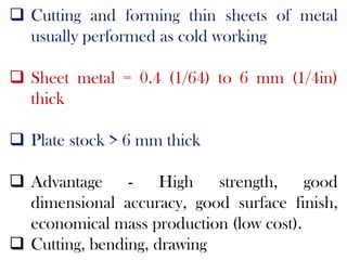
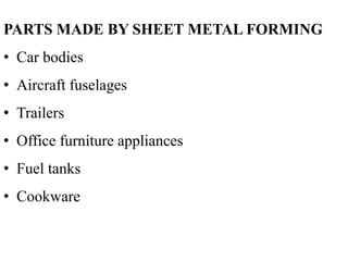
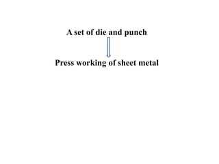
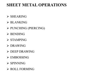
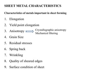
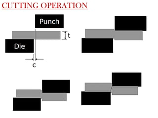
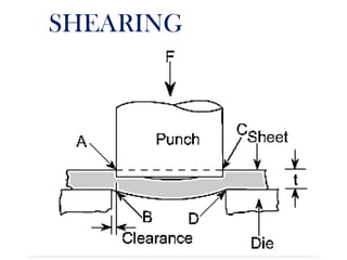
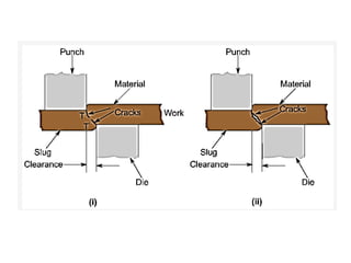
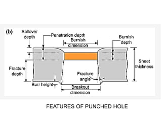
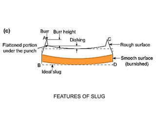
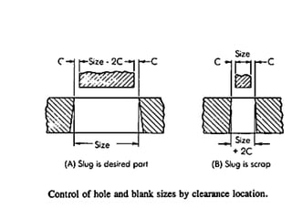
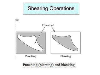
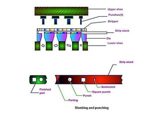
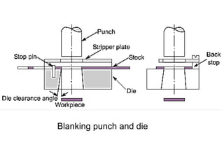
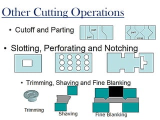
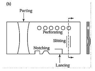
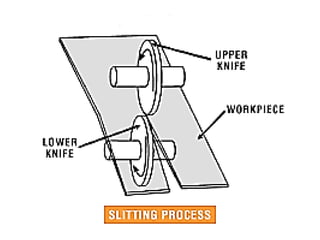
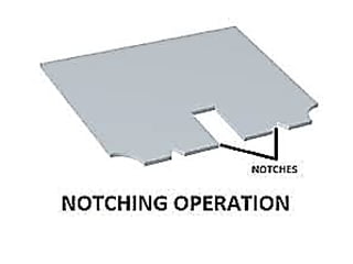
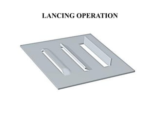
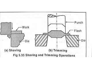
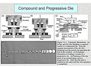
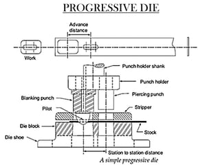
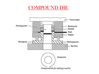
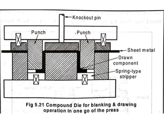
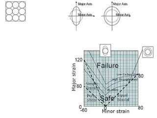
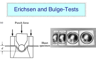
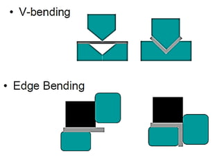
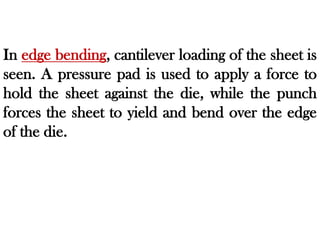
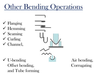
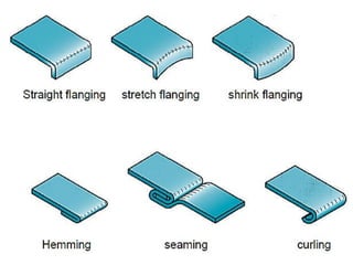
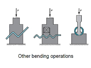
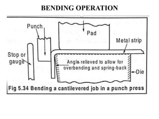
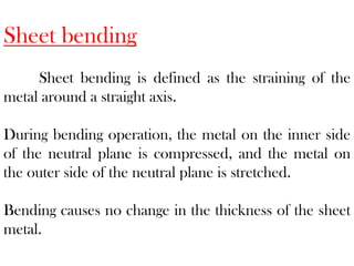
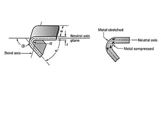
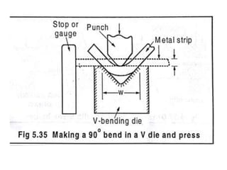
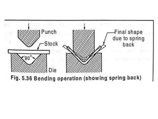
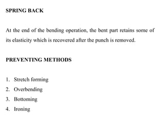
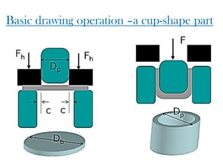
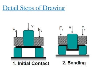
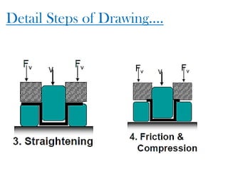
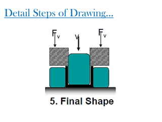
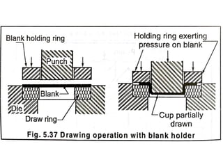
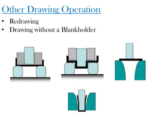
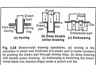
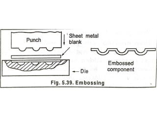
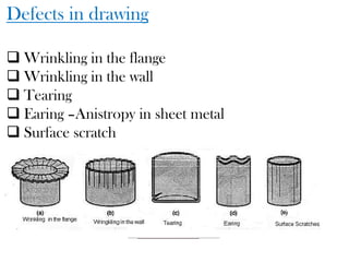
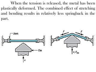
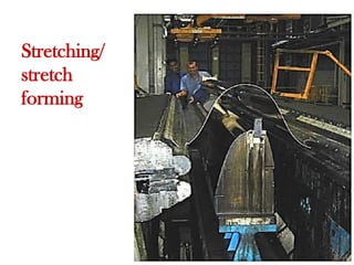
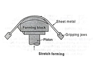
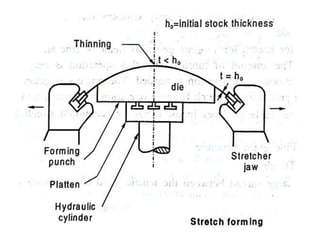
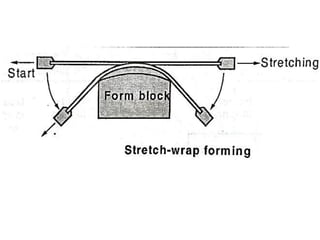
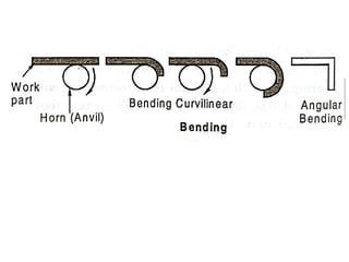
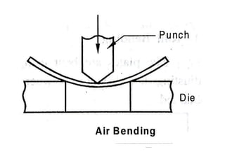
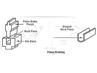
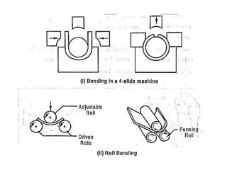
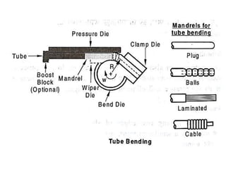
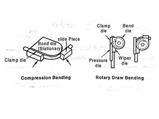
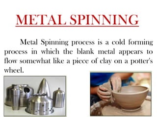
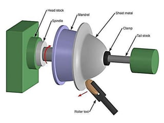
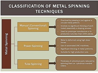
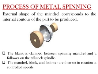
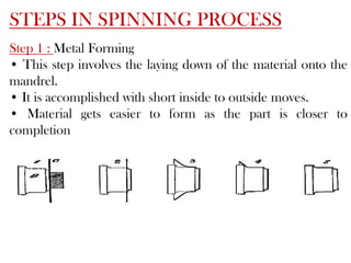
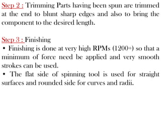
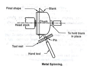
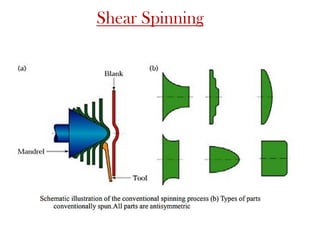
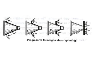
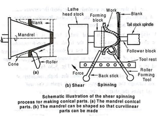
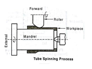
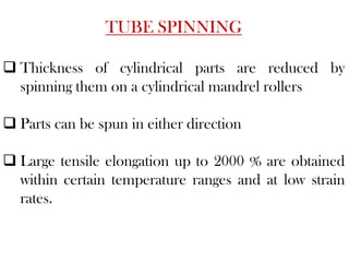
MODULE 5
SHEET METAL OPERATIONS
SHEET METALWORKING
 Cutting and forming thin sheets of metal
usually performed as cold working
 Sheet metal = 0.4 (1/64) to 6 mm (1/4in)
thick
 Plate stock > 6 mm thick
 Advantage - High strength, good
dimensional accuracy, good surface finish,
economical mass production (low cost).
 Cutting, bending, drawing
PARTS MADE BY SHEET METAL FORMING
• Car bodies
• Aircraft fuselages
• Trailers
• Office furniture appliances
• Fuel tanks
• Cookware
Sheet Metalworking Terminology
“Punch-and-die”Tooling to perform cutting,
bending, and drawing
“Stamping press” Machine tool that performs
most sheet metal operations
“Stampings”Sheet metal products
A set of die and punch
Press working of sheet metal
SHEET METAL OPERATIONS
 SHEARING
 BLANKING
 PUNCHING (PIERCING)
 BENDING
 STAMPING
 DRAWING
 DEEP DRAWING
 EMBOSSING
 SPINNING
 ROLL FORMING
SHEET METAL CHARACTERISTICS
Characteristics of metals important in sheet forming
1. Elongation
2. Yield point elongation
3. Anisotropy
4. Grain Size
5. Residual stresses
6. Spring back
7. Wrinkling
8. Quality of sheared edges
9. Surface condition of sheet
Crystallographic anisotropy
Mechanical fibering
Cutting Operation
•Shearing - using a machine called power shear or
square shear.
•Blanking – shearing a closed outline (desired part
called blank)
•Punching – sheared part is slag (or scrap) and
remaining stock is a desired part
CUTTING OPERATION
SHEARING
Analysis
Clearance -4-8% but sometime 1% of thickness
Too small –fracture does not occur requiring more force.
Too large –Get pinched and cause an excessive burr
Clearance: c=a*t
Metal group a
 1100S and 5052S aluminum alloys, all tempers 0.045
2024ST and 6061ST aluminum alloys;
 brass, soft cold rolled steel, soft stainless steel 0.060
 Cold rolled steel, half hard; stainless steel, half hard
and full hard 0.075
Factors affecting shearing operation
• Shape and material of the punch
• Die, speed of punching, lubrication
• Clearance between punch & die
Die, blank and punch size
 For a round blank,
Blank punch diameter=Db-2c
Blank die diameter = Db
 For a round hole,
Hole punch diameter=Dh
Hole die diameter = Dh+2c
 Angular clearance of 0.25°to 1.5°
 Cutting forces: F=S×t×L=0.7×TS×t×L
where S= Shear strength
t=thickness
L=length of cutting edge
TS =Ultimate tensile strength
STAGES IN SHEARING ACTION
1. Plastic Deformation
2. Fracture
3. Shear
FEATURES OF PUNCHED HOLE
FEATURES OF SLUG
Blanking punch and die
Other Cutting Operations
LANCING OPERATION
Maximum force, P required to be exerted by the
punch to shear out a blank from the sheet can be
estimated as
P = t.L.τ
t – Sheet thickness
L – Total length sheared
τ - Shear strength of the sheet material
Shearing force, SF = 0.02 Lt
SF – Shearing force in KN
L – Length of cut in mm
t – Thickness of material in mm
Clearance between die and punch,
c = 0.003t.τ
τ
PROGRESSIVE AND COMPOUND DIES
PROGRESSIVE DIE
COMPOUND DIE
Forming-Limit Diagram
A grid pattern of circles, typically 2.5 to 5mm in
diameter, produced by electrochemical or
photoprinting.
After drawing, the circles are observed for failure.
The major strain is on the major direction and
magnitude of strain
Bending Operations
In V-bending, the sheet metal is bent between a
V-shaped punch and die set up. The included
angles range from very obtuse to very acute
values.
In edge bending, cantilever loading of the sheet is
seen. A pressure pad is used to apply a force to
hold the sheet against the die, while the punch
forces the sheet to yield and bend over the edge
of the die.
Other Bending Operations
 Flanging
 Hemming
 Seaming
 Curling
 Channel,
 U-bending Air bending,
Offset bending, Corrugating
and Tube forming
BENDING OPERATION
Sheet bending
Sheet bending is defined as the straining of the
metal around a straight axis.
During bending operation, the metal on the inner side
of the neutral plane is compressed, and the metal on
the outer side of the neutral plane is stretched.
Bending causes no change in the thickness of the sheet
metal.
SPRING BACK
At the end of the bending operation, the bent part retains some of
its elasticity which is recovered after the punch is removed.
PREVENTING METHODS
1. Stretch forming
2. Overbending
3. Bottoming
4. Ironing
Drawing
Basic drawing operation –a cup-shape part
Detail Steps of Drawing
Detail Steps of Drawing….
Detail Steps of Drawing…
Other Drawing Operation
• Redrawing
• Drawing without a Blankholder
Defects in drawing
 Wrinkling in the flange
 Wrinkling in the wall
 Tearing
 Earing –Anistropy in sheet metal
 Surface scratch
 Wrinkling in flange and cup wall: This is like ups and downs or
waviness that is developed on the flange. If the flange is drawn
into the die hole, it will be retained in cup wall region.
 Tearing: It is a crack in the cup, near the base, happening due to
high tensile stresses causing thinning and failure of the metal at
this place. This can also occur due to sharp die corner.
 Earing: The height of the walls of drawn cups have peaks and
valleys called as earing. There may be more than four ears.
Earing results from planar anisotropy (ΔR), and ear height and
angular position correlate well with the angular variation of R.
 Surface scratches: Usage of rough punch, dies and poor
lubrication cause scratches in a drawn cup.
Stretching/stretch forming
Stretch forming is a sheet metal forming process
in which the sheet metal is intentionally stretched and
simultaneously bent to have the shape change.
Sheet is held by jaws or drawbeads at both the ends and
then stretched by punch, such that the sheet is stressed
above yield strength.
When the tension is released, the metal has been
plastically deformed. The combined effect of stretching
and bending results in relatively less springback in the
part.
Stretching/
stretch
forming
METAL SPINNING
Metal Spinning process is a cold forming
process in which the blank metal appears to
flow somewhat like a piece of clay on a potter's
wheel.
PROCESS OF METAL SPINNING
External shape of the mandrel corresponds to the
internal contour of the part to be produced.
 The blank is clamped between spinning mandrel and a
follower on the tailstock spindle.
 The mandrel, blank, and follower are then set in rotation at
controlled speeds.
STEPS IN SPINNING PROCESS
Step 1 : Metal Forming
• This step involves the laying down of the material onto the
mandrel.
• It is accomplished with short inside to outside moves.
• Material gets easier to form as the part is closer to
completion
Step 2 : Trimming Parts having been spun are trimmed
at the end to blunt sharp edges and also to bring the
component to the desired length.
Step 3 : Finishing
• Finishing is done at very high RPMs (1200+) so that a
minimum of force need be applied and very smooth
strokes can be used.
• The flat side of spinning tool is used for straight
surfaces and rounded side for curves and radii.
Shear Spinning
TUBE SPINNING
 Thickness of cylindrical parts are reduced by
spinning them on a cylindrical mandrel rollers
 Parts can be spun in either direction
 Large tensile elongation up to 2000 % are obtained
within certain temperature ranges and at low strain
rates.
COMPARISON WITH OTHER FORMING
PROCESSES
 Low tooling cost compared to other forming
techniques.
 Conventional spinning also wastes a considerably
smaller amount of material than other methods .
 The standard method of press forming the part
requires many steps, as opposed to only three steps
for spinning.
Rubber forming
In bending and embossing of sheet metal,
the female die is replaced with rubber pad
 Rubber pad forming (RPF) is
a metalworking process where sheet metal is
pressed between a die and a rubber block,
made of polyurethane.
 Under pressure, the rubber and sheet metal
are driven into the die and conform to its
shape, forming the part.
Rubber pads can have a general purpose shape,
like a membrane. Alternatively, they can be machined
in the shape of die or punch.

Sheet Metal Mfg Tech.pdf

  • 1.
  • 2.
  • 3.
     Cutting andforming thin sheets of metal usually performed as cold working  Sheet metal = 0.4 (1/64) to 6 mm (1/4in) thick  Plate stock > 6 mm thick  Advantage - High strength, good dimensional accuracy, good surface finish, economical mass production (low cost).  Cutting, bending, drawing
  • 4.
    PARTS MADE BYSHEET METAL FORMING • Car bodies • Aircraft fuselages • Trailers • Office furniture appliances • Fuel tanks • Cookware
  • 5.
    Sheet Metalworking Terminology “Punch-and-die”Toolingto perform cutting, bending, and drawing “Stamping press” Machine tool that performs most sheet metal operations “Stampings”Sheet metal products
  • 6.
    A set ofdie and punch Press working of sheet metal
  • 7.
    SHEET METAL OPERATIONS SHEARING  BLANKING  PUNCHING (PIERCING)  BENDING  STAMPING  DRAWING  DEEP DRAWING  EMBOSSING  SPINNING  ROLL FORMING
  • 8.
    SHEET METAL CHARACTERISTICS Characteristicsof metals important in sheet forming 1. Elongation 2. Yield point elongation 3. Anisotropy 4. Grain Size 5. Residual stresses 6. Spring back 7. Wrinkling 8. Quality of sheared edges 9. Surface condition of sheet Crystallographic anisotropy Mechanical fibering
  • 9.
    Cutting Operation •Shearing -using a machine called power shear or square shear. •Blanking – shearing a closed outline (desired part called blank) •Punching – sheared part is slag (or scrap) and remaining stock is a desired part
  • 10.
  • 12.
  • 13.
    Analysis Clearance -4-8% butsometime 1% of thickness Too small –fracture does not occur requiring more force. Too large –Get pinched and cause an excessive burr Clearance: c=a*t Metal group a  1100S and 5052S aluminum alloys, all tempers 0.045 2024ST and 6061ST aluminum alloys;  brass, soft cold rolled steel, soft stainless steel 0.060  Cold rolled steel, half hard; stainless steel, half hard and full hard 0.075
  • 14.
    Factors affecting shearingoperation • Shape and material of the punch • Die, speed of punching, lubrication • Clearance between punch & die
  • 15.
    Die, blank andpunch size  For a round blank, Blank punch diameter=Db-2c Blank die diameter = Db  For a round hole, Hole punch diameter=Dh Hole die diameter = Dh+2c  Angular clearance of 0.25°to 1.5°  Cutting forces: F=S×t×L=0.7×TS×t×L where S= Shear strength t=thickness L=length of cutting edge TS =Ultimate tensile strength
  • 16.
    STAGES IN SHEARINGACTION 1. Plastic Deformation 2. Fracture 3. Shear
  • 18.
  • 19.
  • 23.
  • 24.
  • 28.
  • 29.
    Maximum force, Prequired to be exerted by the punch to shear out a blank from the sheet can be estimated as P = t.L.τ t – Sheet thickness L – Total length sheared τ - Shear strength of the sheet material
  • 30.
    Shearing force, SF= 0.02 Lt SF – Shearing force in KN L – Length of cut in mm t – Thickness of material in mm
  • 31.
    Clearance between dieand punch, c = 0.003t.τ
  • 32.
  • 34.
  • 36.
  • 37.
  • 40.
    Forming-Limit Diagram A gridpattern of circles, typically 2.5 to 5mm in diameter, produced by electrochemical or photoprinting. After drawing, the circles are observed for failure. The major strain is on the major direction and magnitude of strain
  • 43.
  • 45.
    In V-bending, thesheet metal is bent between a V-shaped punch and die set up. The included angles range from very obtuse to very acute values.
  • 46.
    In edge bending,cantilever loading of the sheet is seen. A pressure pad is used to apply a force to hold the sheet against the die, while the punch forces the sheet to yield and bend over the edge of the die.
  • 47.
    Other Bending Operations Flanging  Hemming  Seaming  Curling  Channel,  U-bending Air bending, Offset bending, Corrugating and Tube forming
  • 50.
  • 51.
    Sheet bending Sheet bendingis defined as the straining of the metal around a straight axis. During bending operation, the metal on the inner side of the neutral plane is compressed, and the metal on the outer side of the neutral plane is stretched. Bending causes no change in the thickness of the sheet metal.
  • 55.
    SPRING BACK At theend of the bending operation, the bent part retains some of its elasticity which is recovered after the punch is removed. PREVENTING METHODS 1. Stretch forming 2. Overbending 3. Bottoming 4. Ironing
  • 56.
  • 57.
    Basic drawing operation–a cup-shape part
  • 58.
  • 59.
    Detail Steps ofDrawing….
  • 60.
    Detail Steps ofDrawing…
  • 62.
    Other Drawing Operation •Redrawing • Drawing without a Blankholder
  • 65.
    Defects in drawing Wrinkling in the flange  Wrinkling in the wall  Tearing  Earing –Anistropy in sheet metal  Surface scratch
  • 66.
     Wrinkling inflange and cup wall: This is like ups and downs or waviness that is developed on the flange. If the flange is drawn into the die hole, it will be retained in cup wall region.  Tearing: It is a crack in the cup, near the base, happening due to high tensile stresses causing thinning and failure of the metal at this place. This can also occur due to sharp die corner.  Earing: The height of the walls of drawn cups have peaks and valleys called as earing. There may be more than four ears. Earing results from planar anisotropy (ΔR), and ear height and angular position correlate well with the angular variation of R.  Surface scratches: Usage of rough punch, dies and poor lubrication cause scratches in a drawn cup.
  • 67.
    Stretching/stretch forming Stretch formingis a sheet metal forming process in which the sheet metal is intentionally stretched and simultaneously bent to have the shape change. Sheet is held by jaws or drawbeads at both the ends and then stretched by punch, such that the sheet is stressed above yield strength.
  • 68.
    When the tensionis released, the metal has been plastically deformed. The combined effect of stretching and bending results in relatively less springback in the part.
  • 69.
  • 79.
    METAL SPINNING Metal Spinningprocess is a cold forming process in which the blank metal appears to flow somewhat like a piece of clay on a potter's wheel.
  • 82.
    PROCESS OF METALSPINNING External shape of the mandrel corresponds to the internal contour of the part to be produced.  The blank is clamped between spinning mandrel and a follower on the tailstock spindle.  The mandrel, blank, and follower are then set in rotation at controlled speeds.
  • 83.
    STEPS IN SPINNINGPROCESS Step 1 : Metal Forming • This step involves the laying down of the material onto the mandrel. • It is accomplished with short inside to outside moves. • Material gets easier to form as the part is closer to completion
  • 84.
    Step 2 :Trimming Parts having been spun are trimmed at the end to blunt sharp edges and also to bring the component to the desired length. Step 3 : Finishing • Finishing is done at very high RPMs (1200+) so that a minimum of force need be applied and very smooth strokes can be used. • The flat side of spinning tool is used for straight surfaces and rounded side for curves and radii.
  • 86.
  • 90.
    TUBE SPINNING  Thicknessof cylindrical parts are reduced by spinning them on a cylindrical mandrel rollers  Parts can be spun in either direction  Large tensile elongation up to 2000 % are obtained within certain temperature ranges and at low strain rates.
  • 91.
    COMPARISON WITH OTHERFORMING PROCESSES  Low tooling cost compared to other forming techniques.  Conventional spinning also wastes a considerably smaller amount of material than other methods .  The standard method of press forming the part requires many steps, as opposed to only three steps for spinning.
  • 92.
    Rubber forming In bendingand embossing of sheet metal, the female die is replaced with rubber pad  Rubber pad forming (RPF) is a metalworking process where sheet metal is pressed between a die and a rubber block, made of polyurethane.  Under pressure, the rubber and sheet metal are driven into the die and conform to its shape, forming the part.
  • 93.
    Rubber pads canhave a general purpose shape, like a membrane. Alternatively, they can be machined in the shape of die or punch.