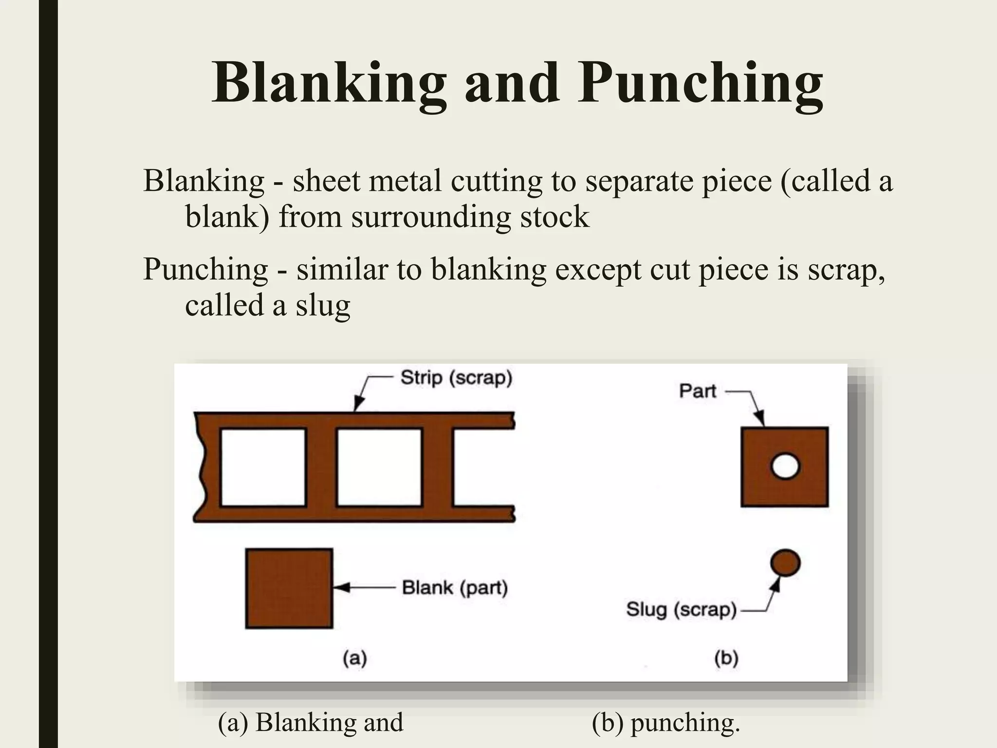
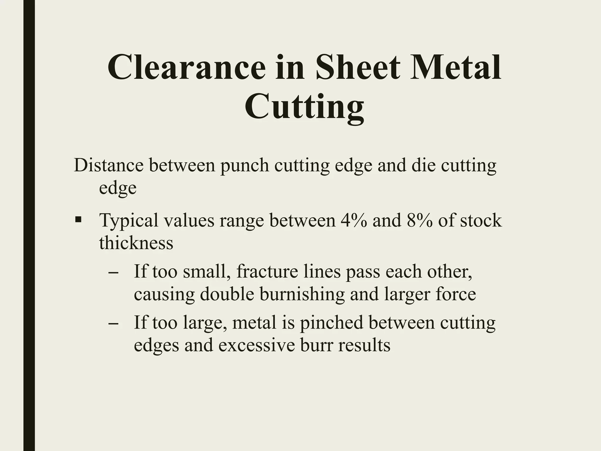
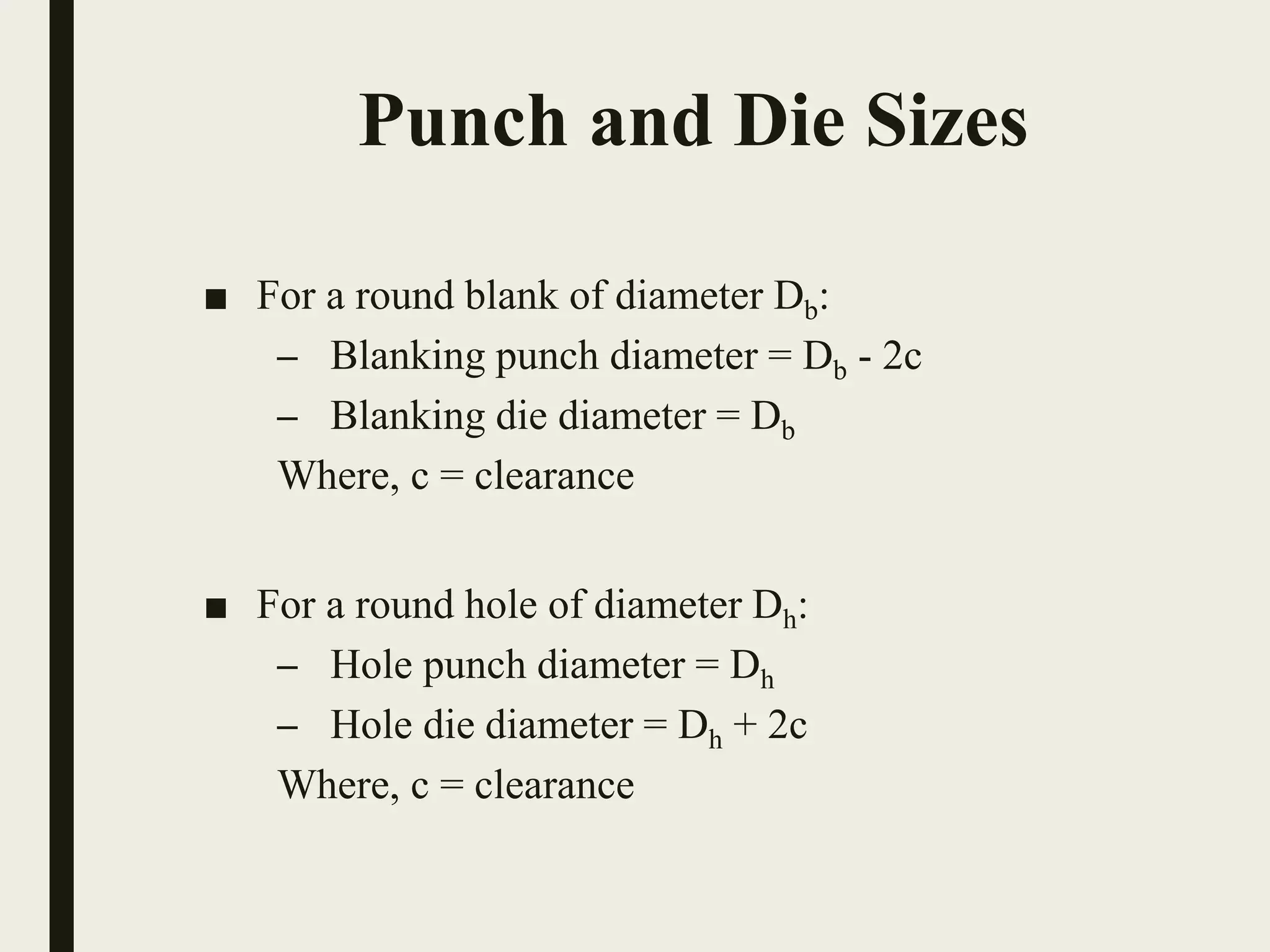
SHEET METAL
FORMING
PROCESSES
Prepared By:-
• Varmora Raxit V.
Sheet Metal Working
1. Cutting Operations
2. Bending Operations
3. Drawing
4. Other Sheet Metal Forming Operations
5. Dies and Presses for Sheet Metal Processes
6. Sheet Metal Operations Not Performed on Presses
Sheet Metal Working
Defined
Cutting and forming operations performed on relatively
thin sheets of metal
 Thickness of sheet metal = 0.4 mm (1/64 in) to 6 mm
(1/4 in)
 Operations usually performed as cold working
Sheet and Plate Metal
Products
■ Sheet and plate metal parts for consumer and
industrial products such as
– Automobiles and trucks
– Airplanes
– Railway cars and locomotives
– Farm and construction equipment
– Small and large appliances
– Office furniture
– Computers and office equipment
Advantages of Sheet Metal
Parts
 High strength
 Good dimensional accuracy
 Good surface finish
 Relatively low cost
 Economical mass production for large quantities
Sheet Metalworking
Terminology
 Punch-and-die - tooling to perform cutting, bending,
and drawing
 Stamping press - machine tool that performs most
sheet metal operations
 Stampings - sheet metal products
Basic Types of Sheet Metal
Processes
1. Cutting
– Shearing to separate large sheets
– Blanking to cut part perimeters out of sheet metal
– Punching to make holes in sheet metal
2. Bending
– Straining sheet around a straight axis
3. Drawing
– Forming of sheet into convex or concave shapes
Sheet Metal Cutting
Shearing of sheet metal between two cutting edges:
(1) Just before the punch contacts work
(2) Punch begins to push into work, causing plastic deformation
Shearing of sheet metal between two cutting edges:
(3) Punch compresses and penetrates into work causing a smooth cut surface
(4) Fracture is initiated at the opposing cutting edges which separates the sheet.
Sheet Metal Cutting
Shearing
Sheet metal cutting operation along a straight line between
two cutting edges
 Typically used to cut large sheets
Shearing operation: (a) side view of the shearing operation; (b) front
view of power shears equipped with inclined upper cutting blade.
Blanking and Punching
Blanking - sheet metal cutting to separate piece (called a
blank) from surrounding stock
Punching - similar to blanking except cut piece is scrap,
called a slug
(a) Blanking and (b) punching.
Clearance in Sheet Metal
Cutting
Distance between punch cutting edge and die cutting
edge
 Typical values range between 4% and 8% of stock
thickness
– If too small, fracture lines pass each other,
causing double burnishing and larger force
– If too large, metal is pinched between cutting
edges and excessive burr results
Clearance in Sheet Metal
Cutting
 Recommended clearance is calculated by:
c = at
where,
c = clearance;
a = allowance; and
t = stock thickness
 Allowance a is determined according to type of metal
Punch and Die Sizes
■ For a round blank of diameter Db:
– Blanking punch diameter = Db - 2c
– Blanking die diameter = Db
Where, c = clearance
■ For a round hole of diameter Dh:
– Hole punch diameter = Dh
– Hole die diameter = Dh + 2c
Where, c = clearance
Die size determines blank size Db;
punch size determines hole size Dh.;
c = clearance
Punch and Die Sizes
Purpose: allows slug or blank to drop through die
■ Typical values: 0.25 to 1.5 on each side
Angular Clearance
Cutting Forces
Important for determining press size (tonnage)
F = S t L
where
S = shear strength of metal;
t = stock thickness, and
L = length of cut edge
Metal on inside of neutral plane is compressed, while metal on
outside of neutral plane is stretched
both compression and tensile elongation of the metal
occur in bending.
Sheet Metal Bending
 For low production
 Performed on a press brake
 V-dies are simple and inexpensive
V-Bending
 For high production
 Pressure pad required
 Dies are more complicated and costly
Edge Bending
Bend Allowance Formula
Where,
Ab = bend allowance;
 = bend angle;
R= bend radius;
t = stock thickness; and
Kba is factor to estimate stretching
 If R < 2t, Kba = 0.33
 If R  2t, Kba = 0.50
)tKR(A bab +
360
2=
α
π
Spring back
Increase in included angle of bent part relative to included
angle of forming tool after tool is removed
■ Reason for spring back:
– When bending pressure is removed, elastic energy
remains in bent part, causing it to recover partially
toward its original shape
Spring back in bending is seen as a decrease in bend angle and an increase in
bend radius: (1) during bending, the work is forced to take radius Rb and
included angle b' of the bending tool, (2) after punch is removed, the work
springs back to radius R and angle ‘.
Spring back
 
Bending Force
Maximum bending force estimated as follows:
Where, F = bending force;
TS = tensile strength of sheet metal;
w = part width in direction of bend axis; and
t = stock thickness.
For V- bending,
Kbf = 1.33; for edge bending,
Kbf = 0.33
D
TSwtK
F bf
2

Drawing
Sheet metal forming to make cup-shaped, box-shaped, or
other complex-curved, hollow-shaped parts
■ Sheet metal blank is positioned over die cavity and
then punch pushes metal into opening
■ Products: beverage cans, ammunition shells,
automobile body panels
■ Also known as deep drawing (to distinguish it from
wire and bar drawing)
Drawing
■ Clearance in Drawing
Sides of punch and die separated by a clearance c given by:
c = 1.1 t
where, t = stock thickness
 In other words, clearance is about 10% greater than stock
thickness
■ Makes wall thickness of cylindrical cup more uniform
Ironing to achieve more uniform wall thickness in a drawn cup:
(1) start of process; (2) during process. Note thinning and
elongation of walls.
Ironing
Creates indentations in sheet, such as raised (or indented)
lettering or strengthening ribs.
Embossing: (a) cross-section of punch and die configuration during
pressing; (b) finished part with embossed ribs.
Embossing
Guerin process: (1) before and (2) after. Symbols v and F indicate
motion and applied force respectively.
Guerin Process
Dies for Sheet Metal
Processes
Punch and Die Components
Compound Die
(a) Progressive die;
(b) associated strip development
Progressive Die
Stamping Press
Power and Drive Systems
■ Hydraulic presses - use a large piston and cylinder to
drive the ram
– Longer ram stroke than mechanical types
– Suited to deep drawing
– Slower than mechanical drives
■ Mechanical presses – convert rotation of motor to
linear motion of ram
– High forces at bottom of stroke
– Suited to blanking and punching
Sheet metal is stretched and simultaneously bent to achieve
shape change
Stretch forming: (1) start of process; (2) form die is pressed into the
work with force Fdie, causing it to be stretched and bent over the
form. F = stretching force.
Stretch Forming
Large metal sheets and plates are formed into curved
sections using rolls
Roll Bending
Continuous bending process in which opposing rolls produce
long sections of formed shapes from coil or strip stock
Roll forming of a
continuous
channel section:
(1) straight rolls,
(2) partial form,
(3) final form.
Roll Forming
Spinning
Metal forming process in which an axially symmetric
part is gradually shaped over a rotating mandrel using
a rounded tool or roller
■Three types: 1.Conventional spinning
2.Shear spinning
3.Tube spinning
Conventional spinning: (1) setup at start of process; (2) during spinning;
and (3) completion of process.
Sheet metal working

Sheet metal working

  • 1.
  • 2.
  • 3.
    Sheet Metal Working 1.Cutting Operations 2. Bending Operations 3. Drawing 4. Other Sheet Metal Forming Operations 5. Dies and Presses for Sheet Metal Processes 6. Sheet Metal Operations Not Performed on Presses
  • 4.
    Sheet Metal Working Defined Cuttingand forming operations performed on relatively thin sheets of metal  Thickness of sheet metal = 0.4 mm (1/64 in) to 6 mm (1/4 in)  Operations usually performed as cold working
  • 5.
    Sheet and PlateMetal Products ■ Sheet and plate metal parts for consumer and industrial products such as – Automobiles and trucks – Airplanes – Railway cars and locomotives – Farm and construction equipment – Small and large appliances – Office furniture – Computers and office equipment
  • 6.
    Advantages of SheetMetal Parts  High strength  Good dimensional accuracy  Good surface finish  Relatively low cost  Economical mass production for large quantities
  • 7.
    Sheet Metalworking Terminology  Punch-and-die- tooling to perform cutting, bending, and drawing  Stamping press - machine tool that performs most sheet metal operations  Stampings - sheet metal products
  • 8.
    Basic Types ofSheet Metal Processes 1. Cutting – Shearing to separate large sheets – Blanking to cut part perimeters out of sheet metal – Punching to make holes in sheet metal 2. Bending – Straining sheet around a straight axis 3. Drawing – Forming of sheet into convex or concave shapes
  • 9.
    Sheet Metal Cutting Shearingof sheet metal between two cutting edges: (1) Just before the punch contacts work (2) Punch begins to push into work, causing plastic deformation
  • 10.
    Shearing of sheetmetal between two cutting edges: (3) Punch compresses and penetrates into work causing a smooth cut surface (4) Fracture is initiated at the opposing cutting edges which separates the sheet. Sheet Metal Cutting
  • 11.
    Shearing Sheet metal cuttingoperation along a straight line between two cutting edges  Typically used to cut large sheets Shearing operation: (a) side view of the shearing operation; (b) front view of power shears equipped with inclined upper cutting blade.
  • 12.
    Blanking and Punching Blanking- sheet metal cutting to separate piece (called a blank) from surrounding stock Punching - similar to blanking except cut piece is scrap, called a slug (a) Blanking and (b) punching.
  • 13.
    Clearance in SheetMetal Cutting Distance between punch cutting edge and die cutting edge  Typical values range between 4% and 8% of stock thickness – If too small, fracture lines pass each other, causing double burnishing and larger force – If too large, metal is pinched between cutting edges and excessive burr results
  • 14.
    Clearance in SheetMetal Cutting  Recommended clearance is calculated by: c = at where, c = clearance; a = allowance; and t = stock thickness  Allowance a is determined according to type of metal
  • 15.
    Punch and DieSizes ■ For a round blank of diameter Db: – Blanking punch diameter = Db - 2c – Blanking die diameter = Db Where, c = clearance ■ For a round hole of diameter Dh: – Hole punch diameter = Dh – Hole die diameter = Dh + 2c Where, c = clearance
  • 16.
    Die size determinesblank size Db; punch size determines hole size Dh.; c = clearance Punch and Die Sizes
  • 17.
    Purpose: allows slugor blank to drop through die ■ Typical values: 0.25 to 1.5 on each side Angular Clearance
  • 18.
    Cutting Forces Important fordetermining press size (tonnage) F = S t L where S = shear strength of metal; t = stock thickness, and L = length of cut edge
  • 19.
    Metal on insideof neutral plane is compressed, while metal on outside of neutral plane is stretched both compression and tensile elongation of the metal occur in bending. Sheet Metal Bending
  • 20.
     For lowproduction  Performed on a press brake  V-dies are simple and inexpensive V-Bending
  • 21.
     For highproduction  Pressure pad required  Dies are more complicated and costly Edge Bending
  • 22.
    Bend Allowance Formula Where, Ab= bend allowance;  = bend angle; R= bend radius; t = stock thickness; and Kba is factor to estimate stretching  If R < 2t, Kba = 0.33  If R  2t, Kba = 0.50 )tKR(A bab + 360 2= α π
  • 23.
    Spring back Increase inincluded angle of bent part relative to included angle of forming tool after tool is removed ■ Reason for spring back: – When bending pressure is removed, elastic energy remains in bent part, causing it to recover partially toward its original shape
  • 24.
    Spring back inbending is seen as a decrease in bend angle and an increase in bend radius: (1) during bending, the work is forced to take radius Rb and included angle b' of the bending tool, (2) after punch is removed, the work springs back to radius R and angle ‘. Spring back  
  • 25.
    Bending Force Maximum bendingforce estimated as follows: Where, F = bending force; TS = tensile strength of sheet metal; w = part width in direction of bend axis; and t = stock thickness. For V- bending, Kbf = 1.33; for edge bending, Kbf = 0.33 D TSwtK F bf 2 
  • 26.
    Drawing Sheet metal formingto make cup-shaped, box-shaped, or other complex-curved, hollow-shaped parts ■ Sheet metal blank is positioned over die cavity and then punch pushes metal into opening ■ Products: beverage cans, ammunition shells, automobile body panels ■ Also known as deep drawing (to distinguish it from wire and bar drawing)
  • 27.
    Drawing ■ Clearance inDrawing Sides of punch and die separated by a clearance c given by: c = 1.1 t where, t = stock thickness  In other words, clearance is about 10% greater than stock thickness
  • 28.
    ■ Makes wallthickness of cylindrical cup more uniform Ironing to achieve more uniform wall thickness in a drawn cup: (1) start of process; (2) during process. Note thinning and elongation of walls. Ironing
  • 29.
    Creates indentations insheet, such as raised (or indented) lettering or strengthening ribs. Embossing: (a) cross-section of punch and die configuration during pressing; (b) finished part with embossed ribs. Embossing
  • 30.
    Guerin process: (1)before and (2) after. Symbols v and F indicate motion and applied force respectively. Guerin Process
  • 31.
    Dies for SheetMetal Processes Punch and Die Components
  • 32.
  • 33.
    (a) Progressive die; (b)associated strip development Progressive Die
  • 34.
  • 35.
    Power and DriveSystems ■ Hydraulic presses - use a large piston and cylinder to drive the ram – Longer ram stroke than mechanical types – Suited to deep drawing – Slower than mechanical drives ■ Mechanical presses – convert rotation of motor to linear motion of ram – High forces at bottom of stroke – Suited to blanking and punching
  • 36.
    Sheet metal isstretched and simultaneously bent to achieve shape change Stretch forming: (1) start of process; (2) form die is pressed into the work with force Fdie, causing it to be stretched and bent over the form. F = stretching force. Stretch Forming
  • 37.
    Large metal sheetsand plates are formed into curved sections using rolls Roll Bending
  • 38.
    Continuous bending processin which opposing rolls produce long sections of formed shapes from coil or strip stock Roll forming of a continuous channel section: (1) straight rolls, (2) partial form, (3) final form. Roll Forming
  • 39.
    Spinning Metal forming processin which an axially symmetric part is gradually shaped over a rotating mandrel using a rounded tool or roller ■Three types: 1.Conventional spinning 2.Shear spinning 3.Tube spinning Conventional spinning: (1) setup at start of process; (2) during spinning; and (3) completion of process.