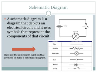
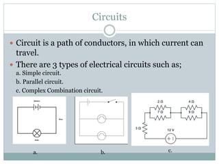
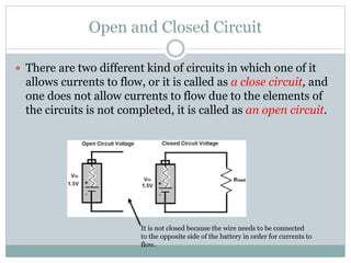
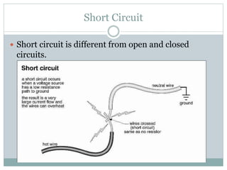
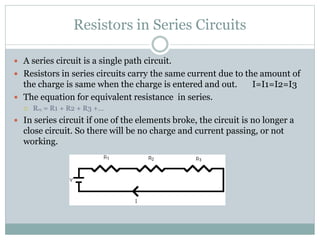
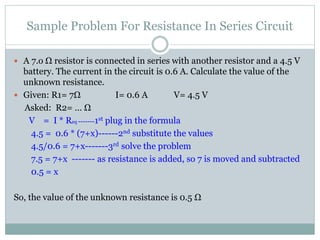
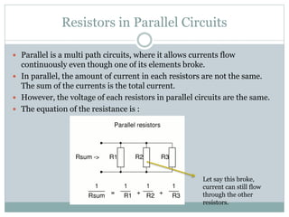
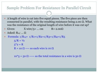
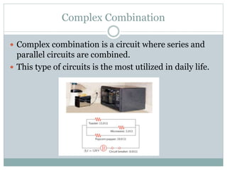
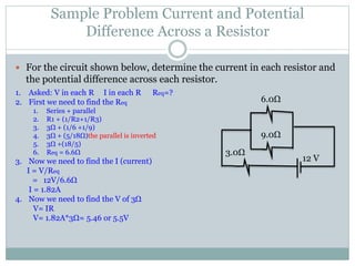
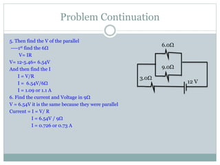
P A N D U E K O Y U D H O
1 1 P H Y S I C S
1 2 J A N U A R Y 2 0 1 5
P A N D U E K O Y U D H O
1. Schematic Diagram and
Circuits
Schematic Diagram
 A schematic diagram is a
diagram that depicts an
electrical circuit and it uses
symbols that represent the
components of that circuit.
Here are the component symbols that
are used to make a schematic diagram.
Circuits
 Circuit is a path of conductors, in which current can
travel.
 There are 3 types of electrical circuits such as;
a. Simple circuit.
b. Parallel circuit.
c. Complex Combination circuit.
a. b. c.
Open and Closed Circuit
 There are two different kind of circuits in which one of it
allows currents to flow, or it is called as a close circuit, and
one does not allow currents to flow due to the elements of
the circuits is not completed, it is called as an open circuit.
It is not closed because the wire needs to be connected
to the opposite side of the battery in order for currents to
flow.
Short Circuit
 Short circuit is different from open and closed
circuits.
Potential Difference
 Potential difference is the moves of charges from one terminal to the
other of the batteries. Batteries serve as a constant source of potential
difference in order to force the current to flow. As the charges flow, the
electrical potential energy is converted into other energy such as heat.
As the current flows between two points, every charge gains energy that
is equal to the difference of potential between them.
 The calculation is using the Ohm’s Law which is
V= IR
V is the potential difference
I is the current flowing
R is the resistance
Problem 
 If the potential difference across the bulb in a certain
flashlight is 3.0 V, what is the potential difference
across the combination of batteries used to power it?
 Answer:
 The potential across the bulb should be the same as across the
power supply so 3.0 V. It because the energy is dissipated
through heat mostly
P A N D U E K O D U D H O
2. Resistors in Series
or Parallel
Resistors in Series Circuits
 A series circuit is a single path circuit.
 Resistors in series circuits carry the same current due to the amount of
the charge is same when the charge is entered and out. I=I1=I2=I3
 The equation for equivalent resistance in series.
 Req = R1 + R2 + R3 +…
 In series circuit if one of the elements broke, the circuit is no longer a
close circuit. So there will be no charge and current passing, or not
working.
Sample Problem For Resistance In Series Circuit
 A 7.o Ω resistor is connected in series with another resistor and a 4.5 V
battery. The current in the circuit is 0.6 A. Calculate the value of the
unknown resistance.
 Given: R1= 7Ω I= 0.6 A V= 4.5 V
Asked: R2= … Ω
V = I * Req -------1st plug in the formula
4.5 = 0.6 * (7+x)------2nd substitute the values
4.5/0.6 = 7+x-------3rd solve the problem
7.5 = 7+x ------- as resistance is added, so 7 is moved and subtracted
0.5 = x
So, the value of the unknown resistance is 0.5 Ω
Resistors in Parallel Circuits
 Parallel is a multi path circuits, where it allows currents flow
continuously even though one of its elements broke.
 In parallel, the amount of current in each resistors are not the same.
The sum of the currents is the total current.
 However, the voltage of each resistors in parallel circuits are the same.
 The equation of the resistance is :
Let say this broke,
current can still flow
through the other
resistors.
Sample Problem For Resistance In Parallel Circuit
 A length of wire is cut into five equal pieces. The five piece are then
connected in parallel, with the resulting resistance being 2.00 Ω. What
was the resistance of the original length of wire before it was cut up?
 Given: X wire/5= … cm R= 2.00Ω
 Asked: Req: … Ω
 Formula: 1/Req= 1/R1+1/R2+1/R3+1/R4+1/R5
5/R = ½
5*2 = R
R = 10 Ω ---- so each wire is 10 Ω
10*5 = 50 Ω ----- so the total resistance in a wire is 50 Ω
P A N D U E K O Y U D H O
Complex Resistors
Combination
Complex Combination
 Complex combination is a circuit where series and
parallel circuits are combined.
 This type of circuits is the most utilized in daily life.
Sample Problem Complex Resistors Combination
 Find the equivalent resistance of the circuit shown in the figure below.
30V
18 Ω
6Ω
9 Ω
12 Ω
1. We can see that 12Ω is series which means
that it is added
2. After 12Ω, we can see that 18Ω, 9Ω, and
6Ω are parallel so we need to use the
formula :
1/Req = 1/18+ 1/9+ 1/6
1/Req = 29/72
Req = 72/29
Req = 2.5Ω
So the equivalent we need to add the series
and the parallel and it becomes
12 + 12.5 = 14.5 or 15Ω
Sample Problem Current and Potential
Difference Across a Resistor
 For the circuit shown below, determine the current in each resistor and
the potential difference across each resistor.
6.0Ω
9.0Ω
3.0Ω
12 V
1. Asked: V in each R I in each R Req=?
2. First we need to find the Req
1. Series + parallel
2. R1 + (1/R2+1/R3)
3. 3Ω + (1/6 +1/9)
4. 3Ω + (5/18Ω)the parallel is inverted
5. 3Ω +(18/5)
6. Req = 6.6Ω
3. Now we need to find the I (current)
I = V/Req
= 12V/6.6Ω
I = 1.82A
4. Now we need to find the V of 3Ω
V= IR
V= 1.82A*3Ω= 5.46 or 5.5V
Problem Continuation
5. Then find the V of the parallel
----1st find the 6Ω
V= IR
V= 12-5.46= 6.54V
And then find the I
I = V/R
I = 6.54V/6Ω
I = 1.09 or 1.1 A
6. Find the current and Voltage in 9Ω
V = 6.54V it is the same because they were parallel
Current = I = V/ R
I = 6.54V / 9Ω
I = 0.726 or 0.73 A
6.0Ω
9.0Ω
3.0Ω
12 V
Reference
 "Lessons In Electric Circuits -- Volume I." (DC). N.p., n.d. Web. 11 Jan. 2015.
<http://www3.eng.cam.ac.uk/DesignOffice/mdp/electric_web/DC/DC_7.html>.
 "Series and Parallel Circuits." Series and Parallel Circuits. N.p., n.d. Web. 08 Jan. 2015.
<http://physics.bu.edu/py106/notes/Circuits.html>.
 "Combination Circuits." Combination Circuits. N.p., n.d. Web. 10 Jan. 2015.
<http://www.physicsclassroom.com/class/circuits/Lesson-4/Combination-Circuits>.
 "Series Circuits." Series Circuits. N.p., n.d. Web. 11 Jan. 2015.
<http://www.physicsclassroom.com/class/circuits/Lesson-4/Series-Circuits>.
 Serway, Raymond A., and Jerry S. Faughn. Holt Physics. Austin, TX: Holt, Rinehart and Winston, 2002. Print.

Circuits and circuits elements

  • 1.
    P A ND U E K O Y U D H O 1 1 P H Y S I C S 1 2 J A N U A R Y 2 0 1 5
  • 2.
    P A ND U E K O Y U D H O 1. Schematic Diagram and Circuits
  • 3.
    Schematic Diagram  Aschematic diagram is a diagram that depicts an electrical circuit and it uses symbols that represent the components of that circuit. Here are the component symbols that are used to make a schematic diagram.
  • 4.
    Circuits  Circuit isa path of conductors, in which current can travel.  There are 3 types of electrical circuits such as; a. Simple circuit. b. Parallel circuit. c. Complex Combination circuit. a. b. c.
  • 5.
    Open and ClosedCircuit  There are two different kind of circuits in which one of it allows currents to flow, or it is called as a close circuit, and one does not allow currents to flow due to the elements of the circuits is not completed, it is called as an open circuit. It is not closed because the wire needs to be connected to the opposite side of the battery in order for currents to flow.
  • 6.
    Short Circuit  Shortcircuit is different from open and closed circuits.
  • 7.
    Potential Difference  Potentialdifference is the moves of charges from one terminal to the other of the batteries. Batteries serve as a constant source of potential difference in order to force the current to flow. As the charges flow, the electrical potential energy is converted into other energy such as heat. As the current flows between two points, every charge gains energy that is equal to the difference of potential between them.  The calculation is using the Ohm’s Law which is V= IR V is the potential difference I is the current flowing R is the resistance
  • 8.
    Problem   Ifthe potential difference across the bulb in a certain flashlight is 3.0 V, what is the potential difference across the combination of batteries used to power it?  Answer:  The potential across the bulb should be the same as across the power supply so 3.0 V. It because the energy is dissipated through heat mostly
  • 9.
    P A ND U E K O D U D H O 2. Resistors in Series or Parallel
  • 10.
    Resistors in SeriesCircuits  A series circuit is a single path circuit.  Resistors in series circuits carry the same current due to the amount of the charge is same when the charge is entered and out. I=I1=I2=I3  The equation for equivalent resistance in series.  Req = R1 + R2 + R3 +…  In series circuit if one of the elements broke, the circuit is no longer a close circuit. So there will be no charge and current passing, or not working.
  • 11.
    Sample Problem ForResistance In Series Circuit  A 7.o Ω resistor is connected in series with another resistor and a 4.5 V battery. The current in the circuit is 0.6 A. Calculate the value of the unknown resistance.  Given: R1= 7Ω I= 0.6 A V= 4.5 V Asked: R2= … Ω V = I * Req -------1st plug in the formula 4.5 = 0.6 * (7+x)------2nd substitute the values 4.5/0.6 = 7+x-------3rd solve the problem 7.5 = 7+x ------- as resistance is added, so 7 is moved and subtracted 0.5 = x So, the value of the unknown resistance is 0.5 Ω
  • 12.
    Resistors in ParallelCircuits  Parallel is a multi path circuits, where it allows currents flow continuously even though one of its elements broke.  In parallel, the amount of current in each resistors are not the same. The sum of the currents is the total current.  However, the voltage of each resistors in parallel circuits are the same.  The equation of the resistance is : Let say this broke, current can still flow through the other resistors.
  • 13.
    Sample Problem ForResistance In Parallel Circuit  A length of wire is cut into five equal pieces. The five piece are then connected in parallel, with the resulting resistance being 2.00 Ω. What was the resistance of the original length of wire before it was cut up?  Given: X wire/5= … cm R= 2.00Ω  Asked: Req: … Ω  Formula: 1/Req= 1/R1+1/R2+1/R3+1/R4+1/R5 5/R = ½ 5*2 = R R = 10 Ω ---- so each wire is 10 Ω 10*5 = 50 Ω ----- so the total resistance in a wire is 50 Ω
  • 14.
    P A ND U E K O Y U D H O Complex Resistors Combination
  • 15.
    Complex Combination  Complexcombination is a circuit where series and parallel circuits are combined.  This type of circuits is the most utilized in daily life.
  • 16.
    Sample Problem ComplexResistors Combination  Find the equivalent resistance of the circuit shown in the figure below. 30V 18 Ω 6Ω 9 Ω 12 Ω 1. We can see that 12Ω is series which means that it is added 2. After 12Ω, we can see that 18Ω, 9Ω, and 6Ω are parallel so we need to use the formula : 1/Req = 1/18+ 1/9+ 1/6 1/Req = 29/72 Req = 72/29 Req = 2.5Ω So the equivalent we need to add the series and the parallel and it becomes 12 + 12.5 = 14.5 or 15Ω
  • 17.
    Sample Problem Currentand Potential Difference Across a Resistor  For the circuit shown below, determine the current in each resistor and the potential difference across each resistor. 6.0Ω 9.0Ω 3.0Ω 12 V 1. Asked: V in each R I in each R Req=? 2. First we need to find the Req 1. Series + parallel 2. R1 + (1/R2+1/R3) 3. 3Ω + (1/6 +1/9) 4. 3Ω + (5/18Ω)the parallel is inverted 5. 3Ω +(18/5) 6. Req = 6.6Ω 3. Now we need to find the I (current) I = V/Req = 12V/6.6Ω I = 1.82A 4. Now we need to find the V of 3Ω V= IR V= 1.82A*3Ω= 5.46 or 5.5V
  • 18.
    Problem Continuation 5. Thenfind the V of the parallel ----1st find the 6Ω V= IR V= 12-5.46= 6.54V And then find the I I = V/R I = 6.54V/6Ω I = 1.09 or 1.1 A 6. Find the current and Voltage in 9Ω V = 6.54V it is the same because they were parallel Current = I = V/ R I = 6.54V / 9Ω I = 0.726 or 0.73 A 6.0Ω 9.0Ω 3.0Ω 12 V
  • 19.
    Reference  "Lessons InElectric Circuits -- Volume I." (DC). N.p., n.d. Web. 11 Jan. 2015. <http://www3.eng.cam.ac.uk/DesignOffice/mdp/electric_web/DC/DC_7.html>.  "Series and Parallel Circuits." Series and Parallel Circuits. N.p., n.d. Web. 08 Jan. 2015. <http://physics.bu.edu/py106/notes/Circuits.html>.  "Combination Circuits." Combination Circuits. N.p., n.d. Web. 10 Jan. 2015. <http://www.physicsclassroom.com/class/circuits/Lesson-4/Combination-Circuits>.  "Series Circuits." Series Circuits. N.p., n.d. Web. 11 Jan. 2015. <http://www.physicsclassroom.com/class/circuits/Lesson-4/Series-Circuits>.  Serway, Raymond A., and Jerry S. Faughn. Holt Physics. Austin, TX: Holt, Rinehart and Winston, 2002. Print.