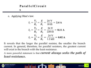
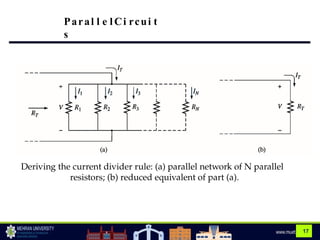
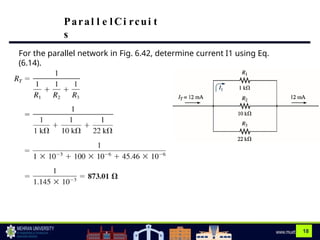
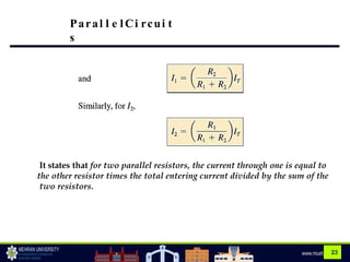
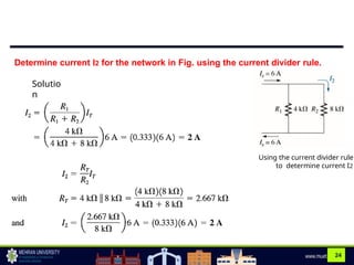
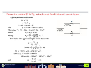
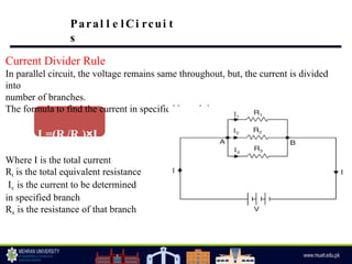
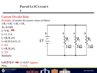
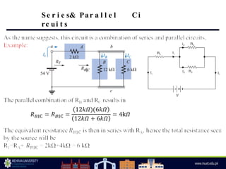
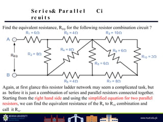
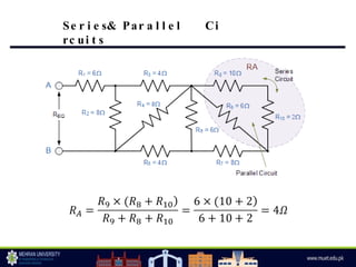
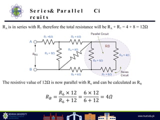
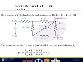
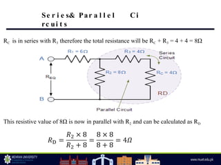
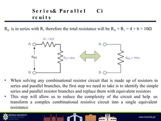
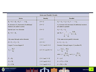
O B JEC
TIVES
 Par a l l e l Ci rc ui t s
 Cur re nt Di v i de r Rul
e
 Se r i e s & Par a l l e l Ci
rc ui t s
Previously we have discussed:
• Ohm’s Law & its corresponding equations
• Series circuit
• Voltage divider rule
Resistances in Parallel
The term parallel is used so often to describe a physical arrangement between two
elements that most individuals are aware of its general characteristics.
In general, two elements, branches, or circuits are in parallel if they have two points
in common.
Par a l l e l Ci rc
ui t s
(a) Parallel resistors; (b) R1 and R2 are in parallel; (c) R3 is in parallel with the series
combination of R1 and R2.
Resistances in Parallel
When one end of each resistance is joined to a common point and the other end of
each resistance is joined to another common point so that there are as many paths for
current flow as the number of resistances, it is called a parallel circuit.
By Ohm’s Law
V=IR I=V/R
Here, V=V1=V2=V3 and I=I1+I2+I3
I1=V/R1, I2=V/R2, I3=V/R3
Since I=I1+I2+I3,
V/R=V/R1+V/R2+V/R3
V/R= V(1/R1+1/R2+1/R3)
1/R=1/R1+1/R2+1/R3
Hence, when a number of resistances are connected in parallel, the reciprocal of total
resistance is equal to the sum of the reciprocals of the individual resistances.
Par a l l e l Ci rc
ui t s
The main characteristics of parallel circuit are:
• Same voltage acts across all parts of the circuit
• The total current in the circuit is equal to the sum of currents in its parallel
branches
• Conductance are additive (1/R=1/R1+1/R2+1/R3 and 1/R=G, therefore G=G1+G2+G3)
• The reciprocal of the total resistance is equal to the sum of the reciprocals of the
individual resistances
• As the number of parallel branches is increased, the total resistance of the circuit
is decreased
• The total resistance of the circuit is always less than the smallest of
the resistances
Par a l l e l Ci rc
ui t s
Advantages of Parallel Circuits
The most useful property of a parallel circuit is the fact that potential difference has
the same value between the terminals of each branch of parallel circuit. This feature
of the parallel circuit offers the following advantages:
(i)The appliances rated for the same voltage but different powers can be connected in
parallel without disturbing each other’s performance. Thus a 230 V, 230 W TV
receiver can be operated independently in parallel with a 230 V, 40 W lamp.
(ii)If a break occurs in any one of the branch circuits, it will have no effect on other
Branch circuit
Par a l l e l Ci rc
ui t s
Two resistances in Parallel
Par a l l e l Ci rc
ui t s
Example: Determine the total resistance for the
network?
Par a l l e l Ci rc
ui t s
Home Work: Find the total resistance of the network shown below:
1.
2.
Par a l l e l Ci rc
ui t s
Par a l l e l Ci rc
ui t s
For the parallel network in Fig. :
a. Find the total resistance.
b. Calculate the source current.
c. Determine the current through each parallel branch.
d. Show that KCL is verified
12
a.
Par a l l e l Ci rc
ui t s
13
For the parallel network in Fig.
a. Find the total resistance.
b. Calculate the source current.
c. Determine the current through each
branch.
Paral l e lCi rcui t
s
14
a.
Paral l e lCi rcui t
s
15
It reveals that the larger the parallel resistor, the smaller the branch
current. In general, therefore, for parallel resistors, the greatest current
will exist in the branch with the least resistance.
A more powerful statement is that current always seeks the path of
least resistance.
Paral l e l Ci rcui t
s
Current Divider Rule
For series circuits we have the powerful voltage divider rule for finding
the voltage across a resistor in a series circuit. We now introduce the
equally powerful current divider rule (CDR) for finding the current
through a resistor in a parallel circuit.
• For two parallel elements of equal value, the current will
divide equally.
• For parallel elements with different values, the smaller the resistance,
the greater the share of input current.
• For parallel elements of different values, the current will split with a
ratio equal to the inverse of their resistor values.
Paral l e lCi rcui t
s
17
Deriving the current divider rule: (a) parallel network of N parallel
resistors; (b) reduced equivalent of part (a).
Paral l e lCi rcui t
s
18
For the parallel network in Fig. 6.42, determine current I1 using Eq.
(6.14).
Paral l e l Ci rcui t
s
19
Note also that for a parallel network, the current through the smallest resistor
will be very close to the total entering current if the other parallel elements of
the configuration are much larger in magnitude.
In this example, the current through R1 is very close to the total current
because R1 is 10 times less than the next smallest resistor.
Paral l e lCi rcui t
s
20
Paral l e lCi rcui t
s
21
Paral l e lCi rcui t
s
22
Special Case: Two Parallel Resistors
For the case of two parallel resistors as shown in Fig 6.43, the total
resistance is determined by
Substituting RT for current I1 results
in
Paral l e lCi rcui t
s
23
It states that for two parallel resistors, the current through one is equal to
the other resistor times the total entering current divided by the sum of the
two resistors.
Paral l e lCi rcui t
s
24
Determine current I2 for the network in Fig. using the current divider rule.
Using the current divider rule
to determine current I2
Solutio
n
25
Determine resistor R1 in Fig. to implement the division of current shown.
Current Divider Rule
In parallel circuit, the voltage remains same throughout, but, the current is divided
into
number of branches.
The formula to find the current in specified branch is:
Ix=(Rt/Rx)×I
Where I is the total current
Rt is the total equivalent resistance
Ix is the current to be determined
in specified branch
Rx is the resistance of that branch
Paral l e lCi rcui t
s
Current Divider Rule
Example: (Consider the resistor values in Ohms)
1/RT=1/R1+1/R2+1/R3
RT=0.54Ω
It=V/RT
It=11.11A
I1=(Rt/R1)×It
I1=(0.54/1)×11.11
I1=6A
I2=(Rt/R2)×It
I2=2A
Similarly
I3=2.97A
Now,
I=I1+I2+I3
I=6+2+2.97 I=10.97 Approx
I=11A
Paral l e lCi rcui t
s
Se r i e s& Par a l l e l Ci
rc ui t s
Applications of Series-parallel circuits
Series-parallel circuits combine the advantages of both series and parallel. A few
common applications of series-parallel circuits are given below:
(i) In an automobile, the starting, lighting and ignition circuits are all individual
circuits
joined to make a series-parallel circuit drawing its power from one battery.
(ii)Radio and television receivers contain a number of separate circuits such as tuning
circuits, RF amplifiers, oscillator, detector and picture tube circuits. Individually, they
may be simple series or parallel circuits. However, when the receiver is considered as a
whole, the result is a series-parallel circuit.
(iii)Power supplies are connected in series to get a higher voltage and in parallel to get
a higher current.
Seri es & Paral l e lCi rcui t
s
Find the equivalent resistance, REQ for the following resistor combination circuit ?
Again, at first glance this resistor ladder network may seem a complicated task, but
as before it is just a combination of series and parallel resistors connected together.
Starting from the right hand side and using the simplified equation for two parallel
resistors, we can find the equivalent resistance of the R8 to R10 combination and
call it RA.
Se r i e s& Par a l l e l Ci
rc ui t s
Se r i e s& Par a l l e l Ci
rc ui t s
RA is in series with R7 therefore the total resistance will be RA + R7 = 4 + 8 = 12Ω
The resistive value of 12Ω is now parallel with R6 and can be calculated as RB
Se r i e s& Par a l l e l Ci
rc ui t s
RB is in series with R5 therefore the total resistance will be RB + R5 = 4 + 4 = 8Ω
This resistive value of 8Ω is now in parallel with R4 and can be calculated as RC
Se r i e s& Par a l l e l Ci
rc ui t s
RC is in series with R3 therefore the total resistance will be RC + R3 = 4 + 4 = 8Ω
This resistive value of 8Ω is now in parallel with R2 and can be calculated as RD
Se r i e s& Par a l l e l Ci
rc ui t s
RD is in series with R1 therefore the total resistance will be RD + R1 = 4 + 6 = 10Ω
• When solving any combinational resistor circuit that is made up of resistors in
series and parallel branches, the first step we need to take is to identify the simple
series and parallel resistor branches and replace them with equivalent resistors
• This step will allow us to reduce the complexity of the circuit and help us
transform a complex combinational resistive circuit into a single equivalent
resistance
Se r i e s& Par a l l e l Ci
rc ui t s
Example 2.26-2.27 (Page-54)
Example 2.28 – 2.29 (Page-56)
Find the equivalent resistance ?
Basic Electrical Engineering by VK Mehta
Note: The book is in the files section of the Team.
Se r i e s& Par a l l e l Ci
rc ui t s
37
38
References &
Acknowledgments
• Introductory Circuit Analysis by
R.Bolyested

03. Parallel circuits , CDR & Series-Parallel Circuits.pptx

  • 1.
    O B JEC TIVES Par a l l e l Ci rc ui t s  Cur re nt Di v i de r Rul e  Se r i e s & Par a l l e l Ci rc ui t s Previously we have discussed: • Ohm’s Law & its corresponding equations • Series circuit • Voltage divider rule
  • 2.
    Resistances in Parallel Theterm parallel is used so often to describe a physical arrangement between two elements that most individuals are aware of its general characteristics. In general, two elements, branches, or circuits are in parallel if they have two points in common. Par a l l e l Ci rc ui t s (a) Parallel resistors; (b) R1 and R2 are in parallel; (c) R3 is in parallel with the series combination of R1 and R2.
  • 3.
    Resistances in Parallel Whenone end of each resistance is joined to a common point and the other end of each resistance is joined to another common point so that there are as many paths for current flow as the number of resistances, it is called a parallel circuit. By Ohm’s Law V=IR I=V/R Here, V=V1=V2=V3 and I=I1+I2+I3 I1=V/R1, I2=V/R2, I3=V/R3 Since I=I1+I2+I3, V/R=V/R1+V/R2+V/R3 V/R= V(1/R1+1/R2+1/R3) 1/R=1/R1+1/R2+1/R3 Hence, when a number of resistances are connected in parallel, the reciprocal of total resistance is equal to the sum of the reciprocals of the individual resistances. Par a l l e l Ci rc ui t s
  • 4.
    The main characteristicsof parallel circuit are: • Same voltage acts across all parts of the circuit • The total current in the circuit is equal to the sum of currents in its parallel branches • Conductance are additive (1/R=1/R1+1/R2+1/R3 and 1/R=G, therefore G=G1+G2+G3) • The reciprocal of the total resistance is equal to the sum of the reciprocals of the individual resistances • As the number of parallel branches is increased, the total resistance of the circuit is decreased • The total resistance of the circuit is always less than the smallest of the resistances Par a l l e l Ci rc ui t s
  • 5.
    Advantages of ParallelCircuits The most useful property of a parallel circuit is the fact that potential difference has the same value between the terminals of each branch of parallel circuit. This feature of the parallel circuit offers the following advantages: (i)The appliances rated for the same voltage but different powers can be connected in parallel without disturbing each other’s performance. Thus a 230 V, 230 W TV receiver can be operated independently in parallel with a 230 V, 40 W lamp. (ii)If a break occurs in any one of the branch circuits, it will have no effect on other Branch circuit Par a l l e l Ci rc ui t s
  • 6.
    Two resistances inParallel Par a l l e l Ci rc ui t s
  • 7.
    Example: Determine thetotal resistance for the network? Par a l l e l Ci rc ui t s
  • 8.
    Home Work: Findthe total resistance of the network shown below: 1. 2. Par a l l e l Ci rc ui t s
  • 9.
    Par a ll e l Ci rc ui t s For the parallel network in Fig. : a. Find the total resistance. b. Calculate the source current. c. Determine the current through each parallel branch. d. Show that KCL is verified
  • 10.
    12 a. Par a ll e l Ci rc ui t s
  • 11.
    13 For the parallelnetwork in Fig. a. Find the total resistance. b. Calculate the source current. c. Determine the current through each branch. Paral l e lCi rcui t s
  • 12.
    14 a. Paral l elCi rcui t s
  • 13.
    15 It reveals thatthe larger the parallel resistor, the smaller the branch current. In general, therefore, for parallel resistors, the greatest current will exist in the branch with the least resistance. A more powerful statement is that current always seeks the path of least resistance. Paral l e l Ci rcui t s
  • 14.
    Current Divider Rule Forseries circuits we have the powerful voltage divider rule for finding the voltage across a resistor in a series circuit. We now introduce the equally powerful current divider rule (CDR) for finding the current through a resistor in a parallel circuit. • For two parallel elements of equal value, the current will divide equally. • For parallel elements with different values, the smaller the resistance, the greater the share of input current. • For parallel elements of different values, the current will split with a ratio equal to the inverse of their resistor values. Paral l e lCi rcui t s
  • 15.
    17 Deriving the currentdivider rule: (a) parallel network of N parallel resistors; (b) reduced equivalent of part (a). Paral l e lCi rcui t s
  • 16.
    18 For the parallelnetwork in Fig. 6.42, determine current I1 using Eq. (6.14). Paral l e l Ci rcui t s
  • 17.
    19 Note also thatfor a parallel network, the current through the smallest resistor will be very close to the total entering current if the other parallel elements of the configuration are much larger in magnitude. In this example, the current through R1 is very close to the total current because R1 is 10 times less than the next smallest resistor. Paral l e lCi rcui t s
  • 18.
    20 Paral l elCi rcui t s
  • 19.
    21 Paral l elCi rcui t s
  • 20.
    22 Special Case: TwoParallel Resistors For the case of two parallel resistors as shown in Fig 6.43, the total resistance is determined by Substituting RT for current I1 results in Paral l e lCi rcui t s
  • 21.
    23 It states thatfor two parallel resistors, the current through one is equal to the other resistor times the total entering current divided by the sum of the two resistors. Paral l e lCi rcui t s
  • 22.
    24 Determine current I2for the network in Fig. using the current divider rule. Using the current divider rule to determine current I2 Solutio n
  • 23.
    25 Determine resistor R1in Fig. to implement the division of current shown.
  • 24.
    Current Divider Rule Inparallel circuit, the voltage remains same throughout, but, the current is divided into number of branches. The formula to find the current in specified branch is: Ix=(Rt/Rx)×I Where I is the total current Rt is the total equivalent resistance Ix is the current to be determined in specified branch Rx is the resistance of that branch Paral l e lCi rcui t s
  • 25.
    Current Divider Rule Example:(Consider the resistor values in Ohms) 1/RT=1/R1+1/R2+1/R3 RT=0.54Ω It=V/RT It=11.11A I1=(Rt/R1)×It I1=(0.54/1)×11.11 I1=6A I2=(Rt/R2)×It I2=2A Similarly I3=2.97A Now, I=I1+I2+I3 I=6+2+2.97 I=10.97 Approx I=11A Paral l e lCi rcui t s
  • 26.
    Se r ie s& Par a l l e l Ci rc ui t s
  • 27.
    Applications of Series-parallelcircuits Series-parallel circuits combine the advantages of both series and parallel. A few common applications of series-parallel circuits are given below: (i) In an automobile, the starting, lighting and ignition circuits are all individual circuits joined to make a series-parallel circuit drawing its power from one battery. (ii)Radio and television receivers contain a number of separate circuits such as tuning circuits, RF amplifiers, oscillator, detector and picture tube circuits. Individually, they may be simple series or parallel circuits. However, when the receiver is considered as a whole, the result is a series-parallel circuit. (iii)Power supplies are connected in series to get a higher voltage and in parallel to get a higher current. Seri es & Paral l e lCi rcui t s
  • 28.
    Find the equivalentresistance, REQ for the following resistor combination circuit ? Again, at first glance this resistor ladder network may seem a complicated task, but as before it is just a combination of series and parallel resistors connected together. Starting from the right hand side and using the simplified equation for two parallel resistors, we can find the equivalent resistance of the R8 to R10 combination and call it RA. Se r i e s& Par a l l e l Ci rc ui t s
  • 29.
    Se r ie s& Par a l l e l Ci rc ui t s
  • 30.
    RA is inseries with R7 therefore the total resistance will be RA + R7 = 4 + 8 = 12Ω The resistive value of 12Ω is now parallel with R6 and can be calculated as RB Se r i e s& Par a l l e l Ci rc ui t s
  • 31.
    RB is inseries with R5 therefore the total resistance will be RB + R5 = 4 + 4 = 8Ω This resistive value of 8Ω is now in parallel with R4 and can be calculated as RC Se r i e s& Par a l l e l Ci rc ui t s
  • 32.
    RC is inseries with R3 therefore the total resistance will be RC + R3 = 4 + 4 = 8Ω This resistive value of 8Ω is now in parallel with R2 and can be calculated as RD Se r i e s& Par a l l e l Ci rc ui t s
  • 33.
    RD is inseries with R1 therefore the total resistance will be RD + R1 = 4 + 6 = 10Ω • When solving any combinational resistor circuit that is made up of resistors in series and parallel branches, the first step we need to take is to identify the simple series and parallel resistor branches and replace them with equivalent resistors • This step will allow us to reduce the complexity of the circuit and help us transform a complex combinational resistive circuit into a single equivalent resistance Se r i e s& Par a l l e l Ci rc ui t s
  • 34.
    Example 2.26-2.27 (Page-54) Example2.28 – 2.29 (Page-56) Find the equivalent resistance ? Basic Electrical Engineering by VK Mehta Note: The book is in the files section of the Team. Se r i e s& Par a l l e l Ci rc ui t s
  • 35.
  • 36.
    38 References & Acknowledgments • IntroductoryCircuit Analysis by R.Bolyested