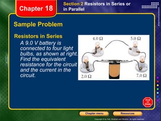
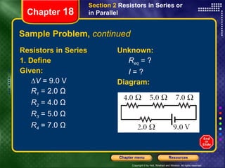
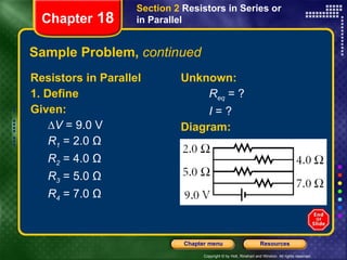
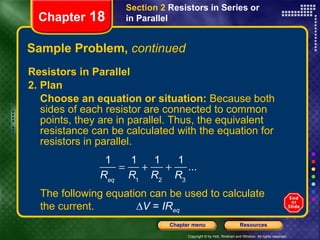
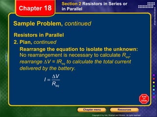
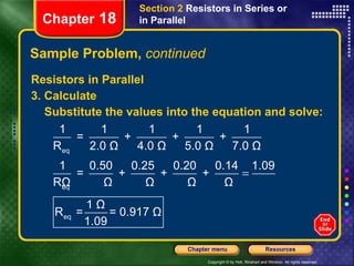
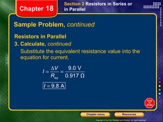
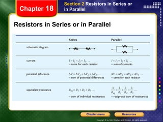
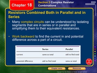
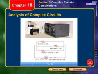
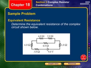
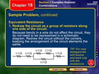
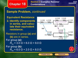
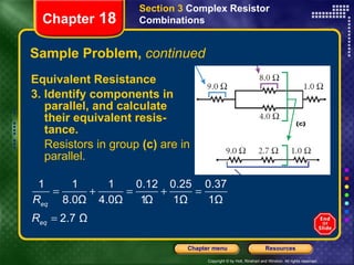
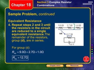
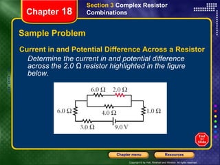
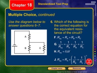
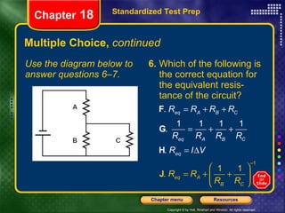
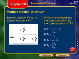
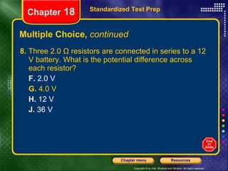
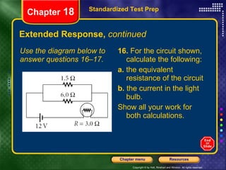
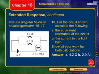
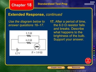
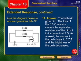
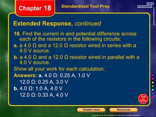
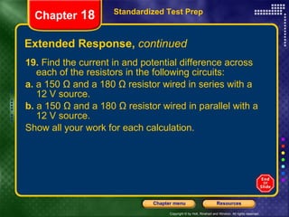
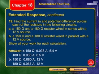
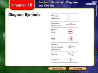
How to Use This Presentation To View the presentation as a slideshow with effects  select  “View”  on the menu bar and click on  “Slide Show.” To advance through the presentation, click the right-arrow key or the space bar. From the resources slide, click on any resource to see a presentation for that resource. From the Chapter menu screen click on any lesson to go directly to that lesson’s presentation. You may exit the slide show at any time by pressing  the  Esc  key.
Chapter Presentation Transparencies Sample Problems Visual Concepts Standardized Test Prep Resources
Table of Contents Section 1  Schematic Diagrams and Circuits Section 2  Resistors in Series or in Parallel Section 3  Complex Resistor Combination Circuits and Circuit Elements Chapter  18
Objectives Interpret   and   construct   circuit diagrams. Identify   circuits as open or closed. Deduce   the potential difference across the circuit load, given the potential difference across the battery’s terminals. Section 1  Schematic Diagrams and Circuits Chapter  18
Schematic Diagrams A  schematic diagram  is a representation of a circuit that uses lines to represent wires and different symbols to represent components. Some  symbols used in schematic diagrams  are shown at right. Section 1  Schematic Diagrams and Circuits Chapter  18
Schematic Diagram and Common Symbols Chapter  18 Section 1  Schematic Diagrams and Circuits
Electric Circuits An  electric circuit  is   a set of electrical components connected such that they provide one or more complete paths for the movement of charges. A schematic diagram for a circuit is sometimes called a   circuit diagram. Any element or group of elements in a circuit that dissipates energy is called a   load. Section 1  Schematic Diagrams and Circuits Chapter  18
Electric Circuits,  continued A circuit which contains a complete path for electrons to follow is called a   closed circuit. Without a complete path, there is no charge flow and therefore no current. This situation is called an   open circuit. A   short circuit   is a closed circuit that does not contain a load.  Short circuits can be hazardous. Section 1  Schematic Diagrams and Circuits Chapter  18
Electric Circuits,  continued The source of potential difference and electrical energy is the circuits   emf. Any device that  transforms nonelectrical energy into electrical energy , such as a battery or a generator, is a source of  emf. If the internal resistance of a battery is neglected,  the emf equals the potential difference  across the source’s two terminals. Section 1  Schematic Diagrams and Circuits Chapter  18
Chapter  18 Section 1  Schematic Diagrams and Circuits Internal Resistance, emf, and Terminal Voltage
Electric Circuits,  continued The   terminal voltage   is the potential difference across a battery’s positive and negative terminals. For conventional current, the terminal voltage is  less than the emf. The  potential difference across a load  equals the terminal voltage. Section 1  Schematic Diagrams and Circuits Chapter  18
Light Bulb Chapter  18 Section 1  Schematic Diagrams and Circuits
Objectives Calculate   the equivalent resistance for a circuit of resistors in series, and find the current in and potential difference across each resistor in the circuit. Calculate   the equivalent resistance for a circuit of resistors in parallel, and find the current in and potential difference across each resistor in the circuit. Section 2  Resistors in Series or in Parallel Chapter  18
Resistors in Series A   series   circuit describes two or more components of a circuit that provide a single path for current.   Resistors in series  carry the same current. The   equivalent resistance   can be used to find the current in a circuit. The  equivalent resistance in a series circuit  is the   sum of the circuit’s resistances. R eq  =  R 1  +  R 2  +  R 3 … Section 2  Resistors in Series or in Parallel Chapter  18
Resistors in Series Chapter  18 Section 2  Resistors in Series or in Parallel
Resistors in Series,  continued Two or more resistors in the actual circuit have the same effect on the current as  one equivalent resistor. The  total current  in a series circuit equals the potential difference divided by the equivalent resistance. Section 2  Resistors in Series or in Parallel Chapter  18
Sample Problem Resistors in Series A 9.0 V battery is connected to four light bulbs, as shown at right. Find the equivalent resistance for the circuit and the current in the circuit. Chapter  18 Section 2  Resistors in Series or in Parallel
Sample Problem,  continued Resistors in Series 1. Define Given: ∆ V  = 9.0 V R 1  = 2.0 Ω R 2  = 4.0 Ω R 3  = 5.0 Ω R 4  = 7.0 Ω Unknown: R eq  = ? I  = ? Diagram: Chapter  18 Section 2  Resistors in Series or in Parallel
Sample Problem,  continued Resistors in Series 2. Plan Choose an equation or situation:  Because the resistors are connected end to end, they are in series. Thus, the equivalent resistance can be calculated with the equation for resistors in series. R eq  = R 1  +  R 2  + R 3 … The following equation can be used to calculate the current. ∆ V  =  IR eq Chapter  18 Section 2  Resistors in Series or in Parallel
Sample Problem,  continued Resistors in Series 2. Plan,  continued Rearrange the equation to isolate the unknown:  No rearrangement is necessary to calculate  R eq , but ∆V = IR eq  must be rearranged to calculate the current. Chapter  18 Section 2  Resistors in Series or in Parallel
Sample Problem,  continued Resistors in Series 3. Calculate Substitute the values into the equation and solve: Chapter  18 Substitute the equivalent resistance value into the equation for current. Section 2  Resistors in Series or in Parallel
Sample Problem,  continued Resistors in Series 4. Evaluate For resistors connected in series, the equivalent resistance should be greater than the largest resistance in the circuit. 18.0 Ω > 7.0 Ω Chapter  18 Section 2  Resistors in Series or in Parallel
Resistors in Series,  continued Series circuits  require all elements to conduct electricity As seen below,  a burned out filament  in a string of bulbs has the same effect as an open switch. Because the circuit is no longer complete, there is no current. Section 2  Resistors in Series or in Parallel Chapter  18
Comparing Resistors in Series and in Parallel Chapter  18 Section 2  Resistors in Series or in Parallel
Resistors in Parallel A  parallel  arrangement describes two or more com-ponents of a circuit that provide separate conducting paths for current because the components are connected across common points or junctions Lights wired in parallel  have more than one path for current.  Parallel circuits do not require all elements to conduct. Section 2  Resistors in Series or in Parallel Chapter  18
Resistors in Parallel Chapter  18 Section 2  Resistors in Series or in Parallel
Resistors in Parallel,  continued Resistors in parallel have the  same potential differences  across them. The sum of currents in parallel resistors equals the  total current. The  equivalent resistance  of resistors in parallel can be calculated using a reciprocal relationship Section 2  Resistors in Series or in Parallel Chapter  18
Sample Problem Resistors in Parallel A 9.0 V battery is connected to four resistors, as shown at right. Find the equivalent resistance for the circuit and the total current in the circuit. Chapter  18 Section 2  Resistors in Series or in Parallel
Sample Problem,  continued Resistors in Parallel 1. Define Given: ∆ V  = 9.0 V R 1  = 2.0 Ω R 2  = 4.0 Ω R 3  = 5.0 Ω R 4  = 7.0 Ω Unknown: R eq  = ? I  = ? Diagram: Chapter  18 Section 2  Resistors in Series or in Parallel
Sample Problem,  continued Resistors in Parallel 2. Plan Choose an equation or situation:  Because both sides of each resistor are connected to common points, they are in parallel. Thus, the equivalent resistance can be calculated with the equation for resistors in parallel. Chapter  18 Section 2  Resistors in Series or in Parallel The following equation can be used to calculate the current. ∆ V  =  IR eq
Sample Problem,  continued Resistors in Parallel 2. Plan,  continued Rearrange the equation to isolate the unknown:  No rearrangement is necessary to calculate  R eq ; rearrange ∆V = IR eq  to calculate the total current delivered by the battery. Chapter  18 Section 2  Resistors in Series or in Parallel
Sample Problem,  continued Resistors in Parallel 3. Calculate Substitute the values into the equation and solve: Chapter  18 Section 2  Resistors in Series or in Parallel
Sample Problem,  continued Resistors in Parallel 3. Calculate,  continued Substitute the equivalent resistance value into the equation for current. Chapter  18 Section 2  Resistors in Series or in Parallel
Sample Problem,  continued Resistors in Parallel 4. Evaluate For resistors connected in parallel, the equivalent resistance should be less than the smallest resistance in the circuit. 0.917 Ω < 2.0 Ω Chapter  18 Section 2  Resistors in Series or in Parallel
Resistors in Series or in Parallel Chapter  18 Section 2  Resistors in Series or in Parallel
Objectives Calculate   the equivalent resistance for a complex circuit involving both series and parallel portions. Calculate   the current in and potential difference across individual elements within a complex circuit. Section 3  Complex Resistor Combinations Chapter  18
Resistors Combined Both in Parallel and in Series Many  complex circuits  can be understood by isolating segments that are in series or in parallel and simplifying them to their equivalent resistances. Work backward  to find the current in and potential difference across a part of a circuit. Section 3  Complex Resistor Combinations Chapter  18
Analysis of Complex Circuits Chapter  18 Section 3  Complex Resistor Combinations
Sample Problem Equivalent Resistance Determine the equivalent resistance of the complex circuit shown below. Section 3  Complex Resistor Combinations Chapter  18
Sample Problem,  continued Equivalent Resistance Reasoning The best approach is to divide the circuit into groups of series and parallel resistors. This way, the methods presented in Sample Problems A and B can be used to calculate the equivalent resistance for each group. Section 3  Complex Resistor Combinations Chapter  18
Sample Problem,  continued Equivalent Resistance 1. Redraw the circuit as a group of resistors along one side of the circuit. Because bends in a wire do not affect the circuit, they do not need to be represented in a schematic diagram. Redraw the circuit without the corners, keeping the arrangement of the circuit elements the same. Section 3  Complex Resistor Combinations Chapter  18 TIP: For now, disregard the emf source, and work only with the resistances.
Sample Problem,  continued Equivalent Resistance 2. Identify components in series, and calcu-late their equivalent resistance. Section 3  Complex Resistor Combinations Chapter  18 Resistors in group  (a)  and (b)  are in series. For group  (a):   R eq  = 3.0 Ω + 6.0 Ω = 9.0 Ω For group  (b):   R eq   = 6.0 Ω + 2.0 Ω = 8.0 Ω
Sample Problem,  continued Equivalent Resistance 3. Identify components in parallel, and calculate their equivalent resis-tance. Resistors in group  (c)  are in parallel. Section 3  Complex Resistor Combinations Chapter  18
Sample Problem,  continued Equivalent Resistance 4. Repeat steps 2 and 3 until the resistors in the circuit are reduced to a single equivalent resistance. The remainder of the resistors, group  (d),  are in series. Section 3  Complex Resistor Combinations Chapter  18
Sample Problem Current in and Potential Difference Across a Resistor Determine the current in and potential difference across the 2.0 Ω resistor highlighted in the figure below. Section 3  Complex Resistor Combinations Chapter  18
Sample Problem,  continued Current in and Potential Difference Across a Resistor Reasoning First determine the total circuit current by reducing the resistors to a single equivalent resistance. Then rebuild the circuit in steps, calculating the current and potential difference for the equivalent resistance of each group until the current in and potential difference across the 2.0 Ω resistor are known. Section 3  Complex Resistor Combinations Chapter  18
Sample Problem,  continued Current in and Potential Difference Across a Resistor 1. Determine the equivalent resistance of the circuit. The equivalent resistance of the circuit is 12.7 Ω, as calculated in the previous Sample Problem. Section 3  Complex Resistor Combinations Chapter  18
Sample Problem,  continued Current in and Potential Difference Across a Resistor 2. Calculate the total current in the circuit. Substitute the potential difference and equivalent resistance in ∆ V  =  IR,  and rearrange the equation to find the current delivered by the battery. Section 3  Complex Resistor Combinations Chapter  18
Sample Problem,  continued 3. Determine a path from the equivalent resistance found in step 1 to the 2.0 Ω resistor. Section 3  Complex Resistor Combinations Chapter  18 Review the path taken to find the equivalent resistance in the figure at right, and work backward through this path. The equivalent resistance for the entire circuit is the same as the equivalent resistance for group  (d).  The center resistor in group  (d)  in turn is the equivalent resistance for group  (c).  The top resistor in group  (c)  is the equivalent resistance for group  (b),  and the right resistor in group  (b)  is the 2.0 Ω resistor.
Sample Problem,  continued Current in and Potential Difference Across a Resistor 4. Follow the path determined in step 3, and calculate the current in and potential difference across each equivalent resistance. Repeat this process until the desired values are found. Section 3  Complex Resistor Combinations Chapter  18
Sample Problem,  continued 4. A. Regroup, evaluate, and calculate.  Replace the circuit’s equivalent resistance with group  (d).  The resistors in group  (d)  are in series; therefore, the current in each resistor is the same as the current in the equivalent resistance, which equals 0.71 A. The potential difference across the 2.7 Ω resistor in group  (d)  can be calculated using ∆ V  =  IR . Section 3  Complex Resistor Combinations Chapter  18 Given:   I  = 0.71 A  R  = 2.7 Ω Unknown:  ∆V  = ? ∆ V  =  IR  = (0.71 A)(2.7 Ω) = 1.9 V
Sample Problem,  continued 4. B. Regroup, evaluate, and calculate.  Replace the center resistor with group  (c).   The resistors in group  (c)  are in parallel; therefore, the potential difference across each resistor is the same as the potential difference across the 2.7 Ω equivalent resistance, which equals 1.9 V. The current in the 8.0 Ω resistor in group  (c)  can be calculated using ∆V = IR. Section 3  Complex Resistor Combinations Chapter  18 Given:   ∆V =  1.9 V   R  = 8.0 Ω Unknown:  I  = ?
Sample Problem,  continued 4. C. Regroup, evaluate, and calculate. Replace the 8.0 Ω resistor with group  (b). The resistors in group  (b)  are in series; therefore, the current in each resistor is the same as the current in the 8.0 Ω equivalent resistance, which equals 0.24 A.   Section 3  Complex Resistor Combinations Chapter  18 The potential difference across the 2.0 Ω resistor can be calculated using ∆ V  =  IR. Given:   I  = 0.24 A  R  = 2.0 Ω Unknown:  ∆V  = ?
Multiple Choice 1.  Which of the following is the correct term for a circuit that does not have a closed-loop path for electron flow? A.  closed circuit B.  dead circuit C.  open circuit D.  short circuit Standardized Test Prep Chapter  18
Multiple Choice,  continued 1.  Which of the following is the correct term for a circuit that does not have a closed-loop path for electron flow? A.  closed circuit B.  dead circuit C.  open circuit D.  short circuit Standardized Test Prep Chapter  18
Multiple Choice,  continued 2.  Which of the following is the correct term for a circuit in which the load has been unintentionally bypassed? F.  closed circuit G.  dead circuit H.  open circuit J.  short circuit Standardized Test Prep Chapter  18
Multiple Choice,  continued Use the diagram below to answer questions 3–5. 3.  Which of the circuit elements contribute to the load of the circuit? A.  Only A B.  A and B, but not C C.  Only C D.  A, B, and C Standardized Test Prep Chapter  18
Multiple Choice,  continued Use the diagram below to answer questions 3–5. 4.  Which of the following is the correct equation for the equivalent resis-tance of the circuit? Standardized Test Prep Chapter  18
Multiple Choice,  continued Use the diagram below to answer questions 3–5. 5.  Which of the following is the correct equation for the current in the resistor? Standardized Test Prep Chapter  18
Multiple Choice,  continued Use the diagram below to answer questions 6–7. 6.  Which of the following is the correct equation for the equivalent resis-tance of the circuit? Standardized Test Prep Chapter  18
Multiple Choice,  continued Use the diagram below to answer questions 6–7. 7.  Which of the following is the correct equation for the current in resistor B? Standardized Test Prep Chapter  18
Multiple Choice,  continued 8.  Three 2.0 Ω resistors are connected in series to a 12 V battery. What is the potential difference across each resistor? F.  2.0 V G.  4.0 V H.  12 V J.  36 V Standardized Test Prep Chapter  18
Multiple Choice,  continued Use the following passage to answer questions 9–11. Six light bulbs are connected in parallel to a 9.0 V battery. Each bulb has a resistance of 3.0 Ω. 9.  What is the potential difference across each bulb? A.  1.5 V B.  3.0 V C.  9.0 V D.  27 V Standardized Test Prep Chapter  18
Multiple Choice,  continued Use the following passage to answer questions 9–11. Six light bulbs are connected in parallel to a 9.0 V battery. Each bulb has a resistance of 3.0 Ω. 10.  What is the current in each bulb? F.  0.5 A G.  3.0 A H.  4.5 A J.  18 A Standardized Test Prep Chapter  18
Multiple Choice,  continued Use the following passage to answer questions 9–11. Six light bulbs are connected in parallel to a 9.0 V battery. Each bulb has a resistance of 3.0 Ω. 11.  What is the total current in the circuit? A.  0.5 A B.  3.0 A C.  4.5 A D.  18 A Standardized Test Prep Chapter  18
Short Response 12.  Which is greater, a battery’s terminal voltage or the same battery’s emf? Explain why these two quantities are not equal. Standardized Test Prep Chapter  18
Short Response,  continued 12.  Which is greater, a battery’s terminal voltage or the same battery’s emf? Explain why these two quantities are not equal. Answer:   A battery’s emf is slightly greater than its terminal voltage. The difference is due to the battery’s internal resistance. Standardized Test Prep Chapter  18
Short Response,  continued 13.  Describe how a short circuit could lead to a fire. Standardized Test Prep Chapter  18
Short Response,  continued 13.  Describe how a short circuit could lead to a fire. Answer:   In a short circuit, the equivalent resistance of the circuit drops very low, causing the current to be very high. The higher current can cause wires still in the circuit to overheat, which may in turn cause a fire in materials contacting the wires. Standardized Test Prep Chapter  18
Short Response,  continued 14.  Explain the advantage of wiring the bulbs in a string of decorative lights in parallel rather than in series. Standardized Test Prep Chapter  18
Short Response,  continued 14.  Explain the advantage of wiring the bulbs in a string of decorative lights in parallel rather than in series. Answer:  If one bulb is removed, the other bulbs will still carry current. Standardized Test Prep Chapter  18
Extended Response 15.  Using standard symbols for circuit elements, draw a diagram of a circuit that contains a battery, an open switch, and a light bulb in parallel with a resistor. Add an arrow to indicate the direction of current if the switch were closed. Standardized Test Prep Chapter  18
Extended Response,  continued 15.  Using standard symbols for circuit elements, draw a diagram of a circuit that contains a battery, an open switch, and a light bulb in parallel with a resistor. Add an arrow to indicate the direction of current if the switch were closed. Answer: Standardized Test Prep Chapter  18
Extended Response,  continued Use the diagram below to answer questions 16–17. 16.  For the circuit shown, calculate the following: a.  the equivalent resistance of the circuit b.  the current in the light bulb. Show all your work for both calculations. Standardized Test Prep Chapter  18
Extended Response,  continued Use the diagram below to answer questions 16–17. 16.  For the circuit shown, calculate the following: a.  the equivalent resistance of the circuit b.  the current in the light bulb. Show all your work for both calculations. Answer:   a.  4.2 Ω  b.  2.9 A Standardized Test Prep Chapter  18
Extended Response,  continued Use the diagram below to answer questions 16–17. 17.  After a period of time, the 6.0 Ω resistor fails and breaks. Describe what happens to the brightness of the bulb. Support your answer. Standardized Test Prep Chapter  18
Extended Response,  continued Use the diagram below to answer questions 16–17. 17.   Answer:  The bulb will grow dim. The loss of the 6.0 Ω resistor causes the equivalent resistance of the circuit to increase to 4.5 Ω. As a result, the current in the bulb drops to 2.7 A, and the brightness of the bulb decreases. Standardized Test Prep Chapter  18
Extended Response,  continued Standardized Test Prep Chapter  18 18.  Find the current in and potential difference across each of the resistors in the following circuits: a.  a 4.0 Ω and a 12.0 Ω resistor wired in series with a 4.0 V source. b.  a 4.0 Ω and a 12.0 Ω resistor wired in parallel with a 4.0 V source. Show all your work for each calculation.
Extended Response,  continued 18.  Find the current in and potential difference across each of the resistors in the following circuits: a.  a 4.0 Ω and a 12.0 Ω resistor wired in series with a 4.0 V source. b.  a 4.0 Ω and a 12.0 Ω resistor wired in parallel with a 4.0 V source. Show all your work for each calculation. Answers:   a.  4.0 Ω: 0.25 A, 1.0 V  12.0 Ω: 0.25 A, 3.0 V b.  4.0 Ω: 1.0 A, 4.0 V 12.0 Ω: 0.33 A, 4.0 V Standardized Test Prep Chapter  18
Extended Response,  continued 19.  Find the current in and potential difference across each of the resistors in the following circuits: a.  a 150 Ω and a 180 Ω resistor wired in series with a 12 V source. b.  a 150 Ω and a 180 Ω resistor wired in parallel with a 12 V source. Show all your work for each calculation. Standardized Test Prep Chapter  18
Extended Response,  continued 19.  Find the current in and potential difference across each of the resistors in the following circuits: a.  a 150 Ω and a 180 Ω resistor wired in series with a 12 V source. b.  a 150 Ω and a 180 Ω resistor wired in parallel with a 12 V source. Show all your work for each calculation. Standardized Test Prep Chapter  18 Answer:  a. 150 Ω: 0.036 A, 5.4 V 180 Ω: 0.036 A, 6.5 V b.  150 Ω: 0.080 A, 12 V 180 Ω: 0.067 A, 12 V
Diagram Symbols Section 1  Schematic Diagrams and Circuits Chapter  18

Hp 18 win

  • 1.
    How to UseThis Presentation To View the presentation as a slideshow with effects select “View” on the menu bar and click on “Slide Show.” To advance through the presentation, click the right-arrow key or the space bar. From the resources slide, click on any resource to see a presentation for that resource. From the Chapter menu screen click on any lesson to go directly to that lesson’s presentation. You may exit the slide show at any time by pressing the Esc key.
  • 2.
    Chapter Presentation TransparenciesSample Problems Visual Concepts Standardized Test Prep Resources
  • 3.
    Table of ContentsSection 1 Schematic Diagrams and Circuits Section 2 Resistors in Series or in Parallel Section 3 Complex Resistor Combination Circuits and Circuit Elements Chapter 18
  • 4.
    Objectives Interpret and construct circuit diagrams. Identify circuits as open or closed. Deduce the potential difference across the circuit load, given the potential difference across the battery’s terminals. Section 1 Schematic Diagrams and Circuits Chapter 18
  • 5.
    Schematic Diagrams A schematic diagram is a representation of a circuit that uses lines to represent wires and different symbols to represent components. Some symbols used in schematic diagrams are shown at right. Section 1 Schematic Diagrams and Circuits Chapter 18
  • 6.
    Schematic Diagram andCommon Symbols Chapter 18 Section 1 Schematic Diagrams and Circuits
  • 7.
    Electric Circuits An electric circuit is a set of electrical components connected such that they provide one or more complete paths for the movement of charges. A schematic diagram for a circuit is sometimes called a circuit diagram. Any element or group of elements in a circuit that dissipates energy is called a load. Section 1 Schematic Diagrams and Circuits Chapter 18
  • 8.
    Electric Circuits, continued A circuit which contains a complete path for electrons to follow is called a closed circuit. Without a complete path, there is no charge flow and therefore no current. This situation is called an open circuit. A short circuit is a closed circuit that does not contain a load. Short circuits can be hazardous. Section 1 Schematic Diagrams and Circuits Chapter 18
  • 9.
    Electric Circuits, continued The source of potential difference and electrical energy is the circuits emf. Any device that transforms nonelectrical energy into electrical energy , such as a battery or a generator, is a source of emf. If the internal resistance of a battery is neglected, the emf equals the potential difference across the source’s two terminals. Section 1 Schematic Diagrams and Circuits Chapter 18
  • 10.
    Chapter 18Section 1 Schematic Diagrams and Circuits Internal Resistance, emf, and Terminal Voltage
  • 11.
    Electric Circuits, continued The terminal voltage is the potential difference across a battery’s positive and negative terminals. For conventional current, the terminal voltage is less than the emf. The potential difference across a load equals the terminal voltage. Section 1 Schematic Diagrams and Circuits Chapter 18
  • 12.
    Light Bulb Chapter 18 Section 1 Schematic Diagrams and Circuits
  • 13.
    Objectives Calculate the equivalent resistance for a circuit of resistors in series, and find the current in and potential difference across each resistor in the circuit. Calculate the equivalent resistance for a circuit of resistors in parallel, and find the current in and potential difference across each resistor in the circuit. Section 2 Resistors in Series or in Parallel Chapter 18
  • 14.
    Resistors in SeriesA series circuit describes two or more components of a circuit that provide a single path for current. Resistors in series carry the same current. The equivalent resistance can be used to find the current in a circuit. The equivalent resistance in a series circuit is the sum of the circuit’s resistances. R eq = R 1 + R 2 + R 3 … Section 2 Resistors in Series or in Parallel Chapter 18
  • 15.
    Resistors in SeriesChapter 18 Section 2 Resistors in Series or in Parallel
  • 16.
    Resistors in Series, continued Two or more resistors in the actual circuit have the same effect on the current as one equivalent resistor. The total current in a series circuit equals the potential difference divided by the equivalent resistance. Section 2 Resistors in Series or in Parallel Chapter 18
  • 17.
    Sample Problem Resistorsin Series A 9.0 V battery is connected to four light bulbs, as shown at right. Find the equivalent resistance for the circuit and the current in the circuit. Chapter 18 Section 2 Resistors in Series or in Parallel
  • 18.
    Sample Problem, continued Resistors in Series 1. Define Given: ∆ V = 9.0 V R 1 = 2.0 Ω R 2 = 4.0 Ω R 3 = 5.0 Ω R 4 = 7.0 Ω Unknown: R eq = ? I = ? Diagram: Chapter 18 Section 2 Resistors in Series or in Parallel
  • 19.
    Sample Problem, continued Resistors in Series 2. Plan Choose an equation or situation: Because the resistors are connected end to end, they are in series. Thus, the equivalent resistance can be calculated with the equation for resistors in series. R eq = R 1 + R 2 + R 3 … The following equation can be used to calculate the current. ∆ V = IR eq Chapter 18 Section 2 Resistors in Series or in Parallel
  • 20.
    Sample Problem, continued Resistors in Series 2. Plan, continued Rearrange the equation to isolate the unknown: No rearrangement is necessary to calculate R eq , but ∆V = IR eq must be rearranged to calculate the current. Chapter 18 Section 2 Resistors in Series or in Parallel
  • 21.
    Sample Problem, continued Resistors in Series 3. Calculate Substitute the values into the equation and solve: Chapter 18 Substitute the equivalent resistance value into the equation for current. Section 2 Resistors in Series or in Parallel
  • 22.
    Sample Problem, continued Resistors in Series 4. Evaluate For resistors connected in series, the equivalent resistance should be greater than the largest resistance in the circuit. 18.0 Ω > 7.0 Ω Chapter 18 Section 2 Resistors in Series or in Parallel
  • 23.
    Resistors in Series, continued Series circuits require all elements to conduct electricity As seen below, a burned out filament in a string of bulbs has the same effect as an open switch. Because the circuit is no longer complete, there is no current. Section 2 Resistors in Series or in Parallel Chapter 18
  • 24.
    Comparing Resistors inSeries and in Parallel Chapter 18 Section 2 Resistors in Series or in Parallel
  • 25.
    Resistors in ParallelA parallel arrangement describes two or more com-ponents of a circuit that provide separate conducting paths for current because the components are connected across common points or junctions Lights wired in parallel have more than one path for current. Parallel circuits do not require all elements to conduct. Section 2 Resistors in Series or in Parallel Chapter 18
  • 26.
    Resistors in ParallelChapter 18 Section 2 Resistors in Series or in Parallel
  • 27.
    Resistors in Parallel, continued Resistors in parallel have the same potential differences across them. The sum of currents in parallel resistors equals the total current. The equivalent resistance of resistors in parallel can be calculated using a reciprocal relationship Section 2 Resistors in Series or in Parallel Chapter 18
  • 28.
    Sample Problem Resistorsin Parallel A 9.0 V battery is connected to four resistors, as shown at right. Find the equivalent resistance for the circuit and the total current in the circuit. Chapter 18 Section 2 Resistors in Series or in Parallel
  • 29.
    Sample Problem, continued Resistors in Parallel 1. Define Given: ∆ V = 9.0 V R 1 = 2.0 Ω R 2 = 4.0 Ω R 3 = 5.0 Ω R 4 = 7.0 Ω Unknown: R eq = ? I = ? Diagram: Chapter 18 Section 2 Resistors in Series or in Parallel
  • 30.
    Sample Problem, continued Resistors in Parallel 2. Plan Choose an equation or situation: Because both sides of each resistor are connected to common points, they are in parallel. Thus, the equivalent resistance can be calculated with the equation for resistors in parallel. Chapter 18 Section 2 Resistors in Series or in Parallel The following equation can be used to calculate the current. ∆ V = IR eq
  • 31.
    Sample Problem, continued Resistors in Parallel 2. Plan, continued Rearrange the equation to isolate the unknown: No rearrangement is necessary to calculate R eq ; rearrange ∆V = IR eq to calculate the total current delivered by the battery. Chapter 18 Section 2 Resistors in Series or in Parallel
  • 32.
    Sample Problem, continued Resistors in Parallel 3. Calculate Substitute the values into the equation and solve: Chapter 18 Section 2 Resistors in Series or in Parallel
  • 33.
    Sample Problem, continued Resistors in Parallel 3. Calculate, continued Substitute the equivalent resistance value into the equation for current. Chapter 18 Section 2 Resistors in Series or in Parallel
  • 34.
    Sample Problem, continued Resistors in Parallel 4. Evaluate For resistors connected in parallel, the equivalent resistance should be less than the smallest resistance in the circuit. 0.917 Ω < 2.0 Ω Chapter 18 Section 2 Resistors in Series or in Parallel
  • 35.
    Resistors in Seriesor in Parallel Chapter 18 Section 2 Resistors in Series or in Parallel
  • 36.
    Objectives Calculate the equivalent resistance for a complex circuit involving both series and parallel portions. Calculate the current in and potential difference across individual elements within a complex circuit. Section 3 Complex Resistor Combinations Chapter 18
  • 37.
    Resistors Combined Bothin Parallel and in Series Many complex circuits can be understood by isolating segments that are in series or in parallel and simplifying them to their equivalent resistances. Work backward to find the current in and potential difference across a part of a circuit. Section 3 Complex Resistor Combinations Chapter 18
  • 38.
    Analysis of ComplexCircuits Chapter 18 Section 3 Complex Resistor Combinations
  • 39.
    Sample Problem EquivalentResistance Determine the equivalent resistance of the complex circuit shown below. Section 3 Complex Resistor Combinations Chapter 18
  • 40.
    Sample Problem, continued Equivalent Resistance Reasoning The best approach is to divide the circuit into groups of series and parallel resistors. This way, the methods presented in Sample Problems A and B can be used to calculate the equivalent resistance for each group. Section 3 Complex Resistor Combinations Chapter 18
  • 41.
    Sample Problem, continued Equivalent Resistance 1. Redraw the circuit as a group of resistors along one side of the circuit. Because bends in a wire do not affect the circuit, they do not need to be represented in a schematic diagram. Redraw the circuit without the corners, keeping the arrangement of the circuit elements the same. Section 3 Complex Resistor Combinations Chapter 18 TIP: For now, disregard the emf source, and work only with the resistances.
  • 42.
    Sample Problem, continued Equivalent Resistance 2. Identify components in series, and calcu-late their equivalent resistance. Section 3 Complex Resistor Combinations Chapter 18 Resistors in group (a) and (b) are in series. For group (a): R eq = 3.0 Ω + 6.0 Ω = 9.0 Ω For group (b): R eq = 6.0 Ω + 2.0 Ω = 8.0 Ω
  • 43.
    Sample Problem, continued Equivalent Resistance 3. Identify components in parallel, and calculate their equivalent resis-tance. Resistors in group (c) are in parallel. Section 3 Complex Resistor Combinations Chapter 18
  • 44.
    Sample Problem, continued Equivalent Resistance 4. Repeat steps 2 and 3 until the resistors in the circuit are reduced to a single equivalent resistance. The remainder of the resistors, group (d), are in series. Section 3 Complex Resistor Combinations Chapter 18
  • 45.
    Sample Problem Currentin and Potential Difference Across a Resistor Determine the current in and potential difference across the 2.0 Ω resistor highlighted in the figure below. Section 3 Complex Resistor Combinations Chapter 18
  • 46.
    Sample Problem, continued Current in and Potential Difference Across a Resistor Reasoning First determine the total circuit current by reducing the resistors to a single equivalent resistance. Then rebuild the circuit in steps, calculating the current and potential difference for the equivalent resistance of each group until the current in and potential difference across the 2.0 Ω resistor are known. Section 3 Complex Resistor Combinations Chapter 18
  • 47.
    Sample Problem, continued Current in and Potential Difference Across a Resistor 1. Determine the equivalent resistance of the circuit. The equivalent resistance of the circuit is 12.7 Ω, as calculated in the previous Sample Problem. Section 3 Complex Resistor Combinations Chapter 18
  • 48.
    Sample Problem, continued Current in and Potential Difference Across a Resistor 2. Calculate the total current in the circuit. Substitute the potential difference and equivalent resistance in ∆ V = IR, and rearrange the equation to find the current delivered by the battery. Section 3 Complex Resistor Combinations Chapter 18
  • 49.
    Sample Problem, continued 3. Determine a path from the equivalent resistance found in step 1 to the 2.0 Ω resistor. Section 3 Complex Resistor Combinations Chapter 18 Review the path taken to find the equivalent resistance in the figure at right, and work backward through this path. The equivalent resistance for the entire circuit is the same as the equivalent resistance for group (d). The center resistor in group (d) in turn is the equivalent resistance for group (c). The top resistor in group (c) is the equivalent resistance for group (b), and the right resistor in group (b) is the 2.0 Ω resistor.
  • 50.
    Sample Problem, continued Current in and Potential Difference Across a Resistor 4. Follow the path determined in step 3, and calculate the current in and potential difference across each equivalent resistance. Repeat this process until the desired values are found. Section 3 Complex Resistor Combinations Chapter 18
  • 51.
    Sample Problem, continued 4. A. Regroup, evaluate, and calculate. Replace the circuit’s equivalent resistance with group (d). The resistors in group (d) are in series; therefore, the current in each resistor is the same as the current in the equivalent resistance, which equals 0.71 A. The potential difference across the 2.7 Ω resistor in group (d) can be calculated using ∆ V = IR . Section 3 Complex Resistor Combinations Chapter 18 Given: I = 0.71 A R = 2.7 Ω Unknown: ∆V = ? ∆ V = IR = (0.71 A)(2.7 Ω) = 1.9 V
  • 52.
    Sample Problem, continued 4. B. Regroup, evaluate, and calculate. Replace the center resistor with group (c). The resistors in group (c) are in parallel; therefore, the potential difference across each resistor is the same as the potential difference across the 2.7 Ω equivalent resistance, which equals 1.9 V. The current in the 8.0 Ω resistor in group (c) can be calculated using ∆V = IR. Section 3 Complex Resistor Combinations Chapter 18 Given: ∆V = 1.9 V R = 8.0 Ω Unknown: I = ?
  • 53.
    Sample Problem, continued 4. C. Regroup, evaluate, and calculate. Replace the 8.0 Ω resistor with group (b). The resistors in group (b) are in series; therefore, the current in each resistor is the same as the current in the 8.0 Ω equivalent resistance, which equals 0.24 A. Section 3 Complex Resistor Combinations Chapter 18 The potential difference across the 2.0 Ω resistor can be calculated using ∆ V = IR. Given: I = 0.24 A R = 2.0 Ω Unknown: ∆V = ?
  • 54.
    Multiple Choice 1. Which of the following is the correct term for a circuit that does not have a closed-loop path for electron flow? A. closed circuit B. dead circuit C. open circuit D. short circuit Standardized Test Prep Chapter 18
  • 55.
    Multiple Choice, continued 1. Which of the following is the correct term for a circuit that does not have a closed-loop path for electron flow? A. closed circuit B. dead circuit C. open circuit D. short circuit Standardized Test Prep Chapter 18
  • 56.
    Multiple Choice, continued 2. Which of the following is the correct term for a circuit in which the load has been unintentionally bypassed? F. closed circuit G. dead circuit H. open circuit J. short circuit Standardized Test Prep Chapter 18
  • 57.
    Multiple Choice, continued 2. Which of the following is the correct term for a circuit in which the load has been unintentionally bypassed? F. closed circuit G. dead circuit H. open circuit J. short circuit Standardized Test Prep Chapter 18
  • 58.
    Multiple Choice, continued Use the diagram below to answer questions 3–5. 3. Which of the circuit elements contribute to the load of the circuit? A. Only A B. A and B, but not C C. Only C D. A, B, and C Standardized Test Prep Chapter 18
  • 59.
    Multiple Choice, continued Use the diagram below to answer questions 3–5. 3. Which of the circuit elements contribute to the load of the circuit? A. Only A B. A and B, but not C C. Only C D. A, B, and C Standardized Test Prep Chapter 18
  • 60.
    Multiple Choice, continued Use the diagram below to answer questions 3–5. 4. Which of the following is the correct equation for the equivalent resis-tance of the circuit? Standardized Test Prep Chapter 18
  • 61.
    Multiple Choice, continued Use the diagram below to answer questions 3–5. 4. Which of the following is the correct equation for the equivalent resis-tance of the circuit? Standardized Test Prep Chapter 18
  • 62.
    Multiple Choice, continued Use the diagram below to answer questions 3–5. 5. Which of the following is the correct equation for the current in the resistor? Standardized Test Prep Chapter 18
  • 63.
    Multiple Choice, continued Use the diagram below to answer questions 3–5. 5. Which of the following is the correct equation for the current in the resistor? Standardized Test Prep Chapter 18
  • 64.
    Multiple Choice, continued Use the diagram below to answer questions 6–7. 6. Which of the following is the correct equation for the equivalent resis-tance of the circuit? Standardized Test Prep Chapter 18
  • 65.
    Multiple Choice, continued Use the diagram below to answer questions 6–7. 6. Which of the following is the correct equation for the equivalent resis-tance of the circuit? Standardized Test Prep Chapter 18
  • 66.
    Multiple Choice, continued Use the diagram below to answer questions 6–7. 7. Which of the following is the correct equation for the current in resistor B? Standardized Test Prep Chapter 18
  • 67.
    Multiple Choice, continued Use the diagram below to answer questions 6–7. 7. Which of the following is the correct equation for the current in resistor B? Standardized Test Prep Chapter 18
  • 68.
    Multiple Choice, continued 8. Three 2.0 Ω resistors are connected in series to a 12 V battery. What is the potential difference across each resistor? F. 2.0 V G. 4.0 V H. 12 V J. 36 V Standardized Test Prep Chapter 18
  • 69.
    Multiple Choice, continued 8. Three 2.0 Ω resistors are connected in series to a 12 V battery. What is the potential difference across each resistor? F. 2.0 V G. 4.0 V H. 12 V J. 36 V Standardized Test Prep Chapter 18
  • 70.
    Multiple Choice, continued Use the following passage to answer questions 9–11. Six light bulbs are connected in parallel to a 9.0 V battery. Each bulb has a resistance of 3.0 Ω. 9. What is the potential difference across each bulb? A. 1.5 V B. 3.0 V C. 9.0 V D. 27 V Standardized Test Prep Chapter 18
  • 71.
    Multiple Choice, continued Use the following passage to answer questions 9–11. Six light bulbs are connected in parallel to a 9.0 V battery. Each bulb has a resistance of 3.0 Ω. 9. What is the potential difference across each bulb? A. 1.5 V B. 3.0 V C. 9.0 V D. 27 V Standardized Test Prep Chapter 18
  • 72.
    Multiple Choice, continued Use the following passage to answer questions 9–11. Six light bulbs are connected in parallel to a 9.0 V battery. Each bulb has a resistance of 3.0 Ω. 10. What is the current in each bulb? F. 0.5 A G. 3.0 A H. 4.5 A J. 18 A Standardized Test Prep Chapter 18
  • 73.
    Multiple Choice, continued Use the following passage to answer questions 9–11. Six light bulbs are connected in parallel to a 9.0 V battery. Each bulb has a resistance of 3.0 Ω. 10. What is the current in each bulb? F. 0.5 A G. 3.0 A H. 4.5 A J. 18 A Standardized Test Prep Chapter 18
  • 74.
    Multiple Choice, continued Use the following passage to answer questions 9–11. Six light bulbs are connected in parallel to a 9.0 V battery. Each bulb has a resistance of 3.0 Ω. 11. What is the total current in the circuit? A. 0.5 A B. 3.0 A C. 4.5 A D. 18 A Standardized Test Prep Chapter 18
  • 75.
    Multiple Choice, continued Use the following passage to answer questions 9–11. Six light bulbs are connected in parallel to a 9.0 V battery. Each bulb has a resistance of 3.0 Ω. 11. What is the total current in the circuit? A. 0.5 A B. 3.0 A C. 4.5 A D. 18 A Standardized Test Prep Chapter 18
  • 76.
    Short Response 12. Which is greater, a battery’s terminal voltage or the same battery’s emf? Explain why these two quantities are not equal. Standardized Test Prep Chapter 18
  • 77.
    Short Response, continued 12. Which is greater, a battery’s terminal voltage or the same battery’s emf? Explain why these two quantities are not equal. Answer: A battery’s emf is slightly greater than its terminal voltage. The difference is due to the battery’s internal resistance. Standardized Test Prep Chapter 18
  • 78.
    Short Response, continued 13. Describe how a short circuit could lead to a fire. Standardized Test Prep Chapter 18
  • 79.
    Short Response, continued 13. Describe how a short circuit could lead to a fire. Answer: In a short circuit, the equivalent resistance of the circuit drops very low, causing the current to be very high. The higher current can cause wires still in the circuit to overheat, which may in turn cause a fire in materials contacting the wires. Standardized Test Prep Chapter 18
  • 80.
    Short Response, continued 14. Explain the advantage of wiring the bulbs in a string of decorative lights in parallel rather than in series. Standardized Test Prep Chapter 18
  • 81.
    Short Response, continued 14. Explain the advantage of wiring the bulbs in a string of decorative lights in parallel rather than in series. Answer: If one bulb is removed, the other bulbs will still carry current. Standardized Test Prep Chapter 18
  • 82.
    Extended Response 15. Using standard symbols for circuit elements, draw a diagram of a circuit that contains a battery, an open switch, and a light bulb in parallel with a resistor. Add an arrow to indicate the direction of current if the switch were closed. Standardized Test Prep Chapter 18
  • 83.
    Extended Response, continued 15. Using standard symbols for circuit elements, draw a diagram of a circuit that contains a battery, an open switch, and a light bulb in parallel with a resistor. Add an arrow to indicate the direction of current if the switch were closed. Answer: Standardized Test Prep Chapter 18
  • 84.
    Extended Response, continued Use the diagram below to answer questions 16–17. 16. For the circuit shown, calculate the following: a. the equivalent resistance of the circuit b. the current in the light bulb. Show all your work for both calculations. Standardized Test Prep Chapter 18
  • 85.
    Extended Response, continued Use the diagram below to answer questions 16–17. 16. For the circuit shown, calculate the following: a. the equivalent resistance of the circuit b. the current in the light bulb. Show all your work for both calculations. Answer: a. 4.2 Ω b. 2.9 A Standardized Test Prep Chapter 18
  • 86.
    Extended Response, continued Use the diagram below to answer questions 16–17. 17. After a period of time, the 6.0 Ω resistor fails and breaks. Describe what happens to the brightness of the bulb. Support your answer. Standardized Test Prep Chapter 18
  • 87.
    Extended Response, continued Use the diagram below to answer questions 16–17. 17. Answer: The bulb will grow dim. The loss of the 6.0 Ω resistor causes the equivalent resistance of the circuit to increase to 4.5 Ω. As a result, the current in the bulb drops to 2.7 A, and the brightness of the bulb decreases. Standardized Test Prep Chapter 18
  • 88.
    Extended Response, continued Standardized Test Prep Chapter 18 18. Find the current in and potential difference across each of the resistors in the following circuits: a. a 4.0 Ω and a 12.0 Ω resistor wired in series with a 4.0 V source. b. a 4.0 Ω and a 12.0 Ω resistor wired in parallel with a 4.0 V source. Show all your work for each calculation.
  • 89.
    Extended Response, continued 18. Find the current in and potential difference across each of the resistors in the following circuits: a. a 4.0 Ω and a 12.0 Ω resistor wired in series with a 4.0 V source. b. a 4.0 Ω and a 12.0 Ω resistor wired in parallel with a 4.0 V source. Show all your work for each calculation. Answers: a. 4.0 Ω: 0.25 A, 1.0 V 12.0 Ω: 0.25 A, 3.0 V b. 4.0 Ω: 1.0 A, 4.0 V 12.0 Ω: 0.33 A, 4.0 V Standardized Test Prep Chapter 18
  • 90.
    Extended Response, continued 19. Find the current in and potential difference across each of the resistors in the following circuits: a. a 150 Ω and a 180 Ω resistor wired in series with a 12 V source. b. a 150 Ω and a 180 Ω resistor wired in parallel with a 12 V source. Show all your work for each calculation. Standardized Test Prep Chapter 18
  • 91.
    Extended Response, continued 19. Find the current in and potential difference across each of the resistors in the following circuits: a. a 150 Ω and a 180 Ω resistor wired in series with a 12 V source. b. a 150 Ω and a 180 Ω resistor wired in parallel with a 12 V source. Show all your work for each calculation. Standardized Test Prep Chapter 18 Answer: a. 150 Ω: 0.036 A, 5.4 V 180 Ω: 0.036 A, 6.5 V b. 150 Ω: 0.080 A, 12 V 180 Ω: 0.067 A, 12 V
  • 92.
    Diagram Symbols Section1 Schematic Diagrams and Circuits Chapter 18