Download as PDF, PPTX


![Charge
Current
Voltage
Definition
Direct Current
Alternating Current
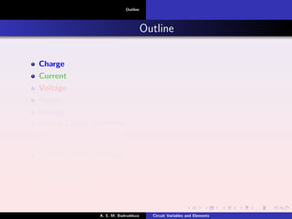
Current[Cntd.]
Direct Current
A direct current (dc) is a current that remains constant with time.
By convention the symbol I is used to represent dc current. The capital
letter I was chosen from the French word for current, intensit´e.
I
t
Fig. 1. Direct current.
A. S. M. Badrudduza Circuit Variables and Elements](https://image.slidesharecdn.com/circuitvariablesandelements-170316193847/85/Circuit-variables-and-elements-16-320.jpg)
![Charge
Current
Voltage
Definition
Direct Current
Alternating Current
Current[Cntd.]
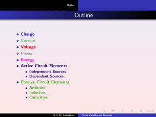
Alternating Current
An alternating current (ac) is a current that varies sinusoidally with time.
By convention the symbol i is used to represent ac current.
i
t0
Fig. 1. Alternating current.
A. S. M. Badrudduza Circuit Variables and Elements](https://image.slidesharecdn.com/circuitvariablesandelements-170316193847/85/Circuit-variables-and-elements-17-320.jpg)

![Charge
Current
Voltage
Definition
Polarity
Voltage[Cntd.]
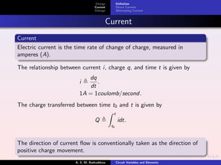
1 The potential at point a with respect to point b is vab.
2 Point a is vab volts above point b and point b is −vab volts above
point a.
3 There is a vab voltage drop from a to b or equivalently a vab voltage
rise from b to a.
4 In general, vab = −vba.
Vab -Vab
a
b
a
b
+
+-
(1) (2)
-
Fig. Voltage polarity.
A. S. M. Badrudduza Circuit Variables and Elements](https://image.slidesharecdn.com/circuitvariablesandelements-170316193847/85/Circuit-variables-and-elements-19-320.jpg)

![Power
Energy
Definition
Problem
Power[Cntd.]
4V 4V
+
-
4V 4V
(3) (4)
+
-
-
+
-
+
(1) (2)
3A 3A3A3A
Fig. Absorbing and supplying power.
In fig. (1) and (2), p = −4 × 3 = −12W .
In fig. (3) and (4), p = 4 × 3 = 12W .
The algebraic sum of the power in a circuit, at any instant of time, is
zero.
p = 0
+Power absorbed = - Power supplied
A. S. M. Badrudduza Circuit Variables and Elements](https://image.slidesharecdn.com/circuitvariablesandelements-170316193847/85/Circuit-variables-and-elements-21-320.jpg)


![Circuit Elements
Active circuit elements
Passive circuit elements
Independent source
Symbols of independent source
Dependent source
Symbols of dependent source
Sources[Cntd]
(3)(1) (2)
+
-
v
+
V
-
i
Fig. Symbol (1) and (2) for independent voltage source where (1) is used
for constant and time varying voltage, (2) is used for constant voltage
and (3) for independent current sources.
A. S. M. Badrudduza Circuit Variables and Elements](https://image.slidesharecdn.com/circuitvariablesandelements-170316193847/85/Circuit-variables-and-elements-25-320.jpg)
![Circuit Elements
Active circuit elements
Passive circuit elements
Independent source
Symbols of independent source
Dependent source
Symbols of dependent source
Sources[Cntd]
Dependent source
An ideal dependent source is an active element in which the source
quantity is controlled by another voltage or current.
Dependent sources are of four kinds:
1 Voltage-controlled voltage source (VCVS)
2 Current-controlled voltage source (CCVS)
3 Voltage-controlled current source (VCCS)
4 Current-controlled current source (CCCS)
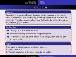
Application
Dependent sources are used for modeling elements such as transistors,
operational amplifiers and integrated circuits.
A. S. M. Badrudduza Circuit Variables and Elements](https://image.slidesharecdn.com/circuitvariablesandelements-170316193847/85/Circuit-variables-and-elements-26-320.jpg)
![Circuit Elements
Active circuit elements
Passive circuit elements
Independent source
Symbols of independent source
Dependent source
Symbols of dependent source
Sources[Cntd.]
Ideal voltage controlled voltage source
The equation for the supplied voltage vs is given by
vs = µvx ,
where vx is the controlling voltage and µ is a multiplying constant that is
dimensionless.
Ideal current controlled voltage source
The equation for the supplied voltage vs is given by
vs = ρix ,
where ix is the controlling current and the multiplying constant, ρ has
the dimension volts per ampere.
A. S. M. Badrudduza Circuit Variables and Elements](https://image.slidesharecdn.com/circuitvariablesandelements-170316193847/85/Circuit-variables-and-elements-27-320.jpg)
![Circuit Elements
Active circuit elements
Passive circuit elements
Independent source
Symbols of independent source
Dependent source
Symbols of dependent source
Sources[Cntd.]
Ideal voltage controlled current source
The equation for the supplied current is is given by
is = αvx ,
where vx is the controlling voltage and the multiplying constant α has a
dimension of ampere per volt.
Ideal current controlled current source
The equation for the supplied current is is given by
is = βix ,
where ix is the controlling current and the multiplying constant, β is
dimensionless.
A. S. M. Badrudduza Circuit Variables and Elements](https://image.slidesharecdn.com/circuitvariablesandelements-170316193847/85/Circuit-variables-and-elements-28-320.jpg)
![Circuit Elements
Active circuit elements
Passive circuit elements
Independent source
Symbols of independent source
Dependent source
Symbols of dependent source
Sources[Cntd.]
xs vv xs iv xs vi xs ii
(a) (b) (c) (d)
+
-
+
-
Fig. Symbol for (a) ideal voltage controlled voltage source , (b) ideal
current controlled voltage source, (c) ideal voltage controlled current
source, (d) ideal current controlled current source.
A. S. M. Badrudduza Circuit Variables and Elements](https://image.slidesharecdn.com/circuitvariablesandelements-170316193847/85/Circuit-variables-and-elements-29-320.jpg)

![Circuit Elements
Active circuit elements
Passive circuit elements
Resistors
Inductors
Capacitors
Resistance[Cntd.]
Fig. Resistance.
Mathematically,
R = ρ
l
A
where,
ρ = Resistivity of the material in ohm-meters
l = Length of the material
A = Area of cross section of the material.
A. S. M. Badrudduza Circuit Variables and Elements](https://image.slidesharecdn.com/circuitvariablesandelements-170316193847/85/Circuit-variables-and-elements-31-320.jpg)
![Circuit Elements
Active circuit elements
Passive circuit elements
Resistors
Inductors
Capacitors
Resistance[Cntd.]
Short Circuit
A short circuit is a circuit element with resistance approaching zero i,e,
R = 0. For a short circuit v = iR = 0.
Open Circuit
An open circuit is a circuit element with resistance approaching infinity
i,e, R = ∞. For an open circuit, i =lim
R→∞
v
R = 0.
Fig. (a) short circuit and (b) open circuit.
A. S. M. Badrudduza Circuit Variables and Elements](https://image.slidesharecdn.com/circuitvariablesandelements-170316193847/85/Circuit-variables-and-elements-32-320.jpg)
![Circuit Elements
Active circuit elements
Passive circuit elements
Resistors
Inductors
Capacitors
Resistance[Cntd.]
Types of Resistors
1. Fixed i,e, their resistance is constant.
2. Variable i,e, their resistance is adjustable. Such as, potentiometer or
pot.
Fig. Symbol for variable resistance.
A. S. M. Badrudduza Circuit Variables and Elements](https://image.slidesharecdn.com/circuitvariablesandelements-170316193847/85/Circuit-variables-and-elements-33-320.jpg)

![Circuit Elements
Active circuit elements
Passive circuit elements
Resistors
Inductors
Capacitors
Inductors[Cntd.]
(a) (b)
Fig. Various inductor configurations (a) solenoidal (b) toroidal.
Types and Configurations
Inductors are of two types: fixed and variable. An inductor may have
different configurations such as solenoidal, toroidal etc.
Inductance
Inductance is the property whereby an inductor exhibits opposition to the
change of current flowing through it, measured in henrys (H).
The inductance of a coil varies directly with the magnetic properties of
the coil. Ferromagnetic materials, therefore, are frequently employed to
increase the inductance by increasing the flux linking the coil.
A. S. M. Badrudduza Circuit Variables and Elements](https://image.slidesharecdn.com/circuitvariablesandelements-170316193847/85/Circuit-variables-and-elements-35-320.jpg)
![Circuit Elements
Active circuit elements
Passive circuit elements
Resistors
Inductors
Capacitors
Inductors[Cntd.]
Fig. A typical inductor.
The inductance of an inductor is given by
L =
N2
µA
l
,
where,
N = Number of turns
µ = Permeability of the core
A = Cross section of the core
l = length of the core
A. S. M. Badrudduza Circuit Variables and Elements](https://image.slidesharecdn.com/circuitvariablesandelements-170316193847/85/Circuit-variables-and-elements-36-320.jpg)
![Circuit Elements
Active circuit elements
Passive circuit elements
Resistors
Inductors
Capacitors
Inductors[Cntd.]
Voltage-current relationship of an inductor is given by
v = L
di
dt
i =
1
L
t
t0
v(t)dt + i(t0)
The power delivered to the inductor is
p = vi = (L
di
dt
)i
The energy stored in the inductor is given by
w =
t
−∞
pdt =
t
−∞
(L
di
dt
)idt = L
i(t)
i(−∞)
idi =
1
2
Li2
A. S. M. Badrudduza Circuit Variables and Elements](https://image.slidesharecdn.com/circuitvariablesandelements-170316193847/85/Circuit-variables-and-elements-37-320.jpg)
![Circuit Elements
Active circuit elements
Passive circuit elements
Resistors
Inductors
Capacitors
Inductors[Cntd.]
When the current through an inductor is not changing with time i,e,
dc current ( di
dt = 0), the voltage across the inductor is zero.Thus,
inductor is an short circuit to dc.
An inductor resists an abrupt change in the current through it. A
discontinuous change in current requires infinite voltage, which is
physically impossible. Conversely, voltage across an inductor can
change instantaneously.
The ideal inductor does not dissipate energy. It takes power from
the circuit when storing energy in its field and returns previously
stored energy when delivering power to the circuit.
A real, non-ideal inductor has a series winding resistance as it is
made of conducting materials, which has some resistance. The
non-ideal inductor also has a winding capacitance which is due to
the capacitive coupling between the conducting coils.
A. S. M. Badrudduza Circuit Variables and Elements](https://image.slidesharecdn.com/circuitvariablesandelements-170316193847/85/Circuit-variables-and-elements-38-320.jpg)
![Circuit Elements
Active circuit elements
Passive circuit elements
Resistors
Inductors
Capacitors
Capacitors[Cntd.]
Fig. A capacitor with applied voltage v.
When a voltage source is connected to the capacitor,the source deposits
a positive charge +q on one plate and a negative charge −q on the
other. The amount of charge stored, represented by q, is directly
proportional to the applied voltage so that
q = Cv,
where, C is known as the capacitance.
Capacitance
Capacitance is the ratio of the charge on one plate of a capacitor to the
voltage difference between the two plates, measured in farads (F).
1farad = 1coulomb/volt
A. S. M. Badrudduza Circuit Variables and Elements](https://image.slidesharecdn.com/circuitvariablesandelements-170316193847/85/Circuit-variables-and-elements-40-320.jpg)
![Circuit Elements
Active circuit elements
Passive circuit elements
Resistors
Inductors
Capacitors
Capacitors[Cntd.]
Fig. A typical capacitor.
For parallel plate capacitor, the capacitance is given by
C =
A
d
,
where,
= Permittivity of the dielectric material between the plates
A = Surface area of each plate
d = Distance between the plates
A. S. M. Badrudduza Circuit Variables and Elements](https://image.slidesharecdn.com/circuitvariablesandelements-170316193847/85/Circuit-variables-and-elements-41-320.jpg)
![Circuit Elements
Active circuit elements
Passive circuit elements
Resistors
Inductors
Capacitors
Capacitors[Cntd.]
Current-voltage relationship of a capacitor is given by
i = C
dv
dt
v =
1
C
t
t0
idt + v(t0)
The instantaneous power delivered to the capacitor is
p = vi = Cv
dv
dt
The energy stored in the capacitor is given by
w =
t
−∞
pdt = C
t
−∞
v
dv
dt
dt = C
v(t)
v(−∞)
vdv =
1
2
Cv2
=
q2
2C
A. S. M. Badrudduza Circuit Variables and Elements](https://image.slidesharecdn.com/circuitvariablesandelements-170316193847/85/Circuit-variables-and-elements-42-320.jpg)
![Circuit Elements
Active circuit elements
Passive circuit elements
Resistors
Inductors
Capacitors
Capacitors[Cntd.]
When the voltage across a capacitor is not changing with time i,e,
dc voltage (dv
dt = 0), the current through the capacitor is zero.Thus,
capacitor is an open circuit to dc.However, if a battery (dc voltage)
is connected across a capacitor, the capacitor charges.
A capacitor resists an abrupt change in the voltage across it. A
discontinuous change in voltage requires infinite current, which is
physically impossible. Conversely, current through a capacitor can
change instantaneously.
The ideal capacitor does not dissipate energy. It takes power from
the circuit when storing energy in its field and returns previously
stored energy when delivering power to the circuit.
A real, non-ideal capacitor has a parallel-model leakage
resistance.The leakage resistance may be as high as 100 MΩ and
can be neglected for most practical applications.
A. S. M. Badrudduza Circuit Variables and Elements](https://image.slidesharecdn.com/circuitvariablesandelements-170316193847/85/Circuit-variables-and-elements-43-320.jpg)


The document provides an overview of electrical circuit variables and elements, including definitions and functions of charge, current, voltage, power, and energy. It categorizes circuit elements into active (like batteries and generators) and passive (like resistors, inductors, and capacitors), detailing their properties and applications. It also discusses the relationships between these variables, such as Ohm's law and the principles governing circuit behavior.


![UNIT-I Final (1)[1].pptfgcvhvjgbjhbjgbjhhvhvhvh](https://cdn.slidesharecdn.com/ss_thumbnails/unit-ifinal11-251129122433-e786871d-thumbnail.jpg?width=640&height=640&fit=bounds)


