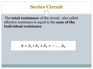
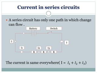
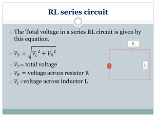
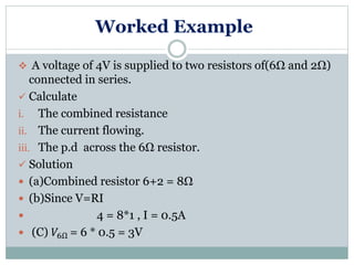
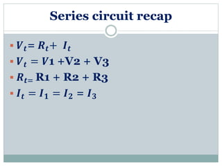
Welcome to our
Presentation
Submitted to
MD. SAYEDUL AREFIN
SERIES CIRCUIT
Topic
Group Members
Name ID
Md. Ariful Islam 162-15-7885
Pritam chandra shil 162-15-7882
Mahe karim 162-15-7770
Md. Aklasur rahaman Robin 162-15-7708
Anirudda Islam 162-15-7696
Rakibul hasan anik 162-15-7735
Electric Circuits
 Closed Circuit
Electric current flows through it.
 Open Circuit
There is a break.
electric current doesn’t flow through it.
Electric Circuits
Series circuit
Parallel
circuit
What is series circuit?
A Series circuit has only one path to group .so
electrons must go through each component to get
back to ground . All loads are placed in series.
Therefore:
I. An open in the circuit will disable the entire
circuit.
II. The current flow is the same throughout circuit.
III. The resistance of each load can be different.
SERIES CIRCUIT IS THE ELECTRICAL
CIRCUIT THAT ARRANGED IN EQUAL
OR SEQUENCE
Series circuit
R1 R2
V
Series Circuit
The total resistance of the circuit , also called
effective resistance is equal to the sum of the
Individual resistance
𝑅 = 𝑅1+ 𝑅2 + 𝑅3 + ⋯ … . . 𝑅 𝑛
Resistors in series
𝑹 𝟏 𝑹 𝟐 𝑹 𝟑
 The total resistance (effective resistance or resultant
resistance) is equal to the sum of the individual
resistance.
𝑹 𝒕𝒐𝒕𝒂𝒍 = 𝑹 𝟏 + 𝑹 𝟐 + 𝑹 𝟑
Current in series circuits
 A series circuit has only one path in which change
can flow .
The current is same everywhere( I = 𝐼1 + 𝐼2 + 𝐼3)
RRR
Battery Switch
I1 I2 I3
I I
The arrangement of bulbs
Bulbs arranged in
series
Dimmer
RL series circuit
o The Total voltage in a series RL circuit is given by
this equation.
o 𝑉𝑇 = 𝑉𝐿
2
+ 𝑉𝑅
2
o 𝑉𝑇= total voltage
o 𝑉𝑅 = voltage across resistor R
o 𝑉𝐿=voltage across inductor L
L
R
Worked Example
 A voltage of 4V is supplied to two resistors of(6Ω and 2Ω)
connected in series.
 Calculate
i. The combined resistance
ii. The current flowing.
iii. The p.d across the 6Ω resistor.
 Solution
 (a)Combined resistor 6+2 = 8Ω
 (b)Since V=RI
 4 = 8*1 , I = 0.5A
 (C) 𝑉6Ω = 6 * 0.5 = 3V
Series circuit Recap
 Electricity must flow trought all
resistors in order to complete the
circuit.
 If a resistor is broken then the circuit
cannot be completed and all aspects
will be work.
Series circuit recap
 𝑽 𝒕= 𝑹 𝒕+ 𝑰 𝒕
 𝑽 𝒕 = 𝑽1 +V2 + V3
 𝑹 𝒕= R1 + R2 + R3
 𝑰 𝒕 = 𝑰 𝟏 = 𝑰 𝟐 = 𝑰 𝟑
Advantages of Series circuits
 Every unit that is connected in a parallel circuit
gets equal amount of voltage.
 It becomes easy to connect or disconnect a new
element without affecting the working of other
elements.
 If any fault happened to the circuit, then also the
current is able to pass through the circuit through
different paths.
Disadvantages of series circuit are
 If one lamp removed (dropped) then
other light go out.
 Flame lights with each other is not as
obvious.
 The farther from the power source
increasingly dim lights.
What is voltage divider rule
 A voltage divider is a simple circuit which
turns a large voltage into a smaller one.
Using just two series resistors and an
input voltage, we can create an
output voltage that is a fraction of the input.
Voltage divider rule
• 𝑽 𝟏 =
𝑹 𝟏
𝑹 𝟏+𝑹 𝟐+𝑹 𝟑
𝑽 𝒔
• 𝑽 𝟐 =
𝑹 𝟐
𝑹 𝟏+𝑹 𝟐+𝑹 𝟑
𝑽 𝒔
• 𝑽 𝟑 =
𝑹 𝟑
𝑹 𝟏+𝑹 𝟐+𝑹 𝟑
𝑽 𝒔
Kirchhoff's Voltage Law (KVL)
 Let's take another look at our example series
circuit, this time numbering the points in the
circuit for voltage reference:
The algebraic sum of all voltages in a
loop must equal zero.
Any Question ??
Thank You !!

Series Circuit

  • 1.
  • 2.
  • 3.
    Group Members Name ID Md.Ariful Islam 162-15-7885 Pritam chandra shil 162-15-7882 Mahe karim 162-15-7770 Md. Aklasur rahaman Robin 162-15-7708 Anirudda Islam 162-15-7696 Rakibul hasan anik 162-15-7735
  • 4.
    Electric Circuits  ClosedCircuit Electric current flows through it.  Open Circuit There is a break. electric current doesn’t flow through it.
  • 5.
  • 6.
    What is seriescircuit? A Series circuit has only one path to group .so electrons must go through each component to get back to ground . All loads are placed in series. Therefore: I. An open in the circuit will disable the entire circuit. II. The current flow is the same throughout circuit. III. The resistance of each load can be different.
  • 7.
    SERIES CIRCUIT ISTHE ELECTRICAL CIRCUIT THAT ARRANGED IN EQUAL OR SEQUENCE Series circuit R1 R2 V
  • 8.
    Series Circuit The totalresistance of the circuit , also called effective resistance is equal to the sum of the Individual resistance 𝑅 = 𝑅1+ 𝑅2 + 𝑅3 + ⋯ … . . 𝑅 𝑛
  • 9.
    Resistors in series 𝑹𝟏 𝑹 𝟐 𝑹 𝟑  The total resistance (effective resistance or resultant resistance) is equal to the sum of the individual resistance. 𝑹 𝒕𝒐𝒕𝒂𝒍 = 𝑹 𝟏 + 𝑹 𝟐 + 𝑹 𝟑
  • 10.
    Current in seriescircuits  A series circuit has only one path in which change can flow . The current is same everywhere( I = 𝐼1 + 𝐼2 + 𝐼3) RRR Battery Switch I1 I2 I3 I I
  • 11.
    The arrangement ofbulbs Bulbs arranged in series Dimmer
  • 12.
    RL series circuit oThe Total voltage in a series RL circuit is given by this equation. o 𝑉𝑇 = 𝑉𝐿 2 + 𝑉𝑅 2 o 𝑉𝑇= total voltage o 𝑉𝑅 = voltage across resistor R o 𝑉𝐿=voltage across inductor L L R
  • 13.
    Worked Example  Avoltage of 4V is supplied to two resistors of(6Ω and 2Ω) connected in series.  Calculate i. The combined resistance ii. The current flowing. iii. The p.d across the 6Ω resistor.  Solution  (a)Combined resistor 6+2 = 8Ω  (b)Since V=RI  4 = 8*1 , I = 0.5A  (C) 𝑉6Ω = 6 * 0.5 = 3V
  • 14.
    Series circuit Recap Electricity must flow trought all resistors in order to complete the circuit.  If a resistor is broken then the circuit cannot be completed and all aspects will be work.
  • 15.
    Series circuit recap 𝑽 𝒕= 𝑹 𝒕+ 𝑰 𝒕  𝑽 𝒕 = 𝑽1 +V2 + V3  𝑹 𝒕= R1 + R2 + R3  𝑰 𝒕 = 𝑰 𝟏 = 𝑰 𝟐 = 𝑰 𝟑
  • 16.
    Advantages of Seriescircuits  Every unit that is connected in a parallel circuit gets equal amount of voltage.  It becomes easy to connect or disconnect a new element without affecting the working of other elements.  If any fault happened to the circuit, then also the current is able to pass through the circuit through different paths.
  • 17.
    Disadvantages of seriescircuit are  If one lamp removed (dropped) then other light go out.  Flame lights with each other is not as obvious.  The farther from the power source increasingly dim lights.
  • 18.
    What is voltagedivider rule  A voltage divider is a simple circuit which turns a large voltage into a smaller one. Using just two series resistors and an input voltage, we can create an output voltage that is a fraction of the input.
  • 19.
    Voltage divider rule •𝑽 𝟏 = 𝑹 𝟏 𝑹 𝟏+𝑹 𝟐+𝑹 𝟑 𝑽 𝒔 • 𝑽 𝟐 = 𝑹 𝟐 𝑹 𝟏+𝑹 𝟐+𝑹 𝟑 𝑽 𝒔 • 𝑽 𝟑 = 𝑹 𝟑 𝑹 𝟏+𝑹 𝟐+𝑹 𝟑 𝑽 𝒔
  • 20.
    Kirchhoff's Voltage Law(KVL)  Let's take another look at our example series circuit, this time numbering the points in the circuit for voltage reference:
  • 21.
    The algebraic sumof all voltages in a loop must equal zero.
  • 22.
  • 23.