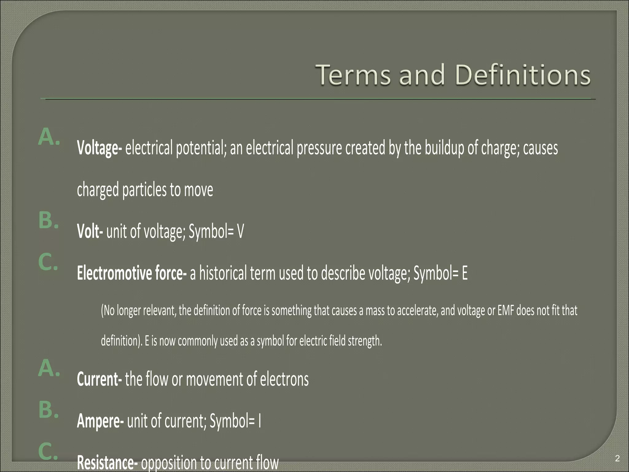
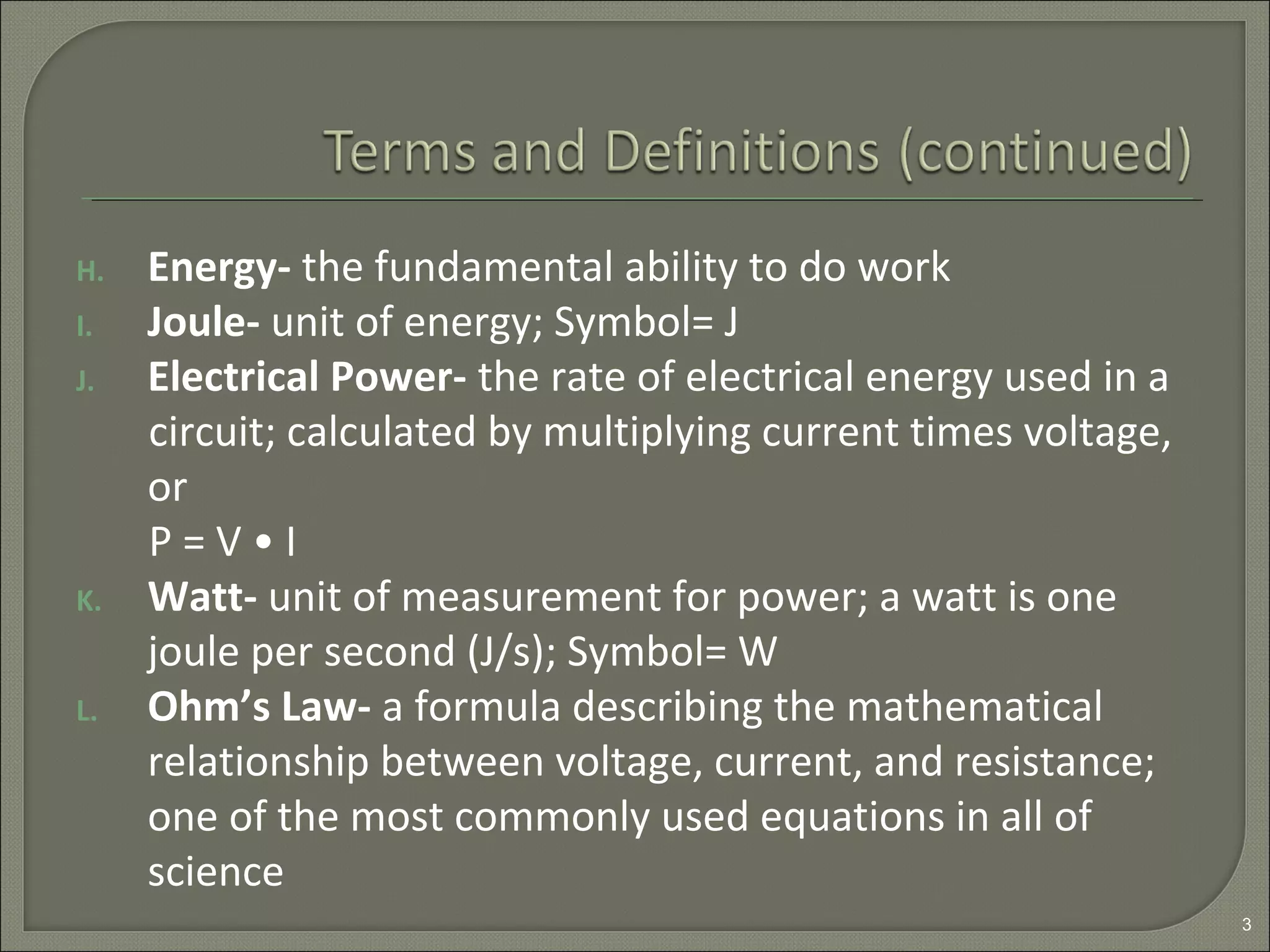
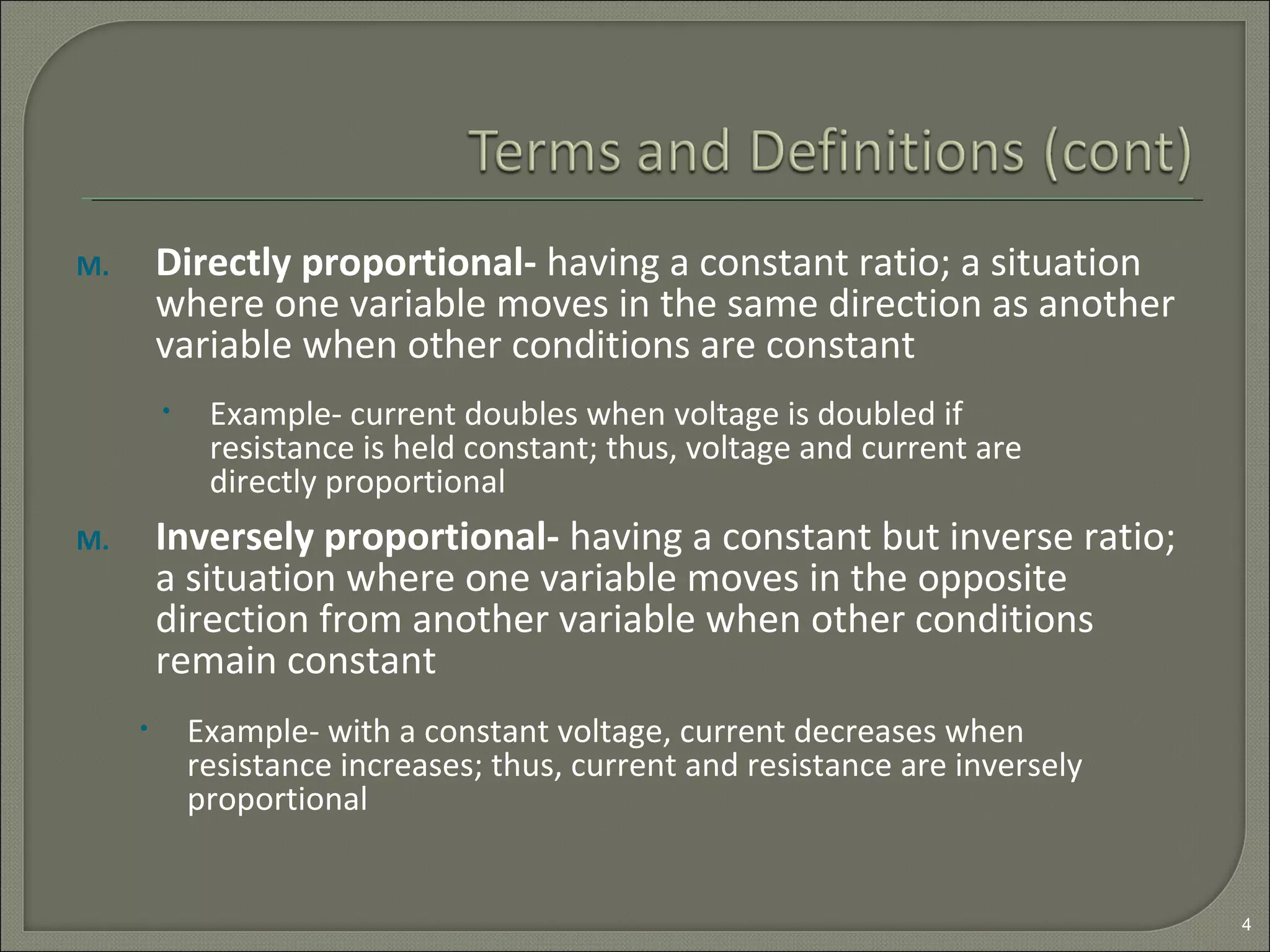
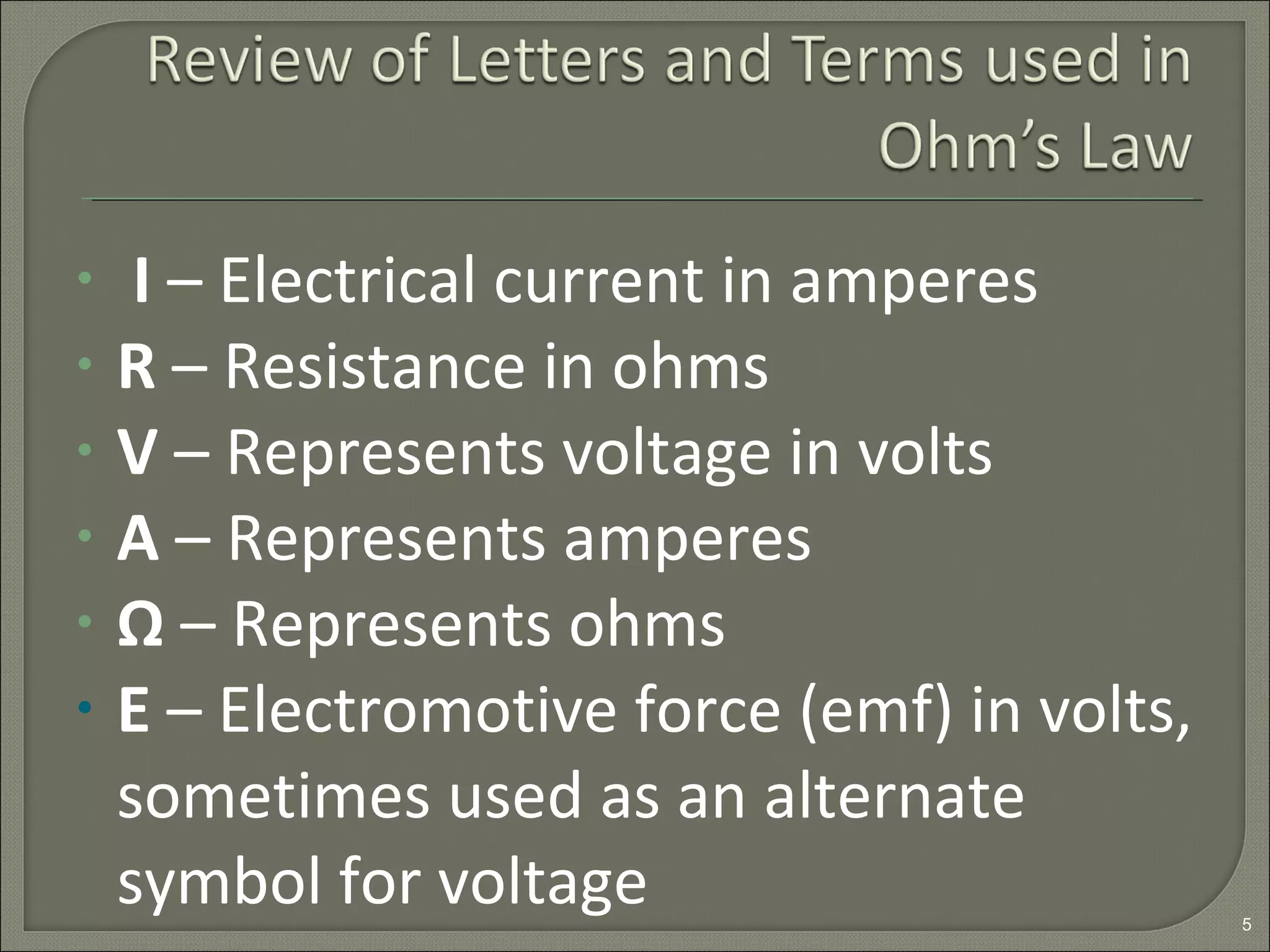
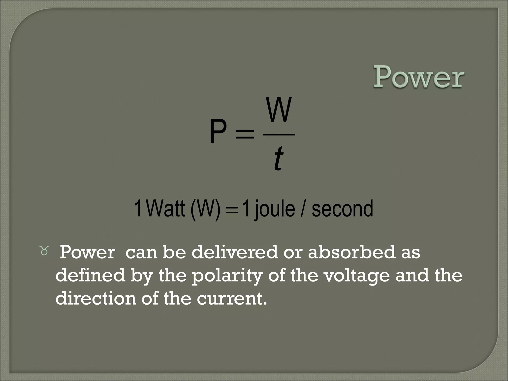
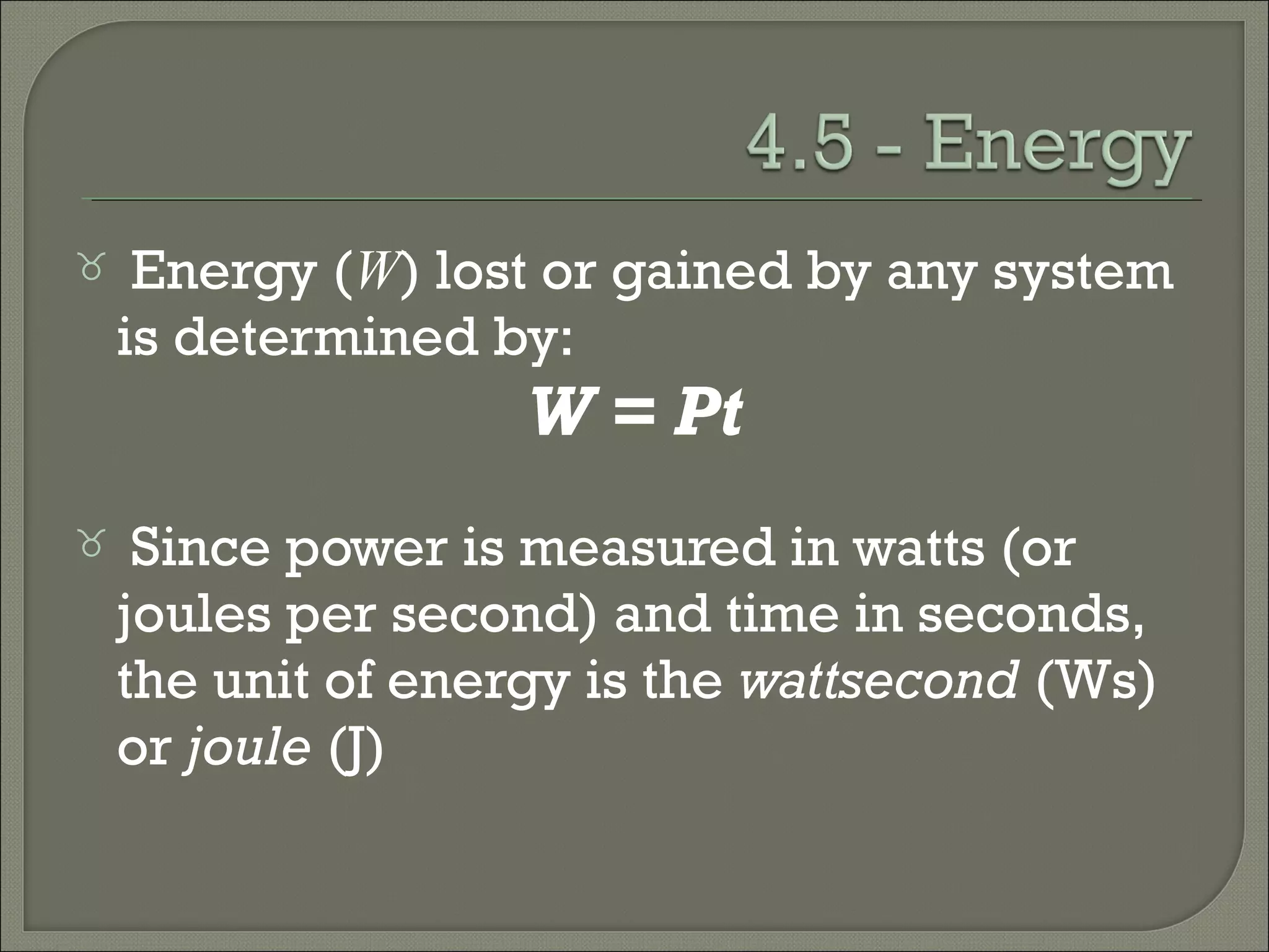
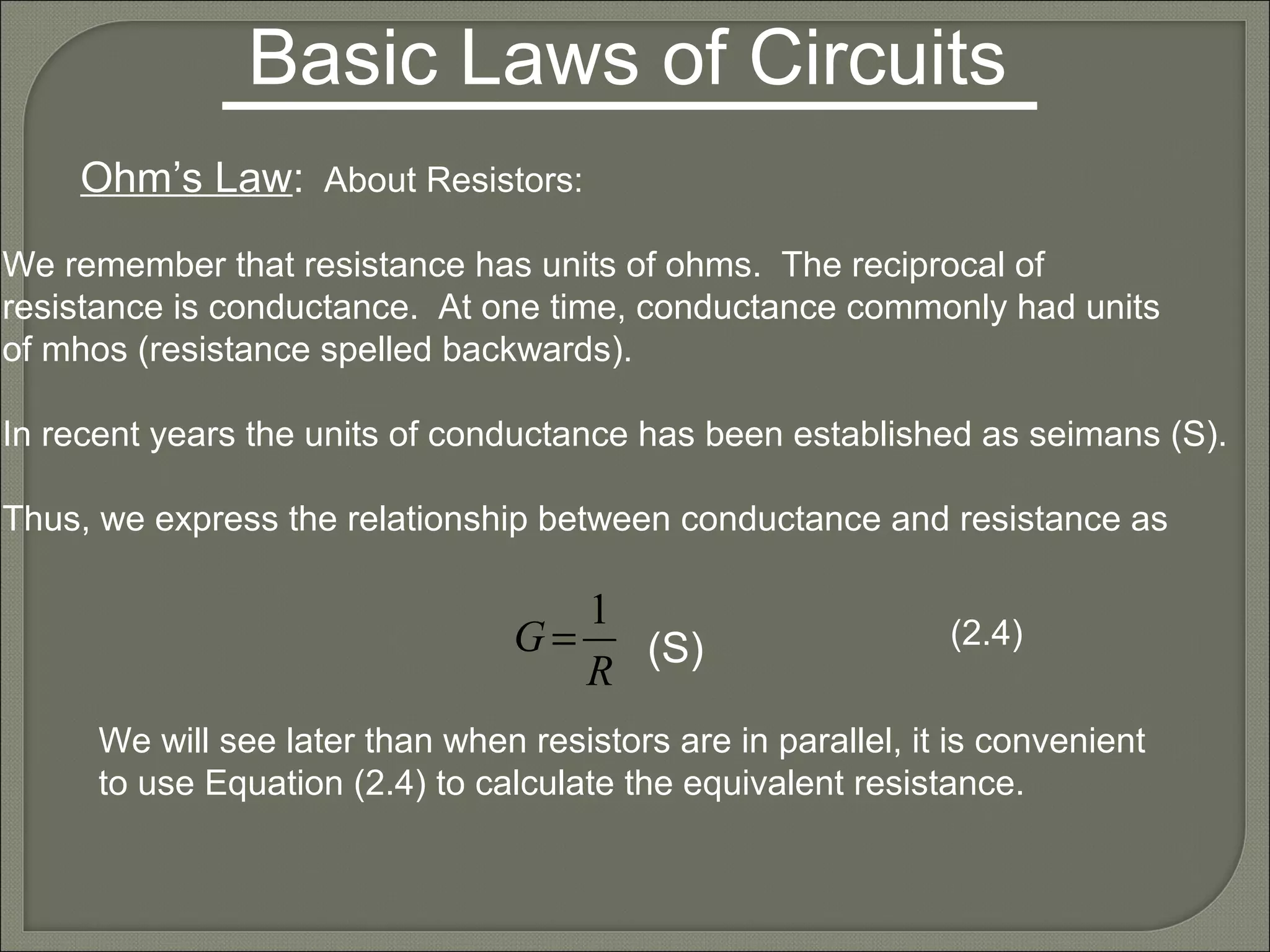
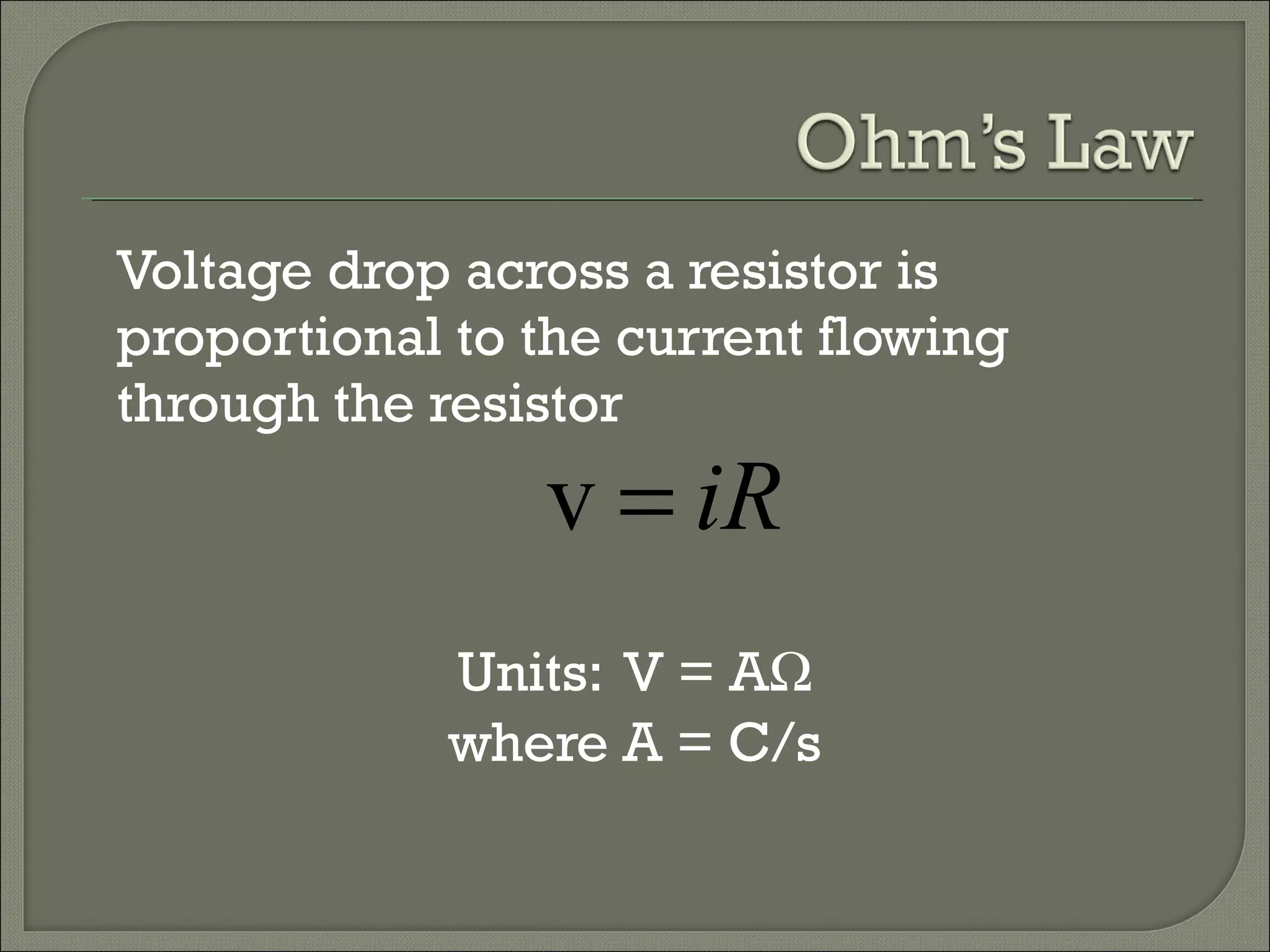
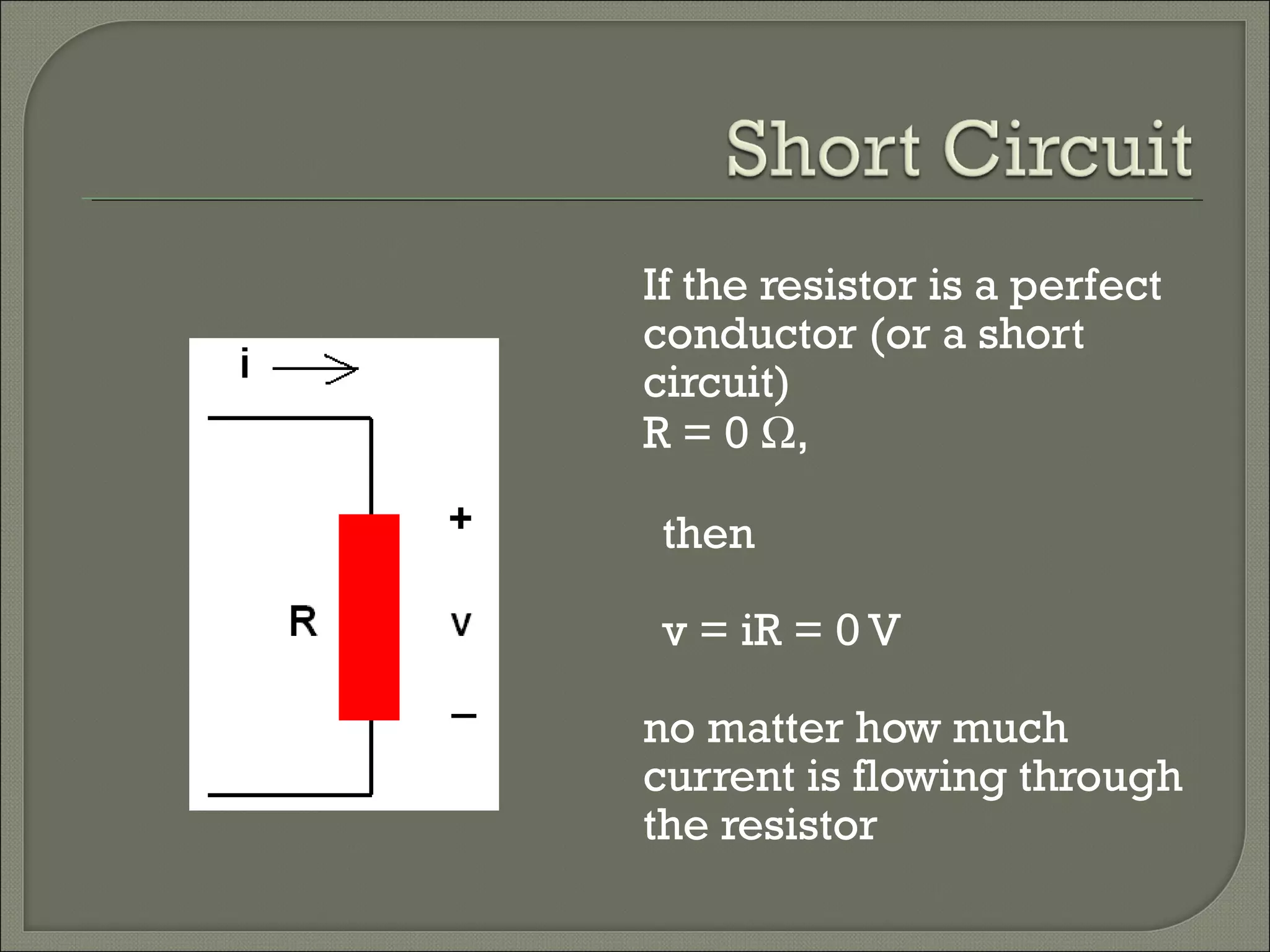
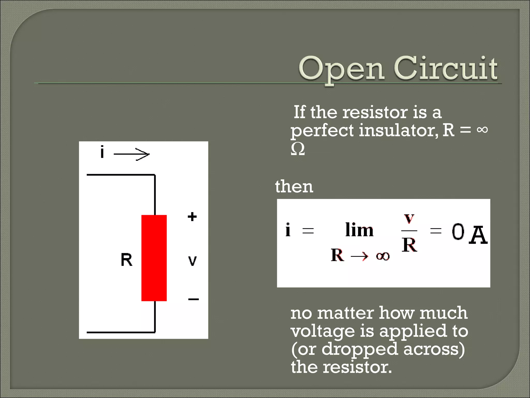
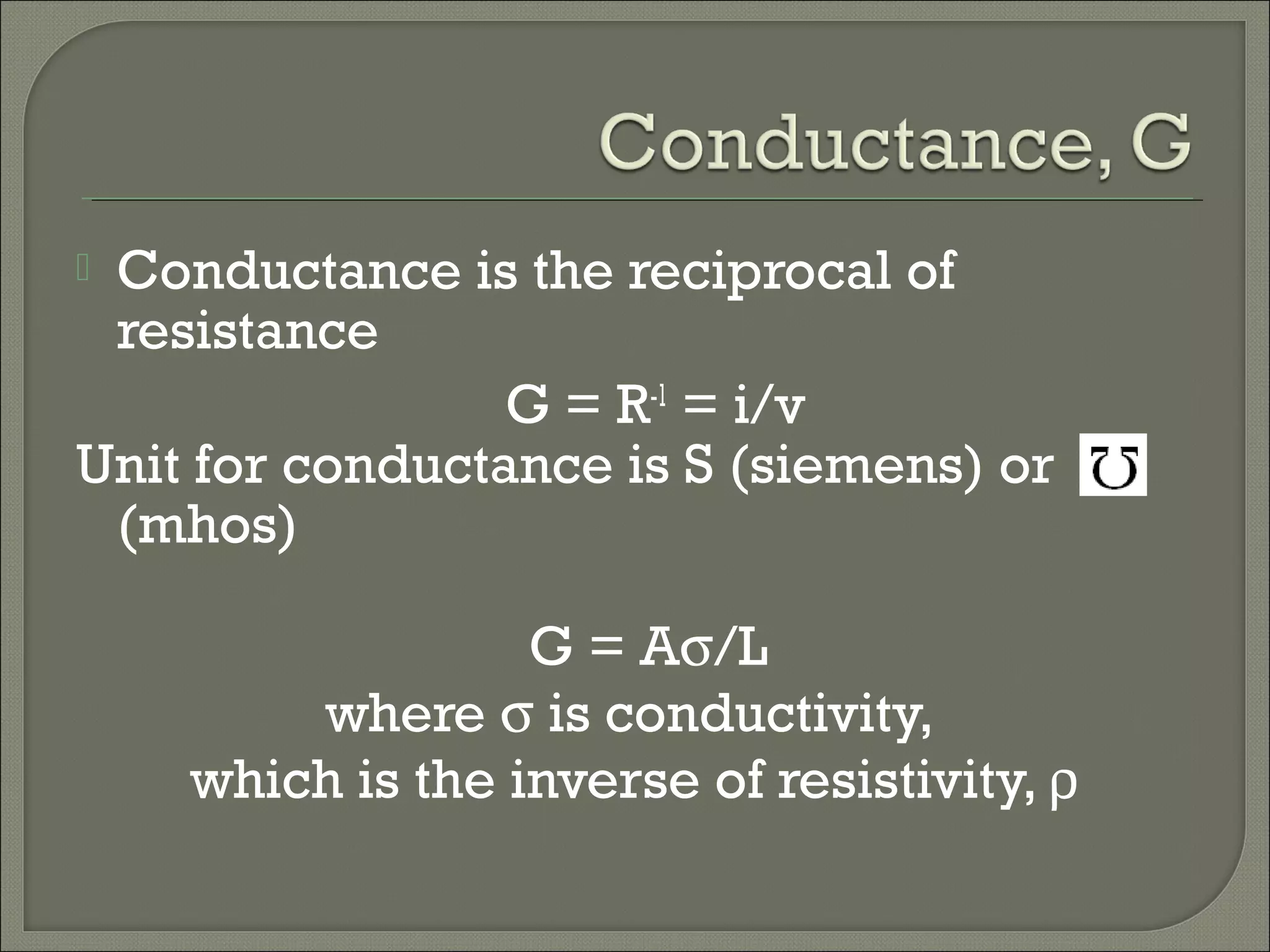
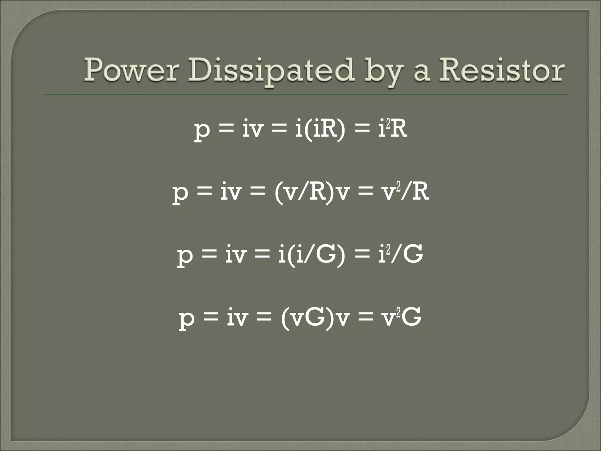
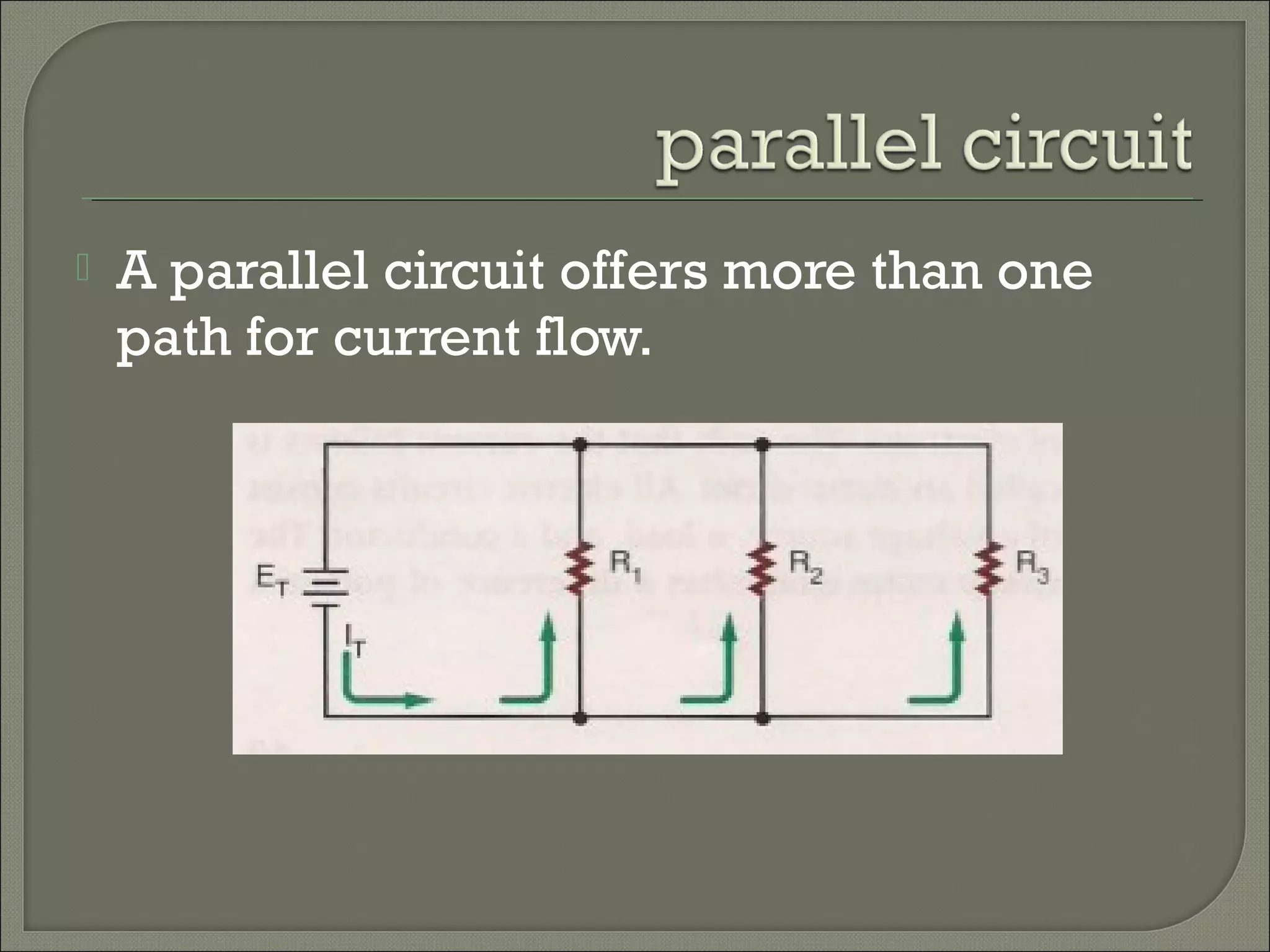
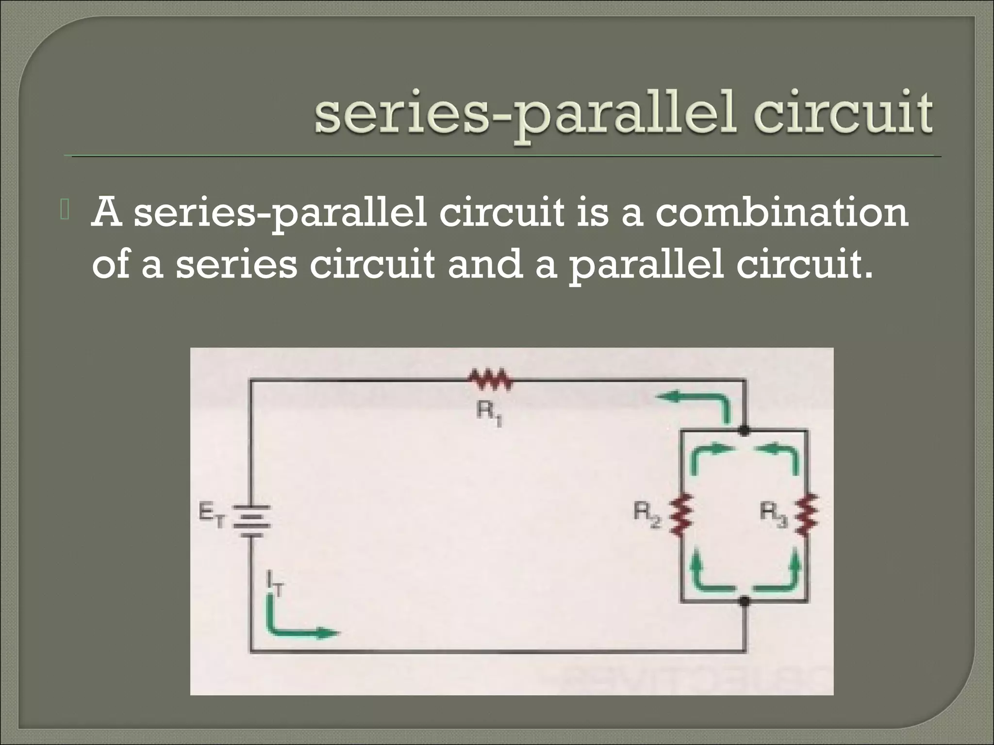
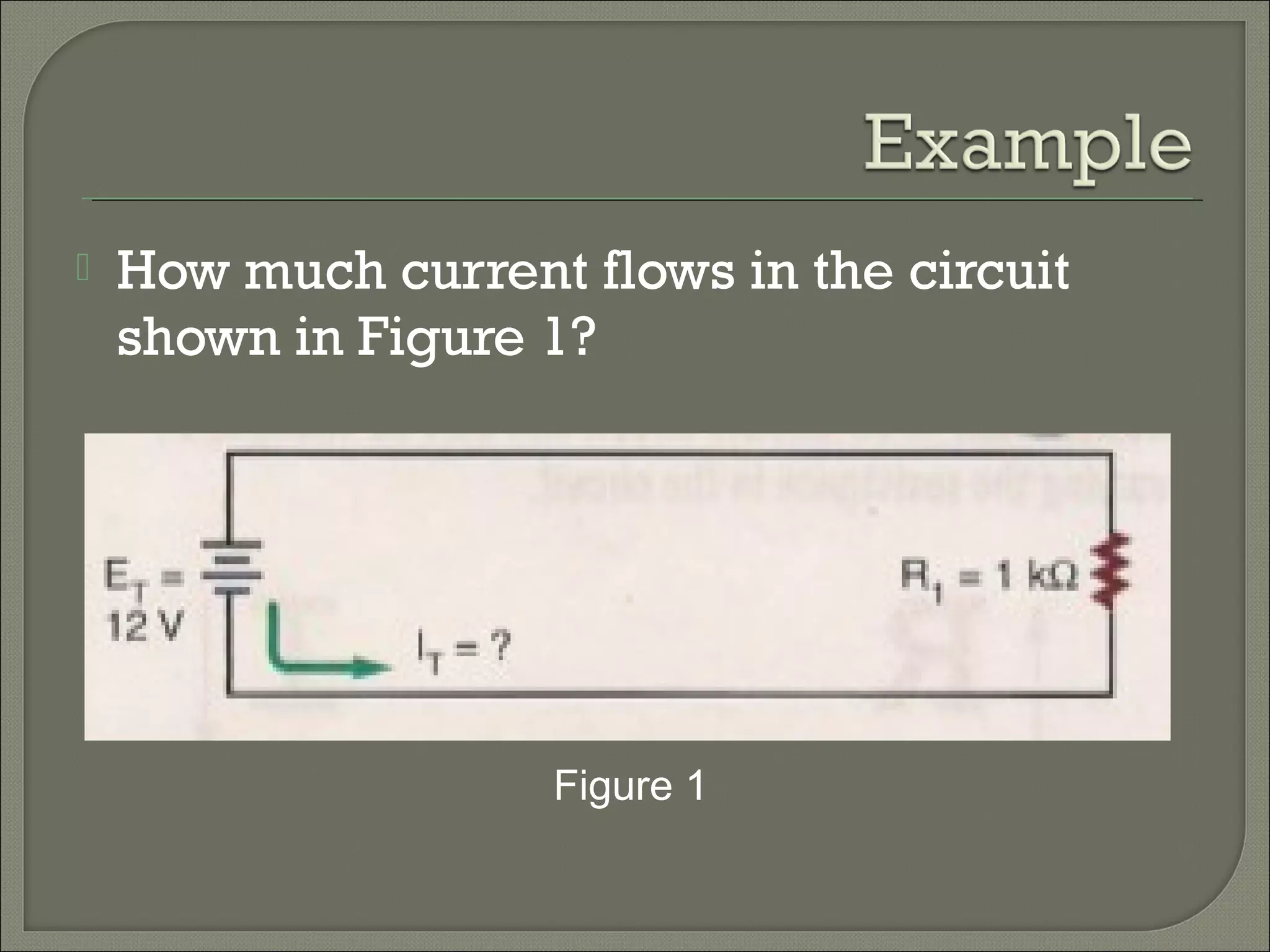
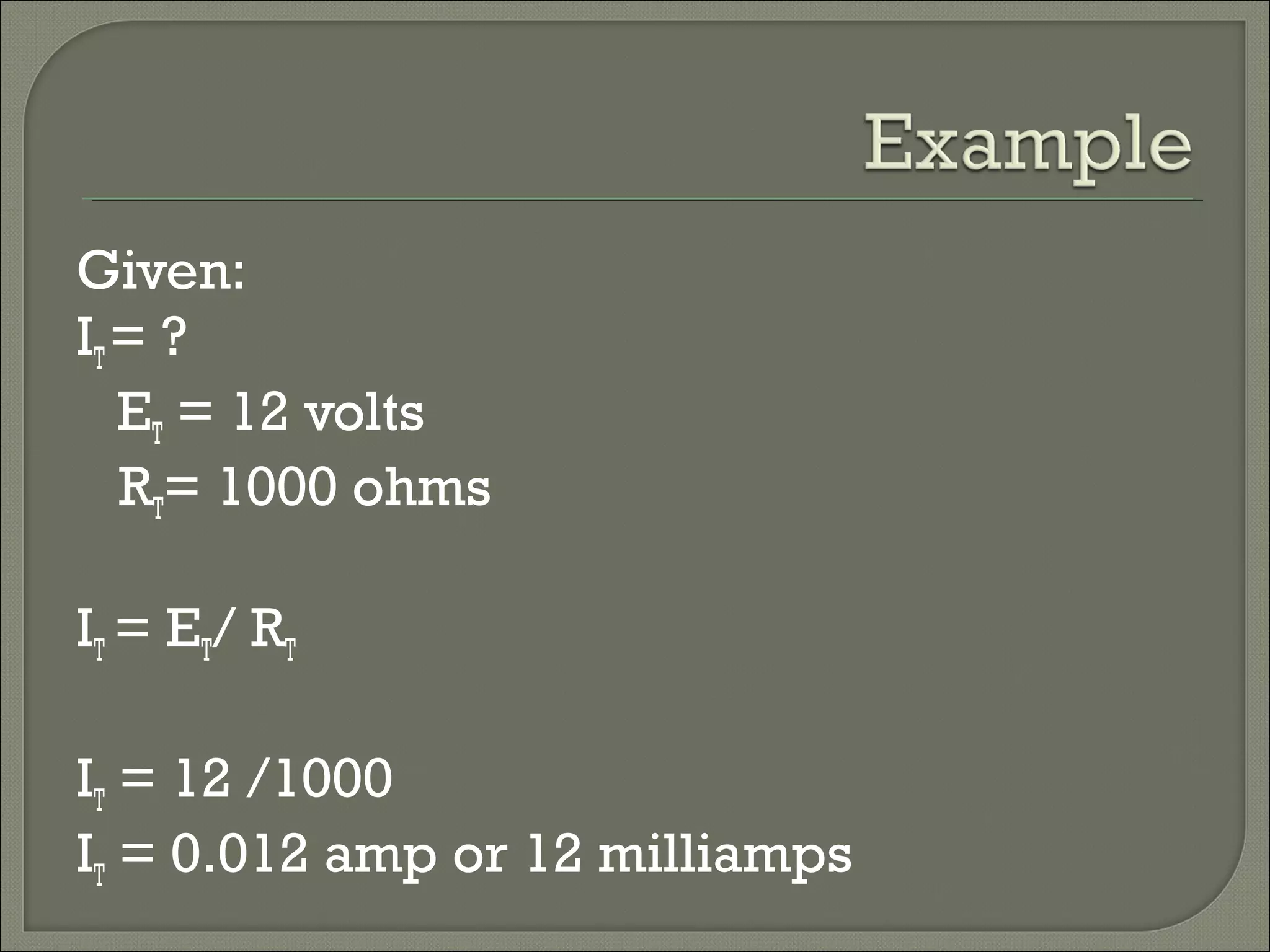
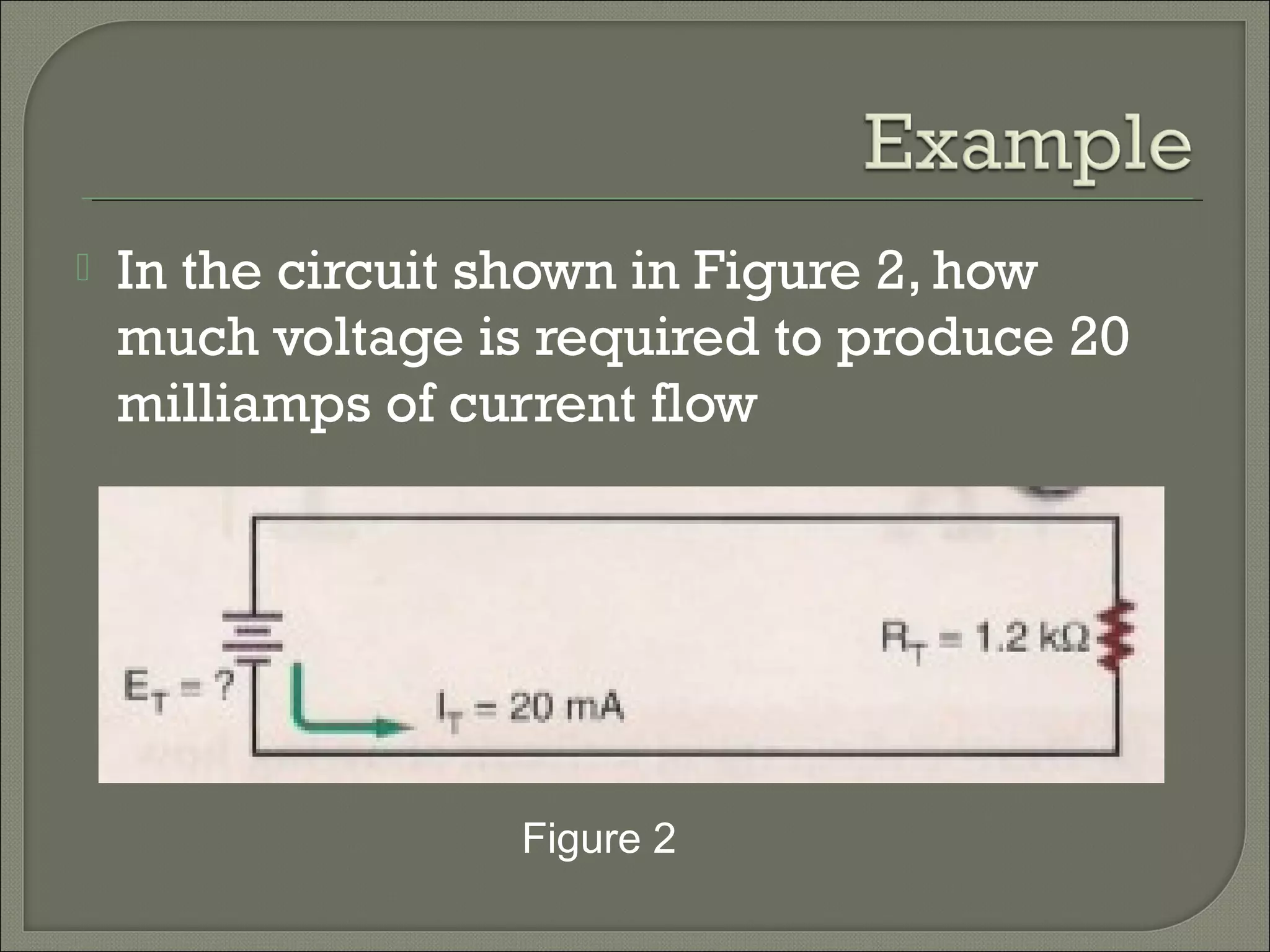
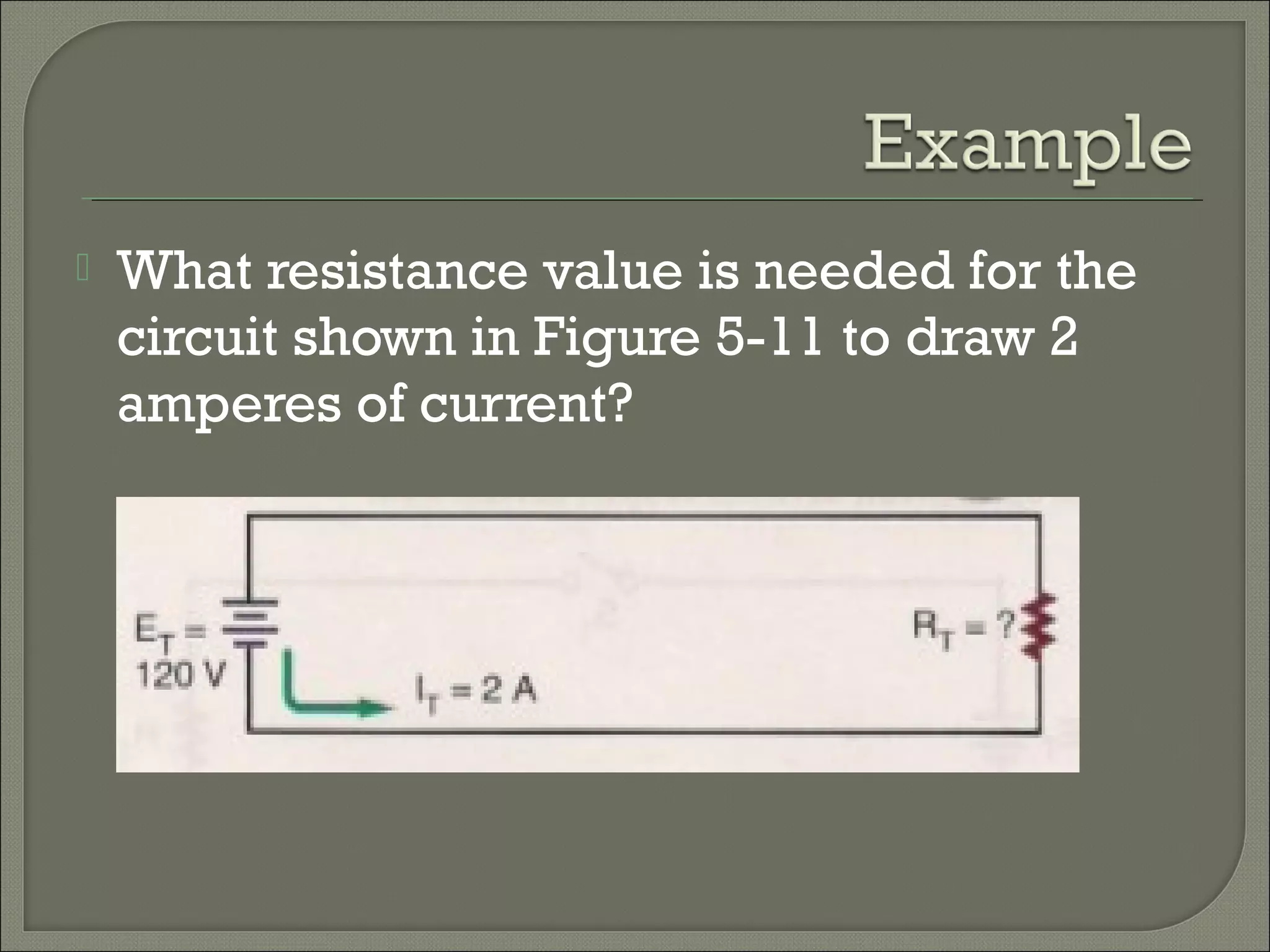
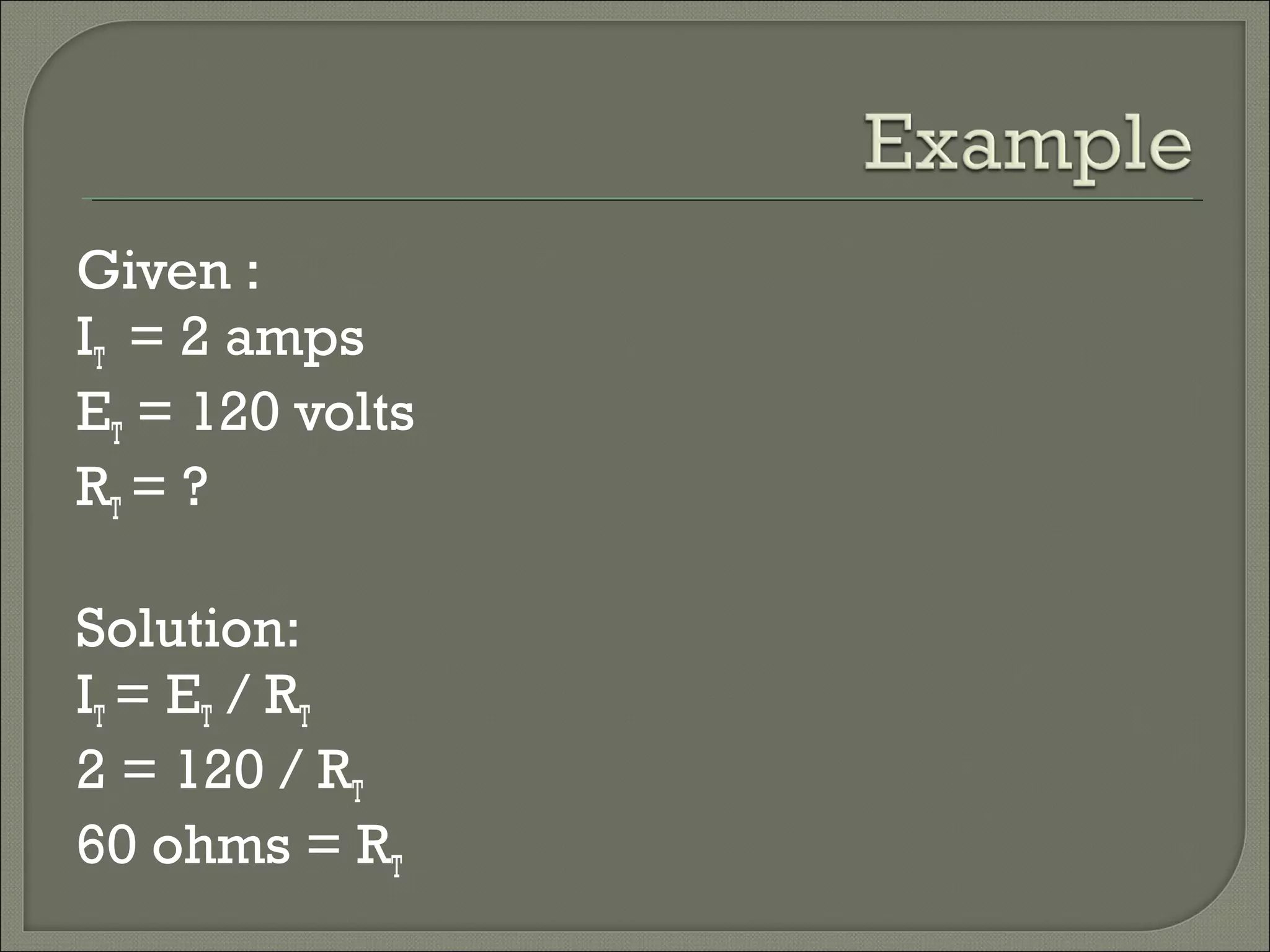
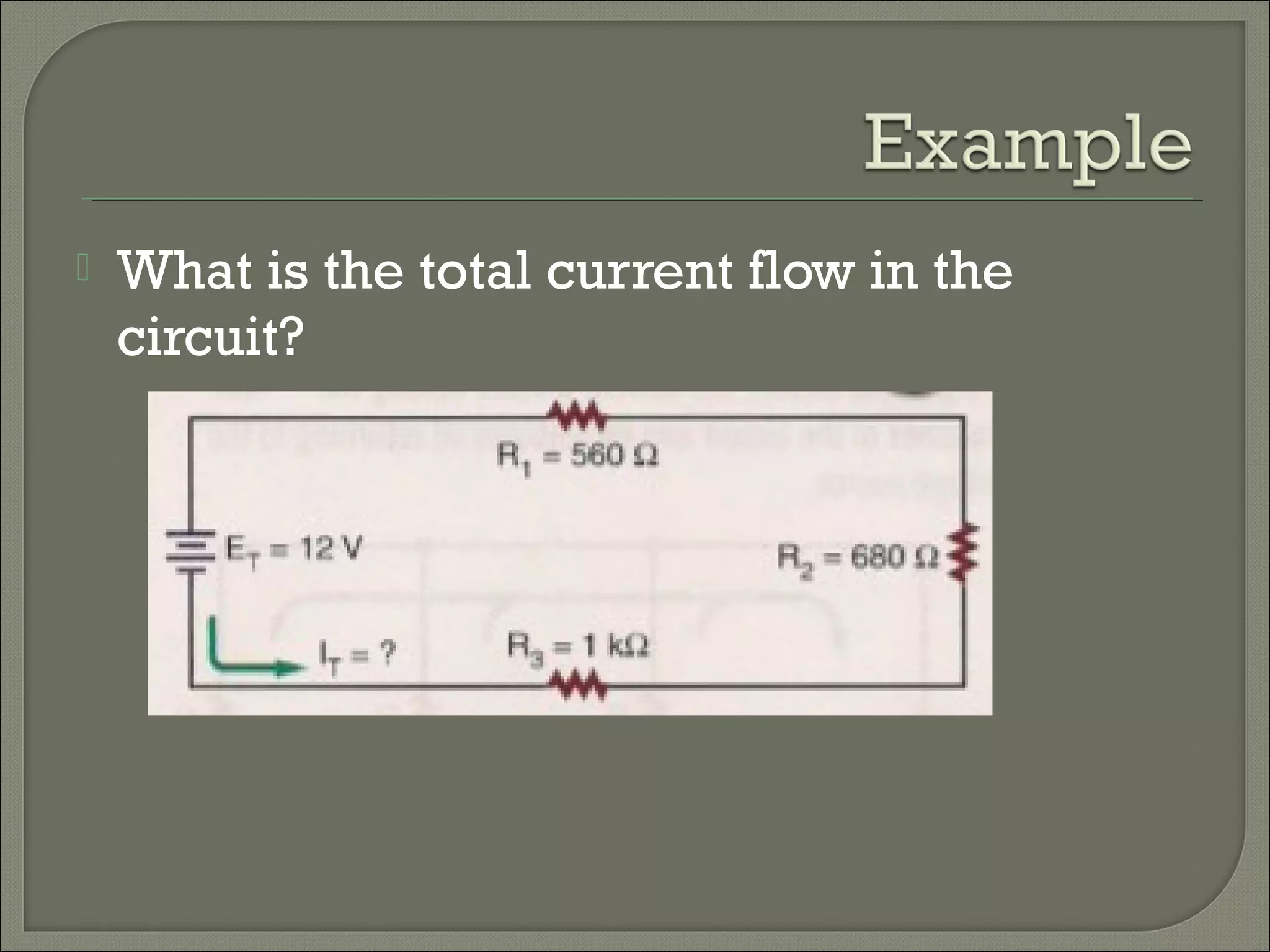
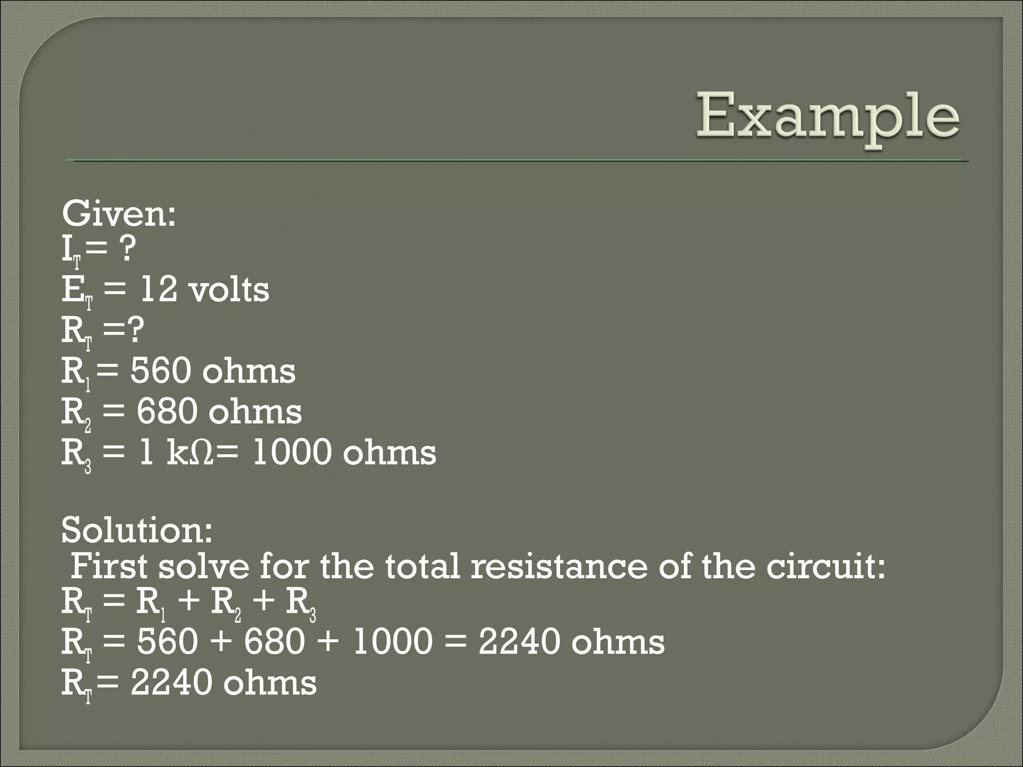
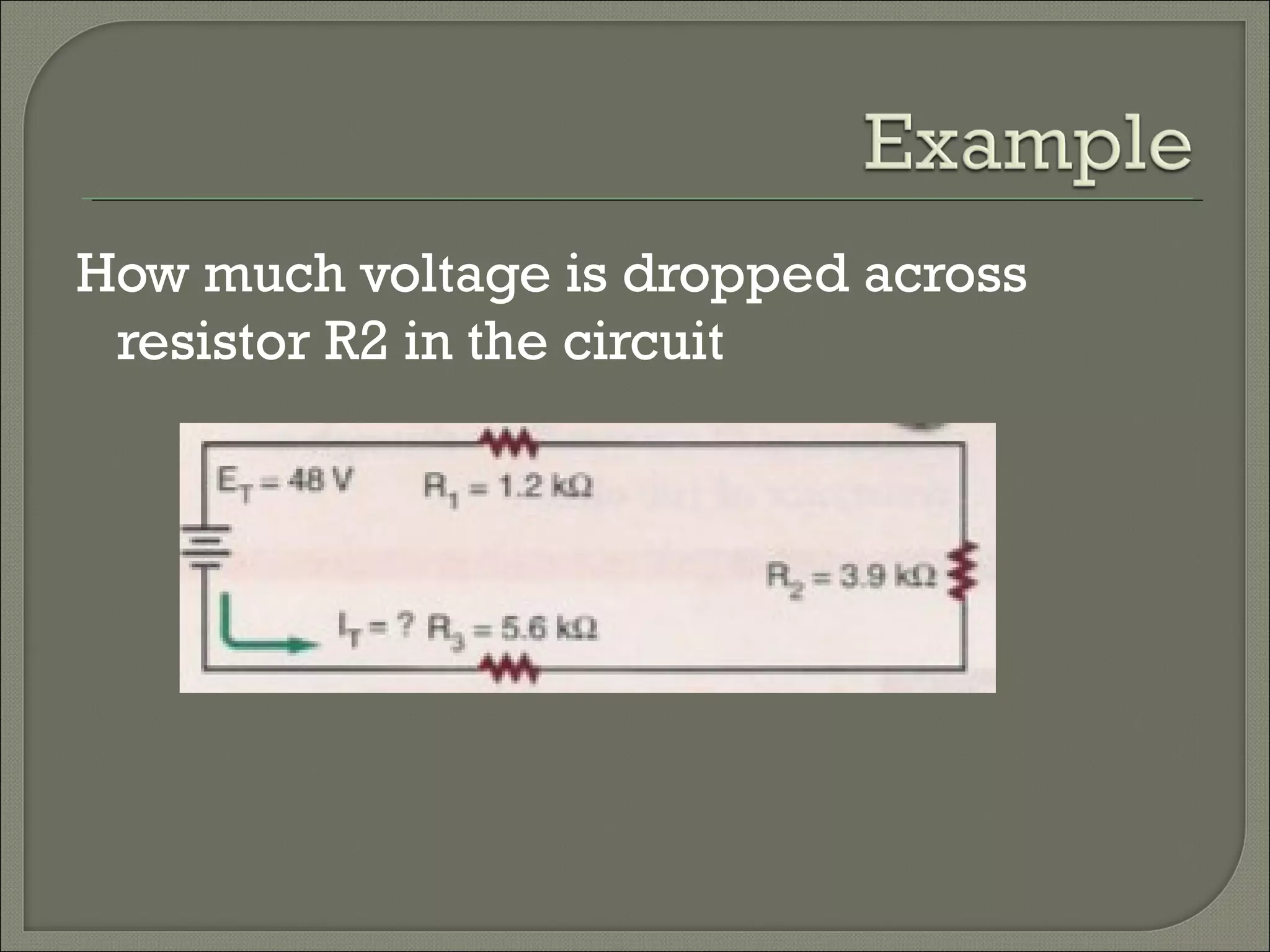
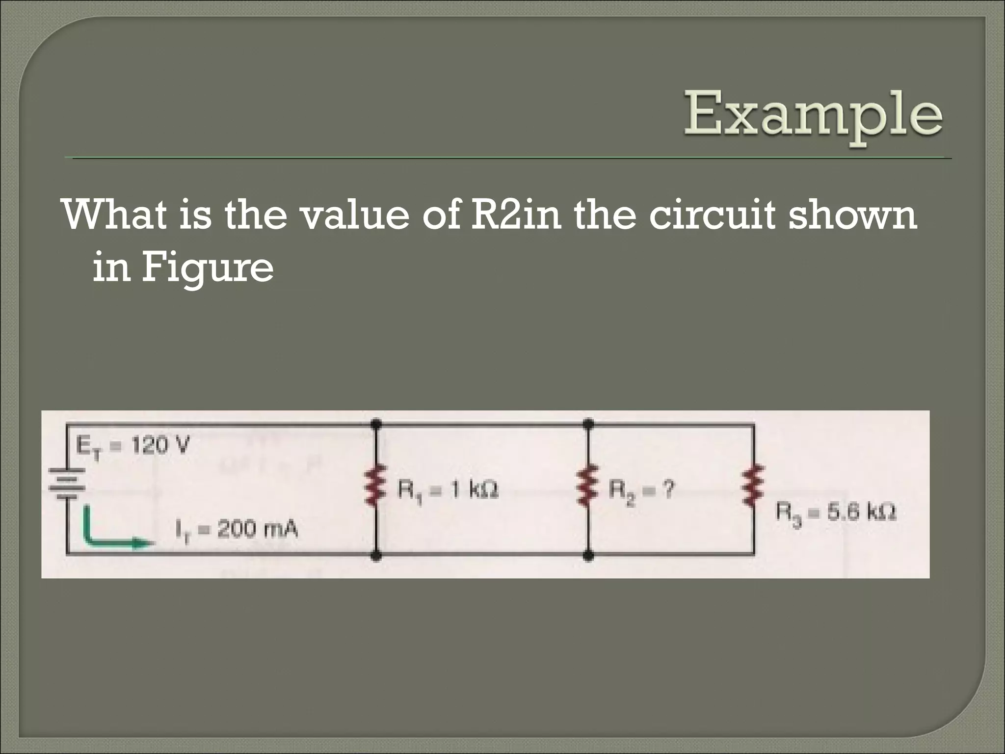
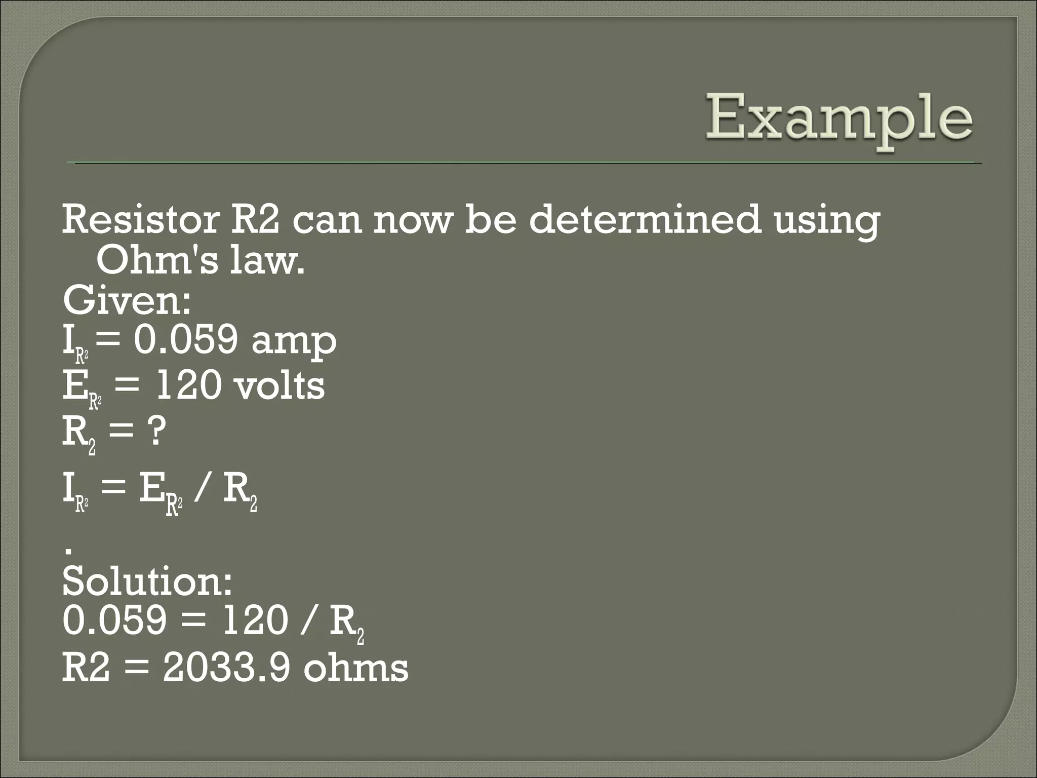
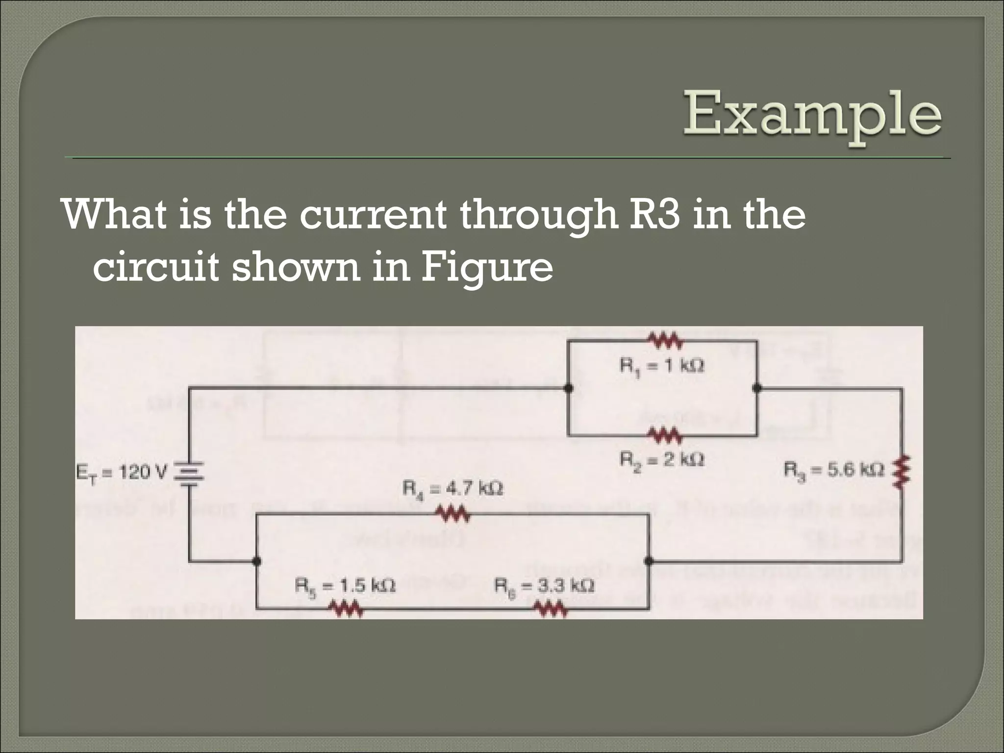
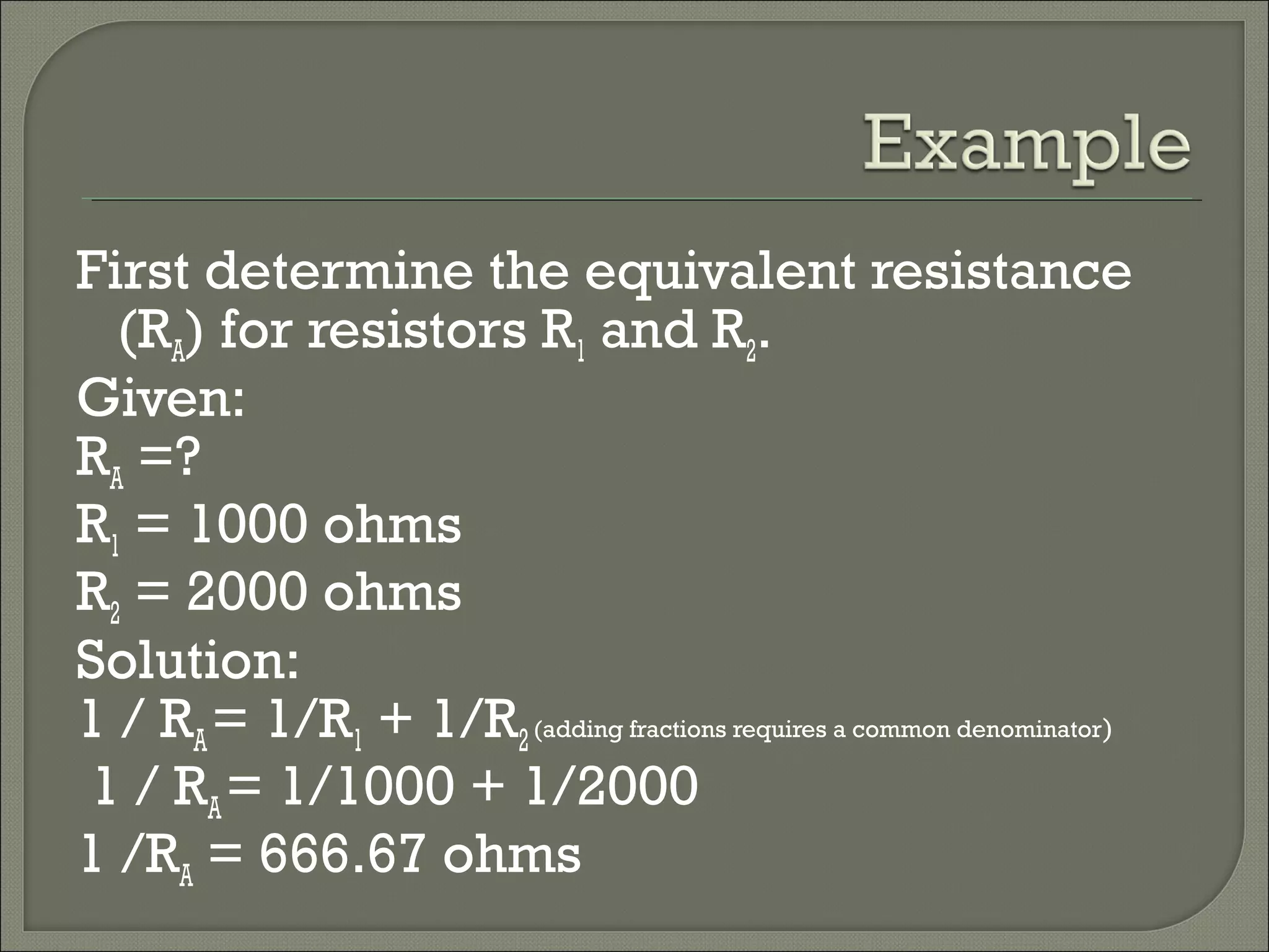
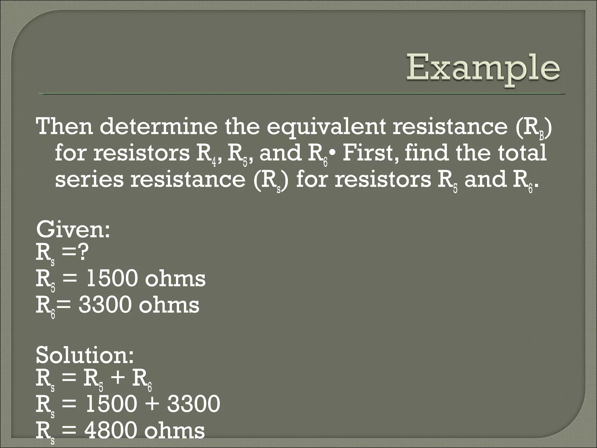
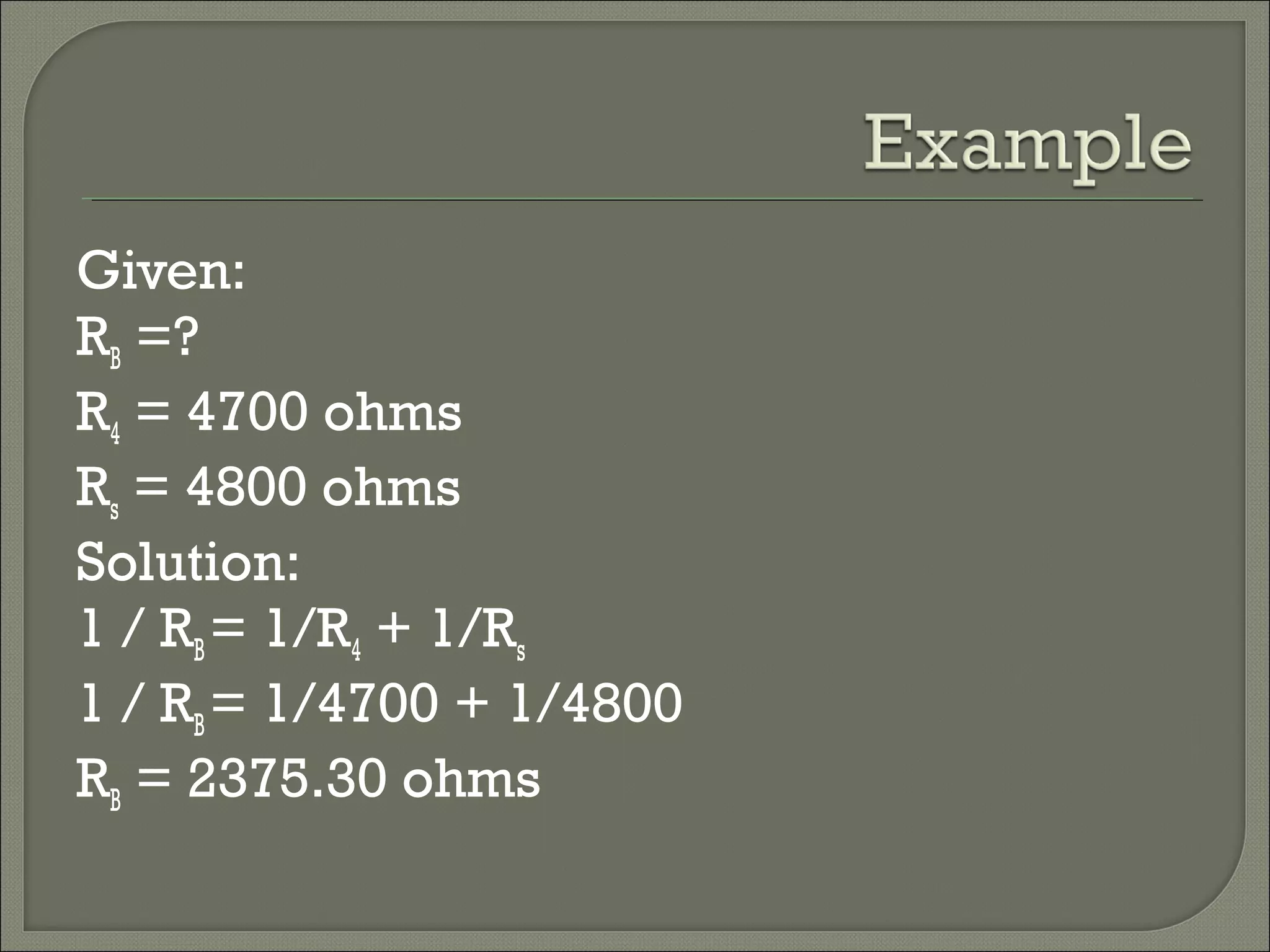
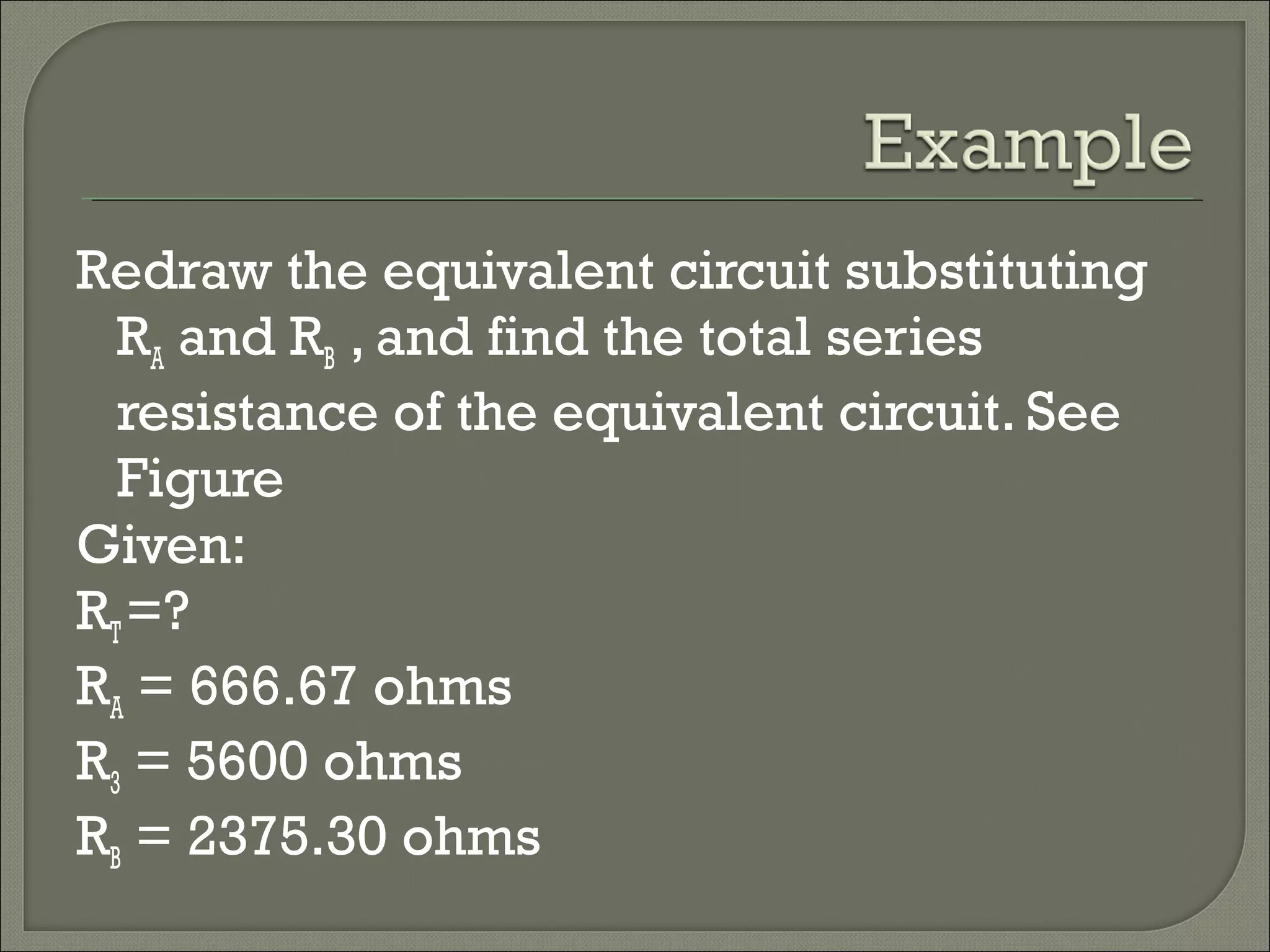
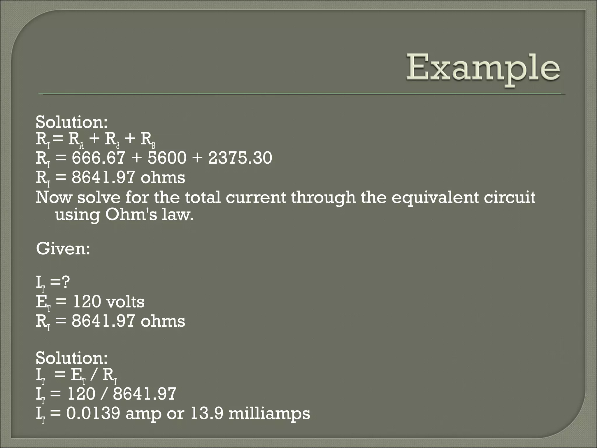
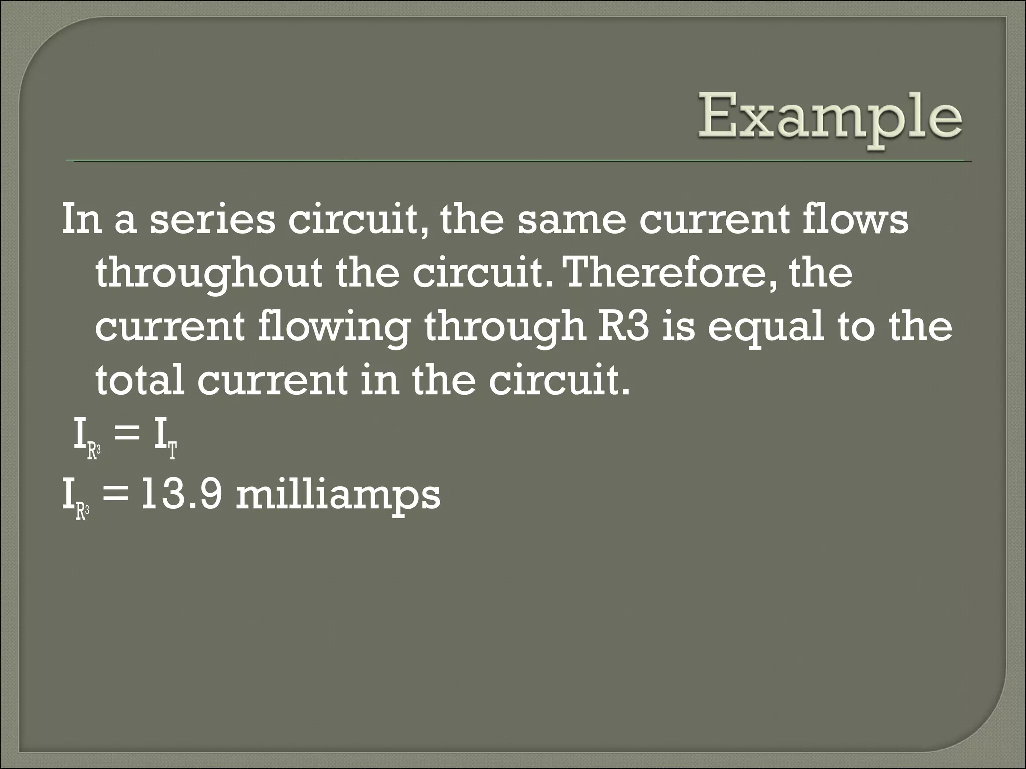
Ohm’s Law & Circuits
2
A. Voltage-electricalpotential;anelectricalpressurecreatedbythebuildupofcharge;causes
chargedparticlestomove
B. Volt-unitofvoltage;Symbol=V
C. Electromotiveforce-ahistoricaltermusedtodescribevoltage;Symbol=E
(Nolongerrelevant,thedefinitionofforceissomethingthatcausesamasstoaccelerate,andvoltageorEMFdoesnotfitthat
definition).Eisnowcommonlyusedasasymbolforelectricfieldstrength.
A. Current-theflowormovementofelectrons
B. Ampere-unitofcurrent;Symbol=I
C. Resistance-oppositiontocurrentflow
H. Energy- the fundamental ability to do work
I. Joule- unit of energy; Symbol= J
J. Electrical Power- the rate of electrical energy used in a
circuit; calculated by multiplying current times voltage,
or
P = V • I
K. Watt- unit of measurement for power; a watt is one
joule per second (J/s); Symbol= W
L. Ohm’s Law- a formula describing the mathematical
relationship between voltage, current, and resistance;
one of the most commonly used equations in all of
science
3
M. Directly proportional- having a constant ratio; a situation
where one variable moves in the same direction as another
variable when other conditions are constant
M. Inversely proportional- having a constant but inverse ratio;
a situation where one variable moves in the opposite
direction from another variable when other conditions
remain constant
4
• Example- current doubles when voltage is doubled if
resistance is held constant; thus, voltage and current are
directly proportional
• Example- with a constant voltage, current decreases when
resistance increases; thus, current and resistance are inversely
proportional
5
• I – Electrical current in amperes
• R – Resistance in ohms
• V – Represents voltage in volts
• A – Represents amperes
• Ω – Represents ohms
• E – Electromotive force (emf) in volts,
sometimes used as an alternate
symbol for voltage
 Power is an indication of how much work
(the conversion of energy from one form
to another) can be done in a specific
amount of time; that is, a rate of doing
work.
 Power can be delivered or absorbed as
defined by the polarity of the voltage and the
direction of the current.
t
W
P =
second/joule1(W)Watt1 =
 Energy (W) lost or gained by any system
is determined by:
W = Pt
 Since power is measured in watts (or
joules per second) and time in seconds,
the unit of energy is the wattsecond (Ws)
or joule (J)
 The watt-second is too small a quantity for
most practical purposes, so the watt-hour
(Wh) and kilowatt-hour (kWh) are defined
as follows:
 The killowatt-hour meter is an instrument
used for measuring the energy supplied to
a residential or commercial user of
electricity.
1000
(h)time(W)power
(kWh)Energy
×
=
(h)time(W)power(Wh)Energy ×=
 Efficiency (η) of a system is determined
by the following equation:
η = Po / Pi
Where: η = efficiency (decimal number)
Po = power output
Pi = power input
 The basic components of a generating (voltage) system
are depicted below, each component has an associated
efficiency, resulting in a loss of power through each
stage.
Insert Fig 4.19Insert Fig 4.19
Insert Table 4.1Insert Table 4.1
Basic Laws of Circuits
Ohm’s Law:
The voltage across a resistor is directly proportional to the current
moving through the resistor.
+ _v ( t )i ( t )
R
v ( t ) = R i ( t )
+_ v ( t )i ( t )
R
v ( t ) = R i ( t )_
(2.1)
(2.2)
Basic Laws of Circuits
Ohm’s Law:
Directly proportional means a straight line relationship.
v(t)
i(t)
R
The resistor is a model and will not produce a straight line
for all conditions of operation.
v(t) = Ri(t)
Basic Laws of Circuits
Ohm’s Law: About Resistors:
The unit of resistance is ohms( Ω).
A mathematical expression for resistance is
l
R
A
ρ=
( )
2
: ( )
: ( )
:
l Thelengthof theconductor meters
A Thecross sectional area meters
Theresistivity mρ
−
Ω ⋅
(2.3)
Basic Laws of Circuits
Ohm’s Law: About Resistors:
We remember that resistance has units of ohms. The reciprocal of
resistance is conductance. At one time, conductance commonly had units
of mhos (resistance spelled backwards).
In recent years the units of conductance has been established as seimans (S).
Thus, we express the relationship between conductance and resistance as
1
G
R
= (2.4)
We will see later than when resistors are in parallel, it is convenient
to use Equation (2.4) to calculate the equivalent resistance.
(S)
Basic Laws of Circuits
Ohm’s Law: Ohm’s Law: Example 2.1.
Consider the following circuit.
+
_
1 1 5 V R M S
( a c )
R
( 1 0 0 W a t t lig h t b u lb )
V
Determine the resistance of the 100 Watt bulb.
2
2
2
2
115
132.25
100
V
P VI I R
R
V
R ohms
P
= = =
= = =
(2.5)
A suggested assignment is to measure the resistance of a 100 watt light
bulb with an ohmmeter. Debate the two answers.
 Resistivity is a material property
• Dependent on the number of free or mobile
charges (usually electrons) in the material.
 In a metal, this is the number of electrons from the
outer shell that are ionized and become part of the
‘sea of electrons’
• Dependent on the mobility of the charges
 Mobility is related to the velocity of the charges.
 It is a function of the material, the frequency and
magnitude of the voltage applied to make the charges
move, and temperature.
Material Resistivity (Ω-cm) Usage
Silver 1.64x10⁻⁸
Conductor
Copper 1.72x10⁻⁸
Conductor
Aluminum 2.8x10⁻⁸
Conductor
Gold 2.45x10⁻⁸
Conductor
Carbon (Graphite) 4x10⁻⁵
Conductor
Germanium 0.47 Semiconductor
Silicon 640 Semiconductor
Paper 1010
Insulator
Mica 5x10¹¹
Insulator
Glass 1012
Insulator
Teflon 3x10¹²
Insulator
mA Milliamp = 0.001 amps
Kilo ohm = 1000 ohmsKΩ
Resistance takes into account the physical
dimensions of the material
where:
L is the length along which
the carriers are moving
A is the cross sectional area
that the free charges move
through.
A
L
R ρ=
Voltage drop across a resistor is
proportional to the current flowing
through the resistor
Units: V = AΩ
where A = C/s
iR=v
Insert Fig 4.8Insert Fig 4.8
If the resistor is a perfect
conductor (or a short
circuit)
R = 0 Ω,
then
v = iR = 0 V
no matter how much
current is flowing through
the resistor
If the resistor is a
perfect insulator, R = ∞
Ω
then
no matter how much
voltage is applied to
(or dropped across)
the resistor.
A
 Conductance is the reciprocal of
resistance
G = R-1
= i/v
Unit for conductance is S (siemens) or
(mhos)
G = Aσ/L
where σ is conductivity,
which is the inverse of resistivity, ρ
p = iv = i(iR) = i2
R
p = iv = (v/R)v = v2
/R
p = iv = i(i/G) = i2
/G
p = iv = (vG)v = v2
G
 Since R and G are always real positive
numbers
• Power dissipated by a resistor is always positive
 The power consumed by the resistor is
not linear with respect to either the
current flowing through the resistor or
the voltage dropped across the resistor
• This power is released as heat. Thus, resistors
get hot as they absorb power (or dissipate
power) from the circuit.
 There is no power dissipated in a short
circuit.
 There is no power dissipated in an open
circuit.
W0)0()V0(v 22
=Ω== Rpsc
W0)()A0(i 22
=Ω∞== Rpoc
 The path that the current follows is called
an electric circuit.
 All electric circuits consist of a voltage
source, a load, and a conductor
 The voltage source establishes a
difference of potential that forces the
current to flow.
 A series circuit offers a single path for
current flow.
 A parallel circuit offers more than one
path for current flow.
 A series-parallel circuit is a combination
of a series circuit and a parallel circuit.
 How much current flows in the circuit
shown in Figure 1?
Figure 1
Given:
IT= ?
ET = 12 volts
RT= 1000 ohms
IT = ET/ RT
IT = 12 /1000
IT = 0.012 amp or 12 milliamps
 In the circuit shown in Figure 2, how
much voltage is required to produce 20
milliamps of current flow
Figure 2
Given:
IT= 20 mA = = 0.02 amp
ET = ?
RT= 1.2 kΩ = ohms
 In the circuit shown in Figure 5-10, how
much voltage is required to produce 20
milliamps of current flow?
Solution:
IT = ET / RT
0.02 = ET / 1200
ET = 24 volts
 What resistance value is needed for the
circuit shown in Figure 5-11 to draw 2
amperes of current?
Given :
IT = 2 amps
ET = 120 volts
RT = ?
Solution:
IT = ET / RT
2 = 120 / RT
60 ohms = RT
 What is the total current flow in the
circuit?
Given:
IT= ?
ET = 12 volts
RT =?
R1= 560 ohms
R2 = 680 ohms
R3 = 1 kΩ= 1000 ohms
Solution:
First solve for the total resistance of the circuit:
RT = R1 + R2 + R3
RT = 560 + 680 + 1000 = 2240 ohms
RT= 2240 ohms
Draw an equivalent circuit. See Figure. Now
solve for the total current flow:
IT = ET / RT
IT = 12 / 2240
IT = 0.0054 amp or 5.4 milliamp
How much voltage is dropped across
resistor R2 in the circuit
Given:
IT =?
ET = 48 volts
RT =?
R1 = 1.2 k Ω = 1200 ohms
R2 = 3.9 k Ω = 3900 ohms
R3 = 5.6 k Ω = 5600 ohms
Solution:
First solve for the total circuit resistance:
RT = R1 + R2 + R3 = 1200 + 3900 + 5600
RT= 10,700 ohms
Draw the equivalent circuit. See Figure. Solve for the total current in the circuit:
IT = ET / RT
IT = 48 / 10,700
I = 0.0045 amp or 4.5 milliamps
Remember, in a series circuit, the same
current flows throughout the circuit.
Therefore, IR = IT
IR2 = ER2 / R2
0.0045 = ER / 3900
ER2 = 17.55 volts
What is the value of R2in the circuit shown
in Figure
 What is the value of R2 in the circuit
shown in Figure?
 First solve for the current that flows
through R1 and R3. Because the voltage is
the same in each branch of a parallel
circuit, each branch voltage is equal to
the source voltage of 120 volts.
Given:
IR1
ER1 = 120 volts
R1 = 1000 ohms
Solution:
IR1 = ER1 / R1
IR1 = 120 / 1000
IR1 = 0.12 amp
Given:
IR3
ER3 = 120 volts
R3 = 5600 ohms
Solution:
IR3 = ER3 / R3
IR3 = 120 / 5600
Circuit, the total current is equal to the sum of
the currents in the branch currents.
Given:
IT = 0.200 amp
IR1= 0.120 amp
IR2=?
IR3= 0.021 amp
Solution:
IT = IR1 + IR2+ IR3
0.200 = 0.120 + IR2 + 0.021
0.200 = 0.141 + IR2
0.200 - 0.141 = IR2
Resistor R2 can now be determined using
Ohm's law.
Given:
IR2 = 0.059 amp
ER2 = 120 volts
R2 = ?
IR2 = ER2 / R2
.
Solution:
0.059 = 120 / R2
R2 = 2033.9 ohms
What is the current through R3 in the
circuit shown in Figure
First determine the equivalent resistance
(RA) for resistors R1 and R2.
Given:
RA =?
R1 = 1000 ohms
R2 = 2000 ohms
Solution:
1 / RA= 1/R1 + 1/R2(adding fractions requires a common denominator)
1 / RA= 1/1000 + 1/2000
1 /RA = 666.67 ohms
Then determine the equivalent resistance (RB)
for resistors R4, R5, and R6• First, find the total
series resistance (Rs) for resistors R5 and R6.
Given:
Rs =?
R5 = 1500 ohms
R6= 3300 ohms
Solution:
Rs = R5 + R6
Rs = 1500 + 3300
Rs = 4800 ohms
Given:
RB =?
R4 = 4700 ohms
Rs = 4800 ohms
Solution:
1 / RB= 1/R4 + 1/Rs
1 / RB= 1/4700 + 1/4800
RB = 2375.30 ohms
Redraw the equivalent circuit substituting
RA and RB , and find the total series
resistance of the equivalent circuit. See
Figure
Given:
RT=?
RA = 666.67 ohms
R3 = 5600 ohms
RB = 2375.30 ohms
Solution:
RT= RA + R3 + RB
RT = 666.67 + 5600 + 2375.30
RT = 8641.97 ohms
Now solve for the total current through the equivalent circuit
using Ohm's law.
Given:
IT =?
ET = 120 volts
RT = 8641.97 ohms
Solution:
IT = ET / RT
IT = 120 / 8641.97
IT = 0.0139 amp or 13.9 milliamps
In a series circuit, the same current flows
throughout the circuit.Therefore, the
current flowing through R3 is equal to the
total current in the circuit.
IR3 = IT
IR3 =13.9 milliamps

ohm's law and circuits

  • 1.
    Ohm’s Law &Circuits
  • 2.
    2 A. Voltage-electricalpotential;anelectricalpressurecreatedbythebuildupofcharge;causes chargedparticlestomove B. Volt-unitofvoltage;Symbol=V C.Electromotiveforce-ahistoricaltermusedtodescribevoltage;Symbol=E (Nolongerrelevant,thedefinitionofforceissomethingthatcausesamasstoaccelerate,andvoltageorEMFdoesnotfitthat definition).Eisnowcommonlyusedasasymbolforelectricfieldstrength. A. Current-theflowormovementofelectrons B. Ampere-unitofcurrent;Symbol=I C. Resistance-oppositiontocurrentflow
  • 3.
    H. Energy- thefundamental ability to do work I. Joule- unit of energy; Symbol= J J. Electrical Power- the rate of electrical energy used in a circuit; calculated by multiplying current times voltage, or P = V • I K. Watt- unit of measurement for power; a watt is one joule per second (J/s); Symbol= W L. Ohm’s Law- a formula describing the mathematical relationship between voltage, current, and resistance; one of the most commonly used equations in all of science 3
  • 4.
    M. Directly proportional-having a constant ratio; a situation where one variable moves in the same direction as another variable when other conditions are constant M. Inversely proportional- having a constant but inverse ratio; a situation where one variable moves in the opposite direction from another variable when other conditions remain constant 4 • Example- current doubles when voltage is doubled if resistance is held constant; thus, voltage and current are directly proportional • Example- with a constant voltage, current decreases when resistance increases; thus, current and resistance are inversely proportional
  • 5.
    5 • I –Electrical current in amperes • R – Resistance in ohms • V – Represents voltage in volts • A – Represents amperes • Ω – Represents ohms • E – Electromotive force (emf) in volts, sometimes used as an alternate symbol for voltage
  • 6.
     Power isan indication of how much work (the conversion of energy from one form to another) can be done in a specific amount of time; that is, a rate of doing work.
  • 7.
     Power canbe delivered or absorbed as defined by the polarity of the voltage and the direction of the current. t W P = second/joule1(W)Watt1 =
  • 8.
     Energy (W)lost or gained by any system is determined by: W = Pt  Since power is measured in watts (or joules per second) and time in seconds, the unit of energy is the wattsecond (Ws) or joule (J)
  • 9.
     The watt-secondis too small a quantity for most practical purposes, so the watt-hour (Wh) and kilowatt-hour (kWh) are defined as follows:  The killowatt-hour meter is an instrument used for measuring the energy supplied to a residential or commercial user of electricity. 1000 (h)time(W)power (kWh)Energy × = (h)time(W)power(Wh)Energy ×=
  • 10.
     Efficiency (η)of a system is determined by the following equation: η = Po / Pi Where: η = efficiency (decimal number) Po = power output Pi = power input
  • 11.
     The basiccomponents of a generating (voltage) system are depicted below, each component has an associated efficiency, resulting in a loss of power through each stage. Insert Fig 4.19Insert Fig 4.19
  • 12.
  • 13.
    Basic Laws ofCircuits Ohm’s Law: The voltage across a resistor is directly proportional to the current moving through the resistor. + _v ( t )i ( t ) R v ( t ) = R i ( t ) +_ v ( t )i ( t ) R v ( t ) = R i ( t )_ (2.1) (2.2)
  • 14.
    Basic Laws ofCircuits Ohm’s Law: Directly proportional means a straight line relationship. v(t) i(t) R The resistor is a model and will not produce a straight line for all conditions of operation. v(t) = Ri(t)
  • 15.
    Basic Laws ofCircuits Ohm’s Law: About Resistors: The unit of resistance is ohms( Ω). A mathematical expression for resistance is l R A ρ= ( ) 2 : ( ) : ( ) : l Thelengthof theconductor meters A Thecross sectional area meters Theresistivity mρ − Ω ⋅ (2.3)
  • 16.
    Basic Laws ofCircuits Ohm’s Law: About Resistors: We remember that resistance has units of ohms. The reciprocal of resistance is conductance. At one time, conductance commonly had units of mhos (resistance spelled backwards). In recent years the units of conductance has been established as seimans (S). Thus, we express the relationship between conductance and resistance as 1 G R = (2.4) We will see later than when resistors are in parallel, it is convenient to use Equation (2.4) to calculate the equivalent resistance. (S)
  • 17.
    Basic Laws ofCircuits Ohm’s Law: Ohm’s Law: Example 2.1. Consider the following circuit. + _ 1 1 5 V R M S ( a c ) R ( 1 0 0 W a t t lig h t b u lb ) V Determine the resistance of the 100 Watt bulb. 2 2 2 2 115 132.25 100 V P VI I R R V R ohms P = = = = = = (2.5) A suggested assignment is to measure the resistance of a 100 watt light bulb with an ohmmeter. Debate the two answers.
  • 18.
     Resistivity isa material property • Dependent on the number of free or mobile charges (usually electrons) in the material.  In a metal, this is the number of electrons from the outer shell that are ionized and become part of the ‘sea of electrons’ • Dependent on the mobility of the charges  Mobility is related to the velocity of the charges.  It is a function of the material, the frequency and magnitude of the voltage applied to make the charges move, and temperature.
  • 19.
    Material Resistivity (Ω-cm)Usage Silver 1.64x10⁻⁸ Conductor Copper 1.72x10⁻⁸ Conductor Aluminum 2.8x10⁻⁸ Conductor Gold 2.45x10⁻⁸ Conductor Carbon (Graphite) 4x10⁻⁵ Conductor Germanium 0.47 Semiconductor Silicon 640 Semiconductor Paper 1010 Insulator Mica 5x10¹¹ Insulator Glass 1012 Insulator Teflon 3x10¹² Insulator
  • 20.
    mA Milliamp =0.001 amps Kilo ohm = 1000 ohmsKΩ
  • 21.
    Resistance takes intoaccount the physical dimensions of the material where: L is the length along which the carriers are moving A is the cross sectional area that the free charges move through. A L R ρ=
  • 22.
    Voltage drop acrossa resistor is proportional to the current flowing through the resistor Units: V = AΩ where A = C/s iR=v
  • 24.
  • 25.
    If the resistoris a perfect conductor (or a short circuit) R = 0 Ω, then v = iR = 0 V no matter how much current is flowing through the resistor
  • 26.
    If the resistoris a perfect insulator, R = ∞ Ω then no matter how much voltage is applied to (or dropped across) the resistor. A
  • 27.
     Conductance isthe reciprocal of resistance G = R-1 = i/v Unit for conductance is S (siemens) or (mhos) G = Aσ/L where σ is conductivity, which is the inverse of resistivity, ρ
  • 28.
    p = iv= i(iR) = i2 R p = iv = (v/R)v = v2 /R p = iv = i(i/G) = i2 /G p = iv = (vG)v = v2 G
  • 29.
     Since Rand G are always real positive numbers • Power dissipated by a resistor is always positive  The power consumed by the resistor is not linear with respect to either the current flowing through the resistor or the voltage dropped across the resistor • This power is released as heat. Thus, resistors get hot as they absorb power (or dissipate power) from the circuit.
  • 30.
     There isno power dissipated in a short circuit.  There is no power dissipated in an open circuit. W0)0()V0(v 22 =Ω== Rpsc W0)()A0(i 22 =Ω∞== Rpoc
  • 31.
     The paththat the current follows is called an electric circuit.  All electric circuits consist of a voltage source, a load, and a conductor  The voltage source establishes a difference of potential that forces the current to flow.
  • 32.
     A seriescircuit offers a single path for current flow.
  • 33.
     A parallelcircuit offers more than one path for current flow.
  • 34.
     A series-parallelcircuit is a combination of a series circuit and a parallel circuit.
  • 35.
     How muchcurrent flows in the circuit shown in Figure 1? Figure 1
  • 36.
    Given: IT= ? ET =12 volts RT= 1000 ohms IT = ET/ RT IT = 12 /1000 IT = 0.012 amp or 12 milliamps
  • 37.
     In thecircuit shown in Figure 2, how much voltage is required to produce 20 milliamps of current flow Figure 2
  • 38.
    Given: IT= 20 mA= = 0.02 amp ET = ? RT= 1.2 kΩ = ohms
  • 39.
     In thecircuit shown in Figure 5-10, how much voltage is required to produce 20 milliamps of current flow?
  • 40.
    Solution: IT = ET/ RT 0.02 = ET / 1200 ET = 24 volts
  • 41.
     What resistancevalue is needed for the circuit shown in Figure 5-11 to draw 2 amperes of current?
  • 42.
    Given : IT =2 amps ET = 120 volts RT = ? Solution: IT = ET / RT 2 = 120 / RT 60 ohms = RT
  • 43.
     What isthe total current flow in the circuit?
  • 44.
    Given: IT= ? ET =12 volts RT =? R1= 560 ohms R2 = 680 ohms R3 = 1 kΩ= 1000 ohms Solution: First solve for the total resistance of the circuit: RT = R1 + R2 + R3 RT = 560 + 680 + 1000 = 2240 ohms RT= 2240 ohms
  • 45.
    Draw an equivalentcircuit. See Figure. Now solve for the total current flow: IT = ET / RT IT = 12 / 2240 IT = 0.0054 amp or 5.4 milliamp
  • 46.
    How much voltageis dropped across resistor R2 in the circuit
  • 47.
    Given: IT =? ET =48 volts RT =? R1 = 1.2 k Ω = 1200 ohms R2 = 3.9 k Ω = 3900 ohms R3 = 5.6 k Ω = 5600 ohms Solution: First solve for the total circuit resistance: RT = R1 + R2 + R3 = 1200 + 3900 + 5600 RT= 10,700 ohms Draw the equivalent circuit. See Figure. Solve for the total current in the circuit: IT = ET / RT IT = 48 / 10,700 I = 0.0045 amp or 4.5 milliamps
  • 48.
    Remember, in aseries circuit, the same current flows throughout the circuit. Therefore, IR = IT IR2 = ER2 / R2 0.0045 = ER / 3900 ER2 = 17.55 volts
  • 49.
    What is thevalue of R2in the circuit shown in Figure
  • 50.
     What isthe value of R2 in the circuit shown in Figure?  First solve for the current that flows through R1 and R3. Because the voltage is the same in each branch of a parallel circuit, each branch voltage is equal to the source voltage of 120 volts.
  • 51.
    Given: IR1 ER1 = 120volts R1 = 1000 ohms Solution: IR1 = ER1 / R1 IR1 = 120 / 1000 IR1 = 0.12 amp Given: IR3 ER3 = 120 volts R3 = 5600 ohms Solution: IR3 = ER3 / R3 IR3 = 120 / 5600
  • 52.
    Circuit, the totalcurrent is equal to the sum of the currents in the branch currents. Given: IT = 0.200 amp IR1= 0.120 amp IR2=? IR3= 0.021 amp Solution: IT = IR1 + IR2+ IR3 0.200 = 0.120 + IR2 + 0.021 0.200 = 0.141 + IR2 0.200 - 0.141 = IR2
  • 53.
    Resistor R2 cannow be determined using Ohm's law. Given: IR2 = 0.059 amp ER2 = 120 volts R2 = ? IR2 = ER2 / R2 . Solution: 0.059 = 120 / R2 R2 = 2033.9 ohms
  • 54.
    What is thecurrent through R3 in the circuit shown in Figure
  • 55.
    First determine theequivalent resistance (RA) for resistors R1 and R2. Given: RA =? R1 = 1000 ohms R2 = 2000 ohms Solution: 1 / RA= 1/R1 + 1/R2(adding fractions requires a common denominator) 1 / RA= 1/1000 + 1/2000 1 /RA = 666.67 ohms
  • 56.
    Then determine theequivalent resistance (RB) for resistors R4, R5, and R6• First, find the total series resistance (Rs) for resistors R5 and R6. Given: Rs =? R5 = 1500 ohms R6= 3300 ohms Solution: Rs = R5 + R6 Rs = 1500 + 3300 Rs = 4800 ohms
  • 57.
    Given: RB =? R4 =4700 ohms Rs = 4800 ohms Solution: 1 / RB= 1/R4 + 1/Rs 1 / RB= 1/4700 + 1/4800 RB = 2375.30 ohms
  • 58.
    Redraw the equivalentcircuit substituting RA and RB , and find the total series resistance of the equivalent circuit. See Figure Given: RT=? RA = 666.67 ohms R3 = 5600 ohms RB = 2375.30 ohms
  • 59.
    Solution: RT= RA +R3 + RB RT = 666.67 + 5600 + 2375.30 RT = 8641.97 ohms Now solve for the total current through the equivalent circuit using Ohm's law. Given: IT =? ET = 120 volts RT = 8641.97 ohms Solution: IT = ET / RT IT = 120 / 8641.97 IT = 0.0139 amp or 13.9 milliamps
  • 60.
    In a seriescircuit, the same current flows throughout the circuit.Therefore, the current flowing through R3 is equal to the total current in the circuit. IR3 = IT IR3 =13.9 milliamps

Editor's Notes

  • #3 The scientific units for voltage are joule per coulomb. The scientific units for current are coulombs per second.
  • #25 Put Fig 4.9 in and the Equations 4.5 and 4.7