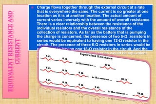
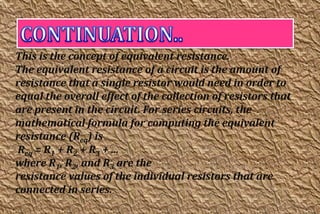
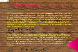
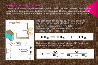
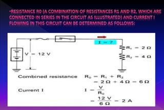
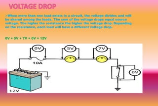
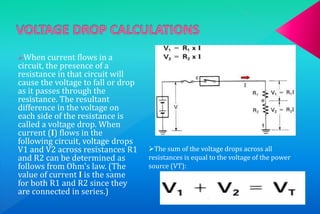
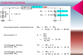
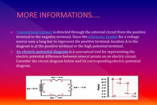
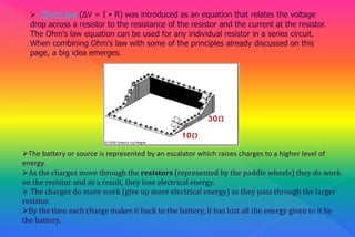
 SERIES CIRCUITS 
A series circuit is the simplest 
circuit. The conductors, control and 
protection devices, loads, and 
power source are connected with 
only one path to ground for current 
flow. The resistance of each device 
can be different. The same amount 
of current will flow through each. 
The voltage across each will be 
different. If the path is broken, no 
current flows and no part of the 
circuit works. Christmas tree lights 
are a good example; when one light 
goes out the entire string stops 
working.
 A Series Circuit has only one path to ground, so 
electrons must go through each component to get 
back to ground. All loads are placed in series. 
 Therefore: 
 1. An open in the circuit will disable the entire circuit. 
 2. The voltage divides (shared) between the loads. 
 3. The current flow is the same throughout the circuit. 
 4. The resistance of each load can be different.
 Charge flows together through the external circuit at a rate 
that is everywhere the same. The current is no greater at one 
location as it is at another location. The actual amount of 
current varies inversely with the amount of overall resistance. 
There is a clear relationship between the resistance of the 
individual resistors and the overall resistance of the 
collection of resistors. As far as the battery that is pumping 
the charge is concerned, the presence of two 6-Ω ;resistors in 
series would be equivalent to having one 12-Ω resistor in the 
circuit. The presence of three 6-Ω resistors in series would be 
equivalent to having one 18-Ω resistor in the circuit. And the 
presence of four 6-Ω resistors in series would be equivalent 
to having one 24-Ω resistor in the circuit.
This is the concept of equivalent resistance. 
The equivalent resistance of a circuit is the amount of 
resistance that a single resistor would need in order to 
equal the overall effect of the collection of resistors that 
are present in the circuit. For series circuits, the 
mathematical formula for computing the equivalent 
resistance (Req) is 
Req = R1 + R2 + R3 + ... 
where R1, R2, and R3 are the 
resistance values of the individual resistors that are 
connected in series.
20, 15, 10 5parallel 
More Practice 
Make, solve and check your own problems by using the Equivalent Resistance . The current 
in a series circuit is everywhere the same. Charge does NOT pile up and begin to accumulate at 
any given location such that the current at one location is more than at other locations. Charge 
does NOT become used up by resistors such that there is less of it at one location compared to 
another. The charges can be thought of as marching together through the wires of an electric 
circuit, everywhere marching at the same rate. Current - the rate at which charge flows - is 
everywhere the same. It is the same at the first resistor as it is at the last resistor as it is in the 
battery. Mathematically, one might write
SERIES CIRCUIT CALCULATIONS 
If, for example, two or more lamps (resistances R1 and R2, etc.) are connected in a circuit as 
follows, there is only one route that the current can take. This type of connection is called a 
series connection. The value of current I is always the same at any point in a series circuit. 
The combined resistance RO in this circuit is 
equal to the sum of individual resistance R1 
and R2. In other words: The total 
resistance(RO) is equal to the sum of all 
resistances (R1 + R2 + R3 + .......) 
Therefore, the strength of current (I) flowing in 
the circuit can be found as follows:
When more than one load exists in a circuit, the voltage divides and will 
be shared among the loads. The sum of the voltage drops equal source 
voltage. The higher the resistance the higher the voltage drop. Depending 
on the resistance, each load will have a different voltage drop. 
0V + 5V + 7V + 0V = 12V
When current flows in a 
circuit, the presence of a 
resistance in that circuit will 
cause the voltage to fall or drop 
as it passes through the 
resistance. The resultant 
difference in the voltage on 
each side of the resistance is 
called a voltage drop. When 
current (I) flows in the 
following circuit, voltage drops 
V1 and V2 across resistances R1 
and R2 can be determined as 
follows from Ohm's law. (The 
value of current I is the same 
for both R1 and R2 since they 
are connected in series.) 
The sum of the voltage drops across all 
resistances is equal to the voltage of the power 
source (VT):
 Conventional current is directed through the external circuit from the positive 
terminal to the negative terminal. Since the schematic symbol for a voltage 
source uses a long bar to represent the positive terminal, location A in the 
diagram is at the positive terminal or the high potential terminal. 
 An electric potential diagram is a conceptual tool for representing the 
electric potential difference between several points on an electric circuit. 
Consider the circuit diagram below and its corresponding electric potential 
diagram.
 Ohm's law (ΔV = I • R) was introduced as an equation that relates the voltage 
drop across a resistor to the resistance of the resistor and the current at the resistor. 
The Ohm's law equation can be used for any individual resistor in a series circuit. 
When combining Ohm's law with some of the principles already discussed on this 
page, a big idea emerges. 
The battery or source is represented by an escalator which raises charges to a higher level of 
energy. 
As the charges move through the resistors (represented by the paddle wheels) they do work 
on the resistor and as a result, they lose electrical energy. 
 The charges do more work (give up more electrical energy) as they pass through the larger 
resistor. 
By the time each charge makes it back to the battery, it has lost all the energy given to it by 
the battery.
Series circuit
Series circuit

Series circuit

  • 2.
     SERIES CIRCUITS A series circuit is the simplest circuit. The conductors, control and protection devices, loads, and power source are connected with only one path to ground for current flow. The resistance of each device can be different. The same amount of current will flow through each. The voltage across each will be different. If the path is broken, no current flows and no part of the circuit works. Christmas tree lights are a good example; when one light goes out the entire string stops working.
  • 3.
     A SeriesCircuit has only one path to ground, so electrons must go through each component to get back to ground. All loads are placed in series.  Therefore:  1. An open in the circuit will disable the entire circuit.  2. The voltage divides (shared) between the loads.  3. The current flow is the same throughout the circuit.  4. The resistance of each load can be different.
  • 4.
     Charge flowstogether through the external circuit at a rate that is everywhere the same. The current is no greater at one location as it is at another location. The actual amount of current varies inversely with the amount of overall resistance. There is a clear relationship between the resistance of the individual resistors and the overall resistance of the collection of resistors. As far as the battery that is pumping the charge is concerned, the presence of two 6-Ω ;resistors in series would be equivalent to having one 12-Ω resistor in the circuit. The presence of three 6-Ω resistors in series would be equivalent to having one 18-Ω resistor in the circuit. And the presence of four 6-Ω resistors in series would be equivalent to having one 24-Ω resistor in the circuit.
  • 5.
    This is theconcept of equivalent resistance. The equivalent resistance of a circuit is the amount of resistance that a single resistor would need in order to equal the overall effect of the collection of resistors that are present in the circuit. For series circuits, the mathematical formula for computing the equivalent resistance (Req) is Req = R1 + R2 + R3 + ... where R1, R2, and R3 are the resistance values of the individual resistors that are connected in series.
  • 6.
    20, 15, 105parallel More Practice Make, solve and check your own problems by using the Equivalent Resistance . The current in a series circuit is everywhere the same. Charge does NOT pile up and begin to accumulate at any given location such that the current at one location is more than at other locations. Charge does NOT become used up by resistors such that there is less of it at one location compared to another. The charges can be thought of as marching together through the wires of an electric circuit, everywhere marching at the same rate. Current - the rate at which charge flows - is everywhere the same. It is the same at the first resistor as it is at the last resistor as it is in the battery. Mathematically, one might write
  • 8.
    SERIES CIRCUIT CALCULATIONS If, for example, two or more lamps (resistances R1 and R2, etc.) are connected in a circuit as follows, there is only one route that the current can take. This type of connection is called a series connection. The value of current I is always the same at any point in a series circuit. The combined resistance RO in this circuit is equal to the sum of individual resistance R1 and R2. In other words: The total resistance(RO) is equal to the sum of all resistances (R1 + R2 + R3 + .......) Therefore, the strength of current (I) flowing in the circuit can be found as follows:
  • 10.
    When more thanone load exists in a circuit, the voltage divides and will be shared among the loads. The sum of the voltage drops equal source voltage. The higher the resistance the higher the voltage drop. Depending on the resistance, each load will have a different voltage drop. 0V + 5V + 7V + 0V = 12V
  • 11.
    When current flowsin a circuit, the presence of a resistance in that circuit will cause the voltage to fall or drop as it passes through the resistance. The resultant difference in the voltage on each side of the resistance is called a voltage drop. When current (I) flows in the following circuit, voltage drops V1 and V2 across resistances R1 and R2 can be determined as follows from Ohm's law. (The value of current I is the same for both R1 and R2 since they are connected in series.) The sum of the voltage drops across all resistances is equal to the voltage of the power source (VT):
  • 14.
     Conventional currentis directed through the external circuit from the positive terminal to the negative terminal. Since the schematic symbol for a voltage source uses a long bar to represent the positive terminal, location A in the diagram is at the positive terminal or the high potential terminal.  An electric potential diagram is a conceptual tool for representing the electric potential difference between several points on an electric circuit. Consider the circuit diagram below and its corresponding electric potential diagram.
  • 15.
     Ohm's law(ΔV = I • R) was introduced as an equation that relates the voltage drop across a resistor to the resistance of the resistor and the current at the resistor. The Ohm's law equation can be used for any individual resistor in a series circuit. When combining Ohm's law with some of the principles already discussed on this page, a big idea emerges. The battery or source is represented by an escalator which raises charges to a higher level of energy. As the charges move through the resistors (represented by the paddle wheels) they do work on the resistor and as a result, they lose electrical energy.  The charges do more work (give up more electrical energy) as they pass through the larger resistor. By the time each charge makes it back to the battery, it has lost all the energy given to it by the battery.