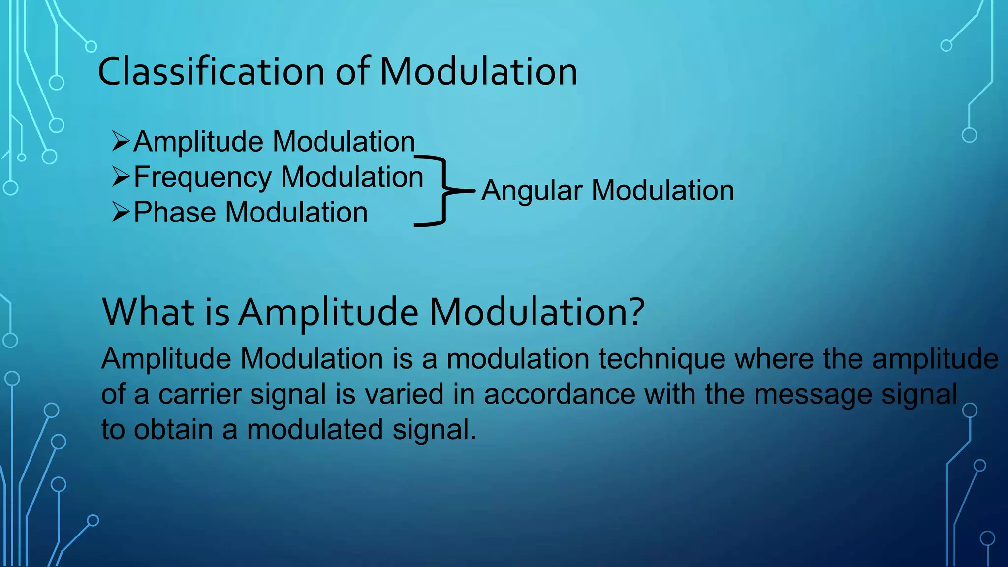
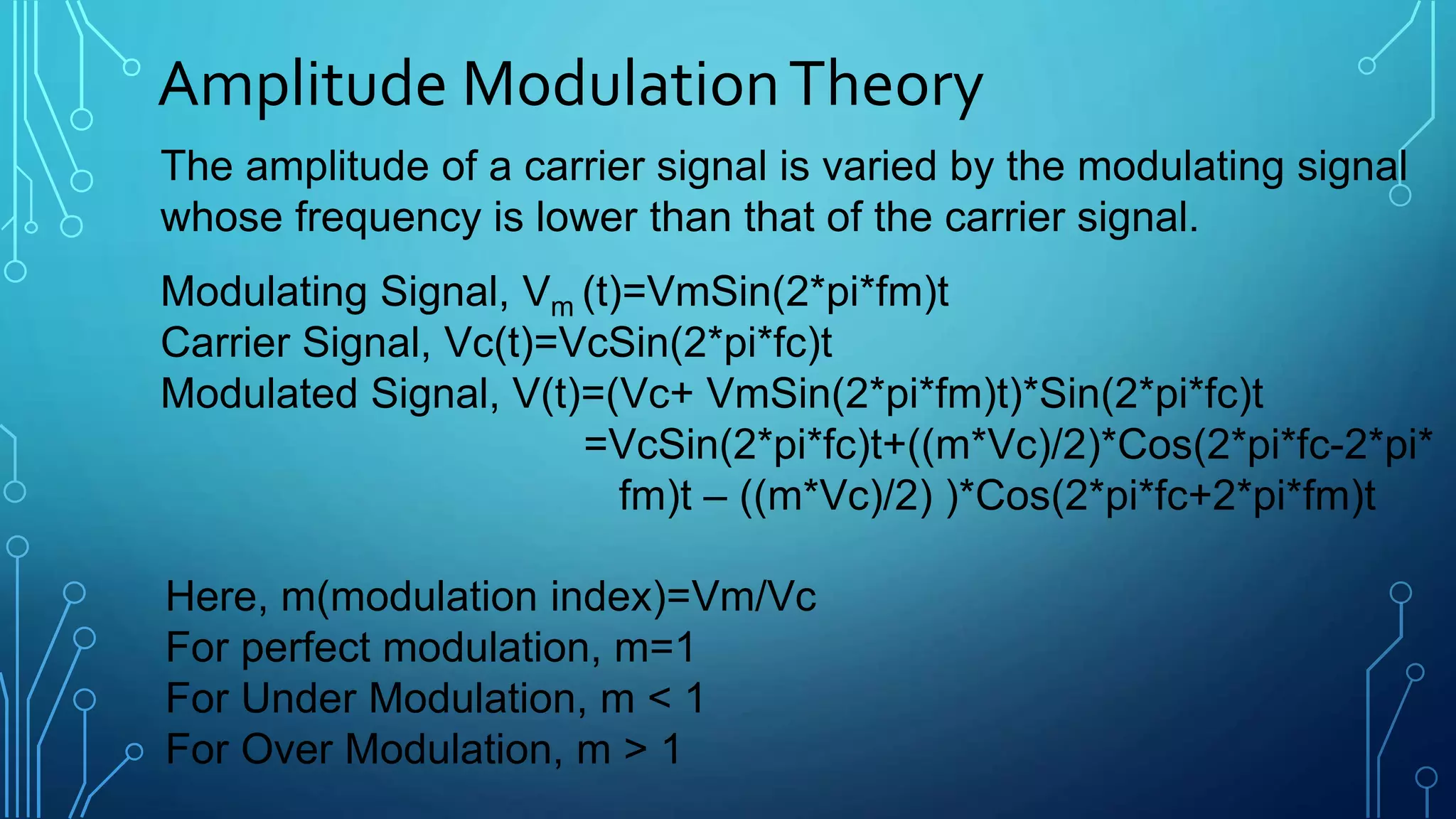
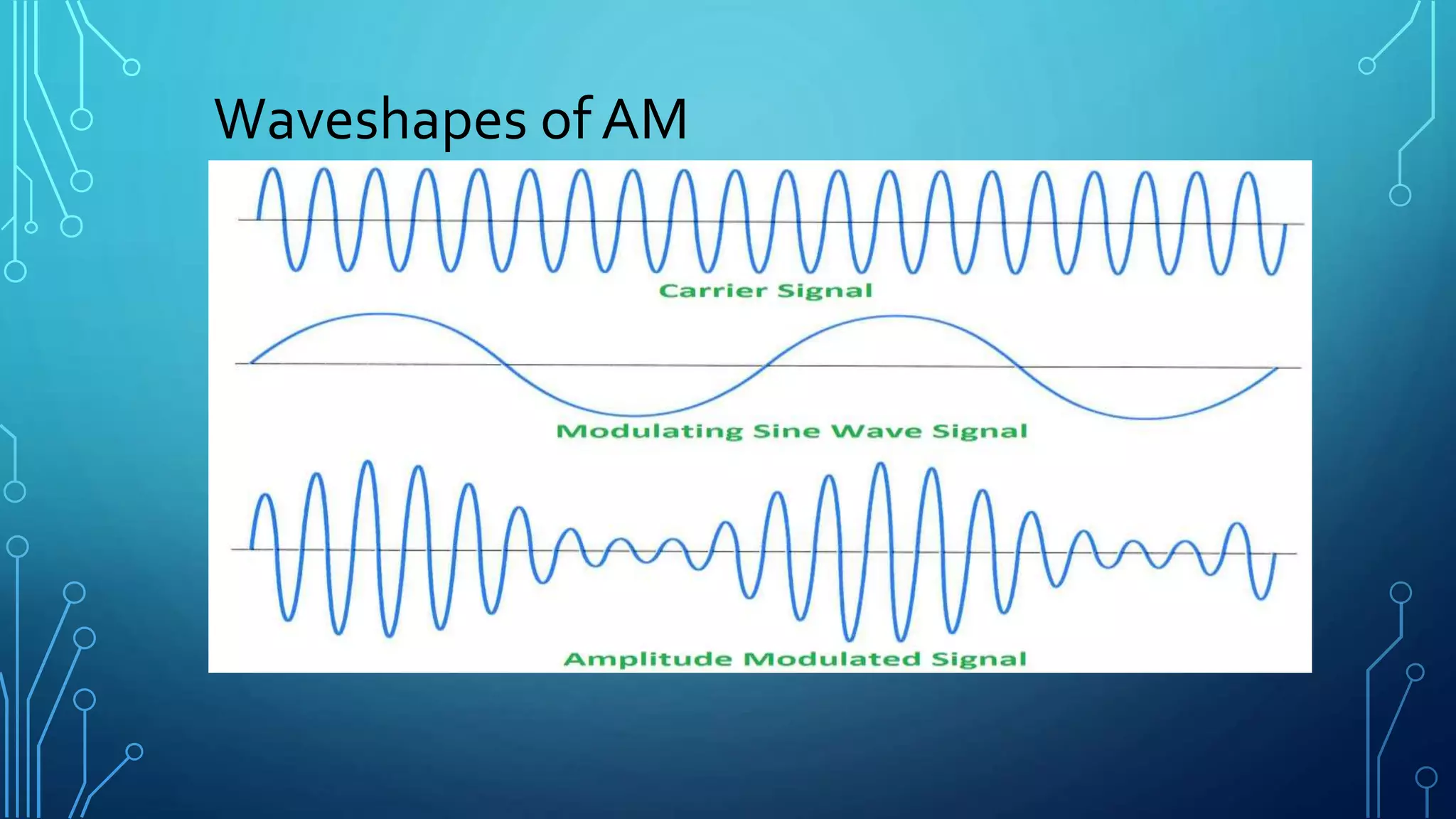
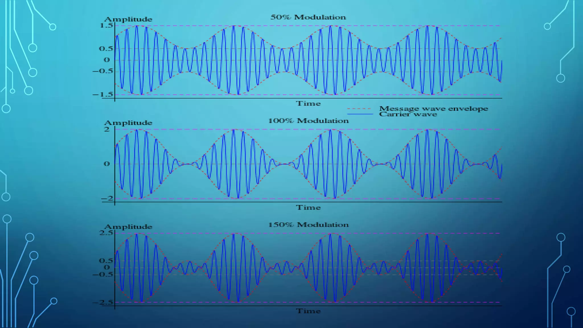
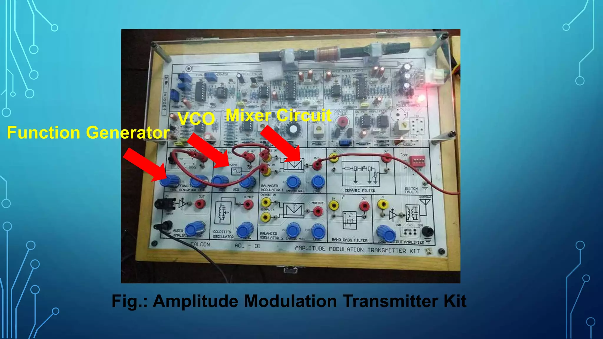
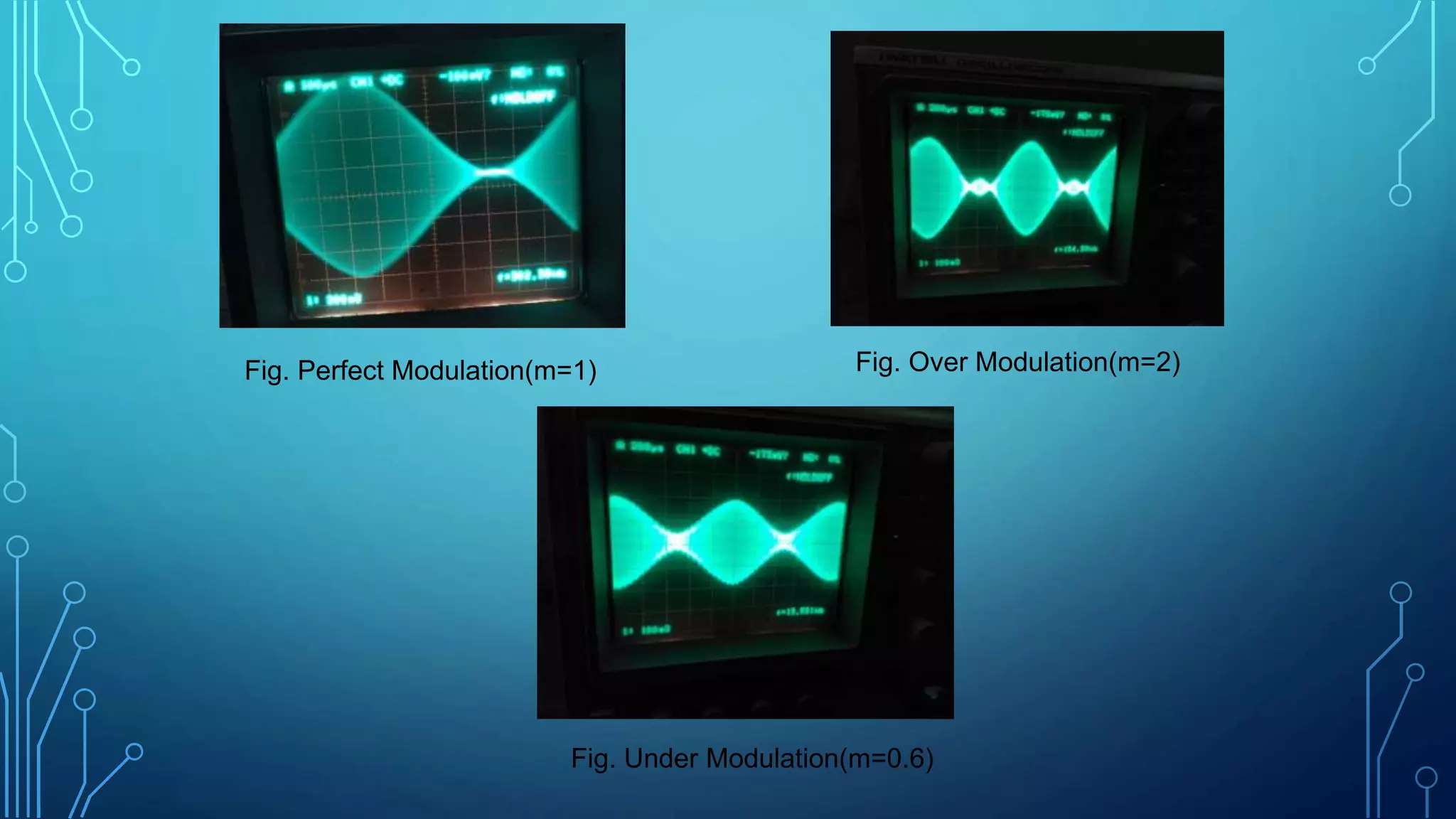
AMPLITUDE MODULATION
COURSE NO.: EEE 3218
COURSE TITLE: COMMUNICATION ENGINEERING II
SESSIONAL
Content
 What is Modulation?
 Why is Modulation needed?
 Classification of Modulation
 What is Amplitude Modulation?
 Amplitude Modulation Theory
 Waveshapes of AM
 Generation of AM in Laboratory
 List of Components
 Amplitude Demodulation Kits & Outputs
 Advantages & Disadvantages
 Applications
What is Modulation?
Modulation is the process by which the characteristics of a
carrier signal is varied according to the message signal.
Why is Modulation Needed?
 Message signal is incompatible for direct transmission. So its
strength has to be increased by modulation with a high frequency
carrier signal which doesn’t affect the parameters of message
signal.
Classification of Modulation
Amplitude Modulation
Frequency Modulation
Phase Modulation
What is Amplitude Modulation?
Amplitude Modulation is a modulation technique where the amplitude
of a carrier signal is varied in accordance with the message signal
to obtain a modulated signal.
Angular Modulation
Amplitude ModulationTheory
The amplitude of a carrier signal is varied by the modulating signal
whose frequency is lower than that of the carrier signal.
Modulating Signal, Vm (t)=VmSin(2*pi*fm)t
Carrier Signal, Vc(t)=VcSin(2*pi*fc)t
Modulated Signal, V(t)=(Vc+ VmSin(2*pi*fm)t)*Sin(2*pi*fc)t
=VcSin(2*pi*fc)t+((m*Vc)/2)*Cos(2*pi*fc-2*pi*
fm)t – ((m*Vc)/2) )*Cos(2*pi*fc+2*pi*fm)t
Here, m(modulation index)=Vm/Vc
For perfect modulation, m=1
For Under Modulation, m < 1
For Over Modulation, m > 1
Waveshapes of AM
Generation of AM in Laboratory
A function generator was used to generate a modulating signal and a voltage
controlled oscillator (VCO) was used to generate a carrier signal. Then, using
a mixer circuit, a modulated signal was generated.
Varying the amplitude of modulating signal, there were three types of modulation.
They were:
 Perfect Modulation
 Under Modulation
 Over Modulation
In overmodulation, one kind of distortion was occurred.
List of Components
Function Generator
Voltage Controlled Oscillator(VCO)
Mixer Circuit
Wires
Oscilloscope
Mixer CircuitVCO
Function Generator
Fig.: Amplitude Modulation Transmitter Kit
Fig. Perfect Modulation(m=1) Fig. Over Modulation(m=2)
Fig. Under Modulation(m=0.6)
Advantages
AM transmitters are less complex.
AM receivers are cost-effective.
Disadvantages
Not efficient in terms of power usage.
Not efficient in terms of bandwidth.
Application of AM
Broadcasting of both audio and
video signals.
Mobile, radio communications.
Aircraft communications.
Thank You

Amplitude modulation

  • 1.
    AMPLITUDE MODULATION COURSE NO.:EEE 3218 COURSE TITLE: COMMUNICATION ENGINEERING II SESSIONAL
  • 2.
    Content  What isModulation?  Why is Modulation needed?  Classification of Modulation  What is Amplitude Modulation?  Amplitude Modulation Theory  Waveshapes of AM  Generation of AM in Laboratory  List of Components  Amplitude Demodulation Kits & Outputs  Advantages & Disadvantages  Applications
  • 3.
    What is Modulation? Modulationis the process by which the characteristics of a carrier signal is varied according to the message signal. Why is Modulation Needed?  Message signal is incompatible for direct transmission. So its strength has to be increased by modulation with a high frequency carrier signal which doesn’t affect the parameters of message signal.
  • 4.
    Classification of Modulation AmplitudeModulation Frequency Modulation Phase Modulation What is Amplitude Modulation? Amplitude Modulation is a modulation technique where the amplitude of a carrier signal is varied in accordance with the message signal to obtain a modulated signal. Angular Modulation
  • 5.
    Amplitude ModulationTheory The amplitudeof a carrier signal is varied by the modulating signal whose frequency is lower than that of the carrier signal. Modulating Signal, Vm (t)=VmSin(2*pi*fm)t Carrier Signal, Vc(t)=VcSin(2*pi*fc)t Modulated Signal, V(t)=(Vc+ VmSin(2*pi*fm)t)*Sin(2*pi*fc)t =VcSin(2*pi*fc)t+((m*Vc)/2)*Cos(2*pi*fc-2*pi* fm)t – ((m*Vc)/2) )*Cos(2*pi*fc+2*pi*fm)t Here, m(modulation index)=Vm/Vc For perfect modulation, m=1 For Under Modulation, m < 1 For Over Modulation, m > 1
  • 6.
  • 8.
    Generation of AMin Laboratory A function generator was used to generate a modulating signal and a voltage controlled oscillator (VCO) was used to generate a carrier signal. Then, using a mixer circuit, a modulated signal was generated. Varying the amplitude of modulating signal, there were three types of modulation. They were:  Perfect Modulation  Under Modulation  Over Modulation In overmodulation, one kind of distortion was occurred.
  • 9.
    List of Components FunctionGenerator Voltage Controlled Oscillator(VCO) Mixer Circuit Wires Oscilloscope
  • 10.
    Mixer CircuitVCO Function Generator Fig.:Amplitude Modulation Transmitter Kit
  • 11.
    Fig. Perfect Modulation(m=1)Fig. Over Modulation(m=2) Fig. Under Modulation(m=0.6)
  • 12.
    Advantages AM transmitters areless complex. AM receivers are cost-effective. Disadvantages Not efficient in terms of power usage. Not efficient in terms of bandwidth.
  • 13.
    Application of AM Broadcastingof both audio and video signals. Mobile, radio communications. Aircraft communications.
  • 14.