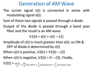
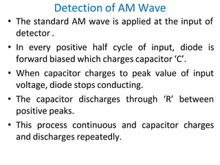
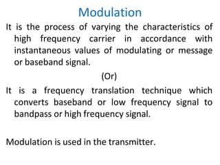
1) Modulation is the process of varying the characteristics of a high-frequency carrier signal in accordance with the message or baseband signal. This allows low-frequency signals to be transmitted over long distances.
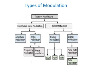
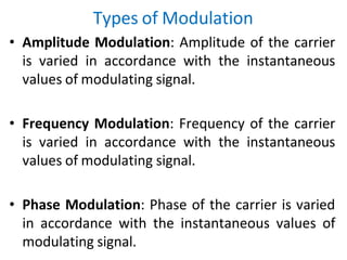
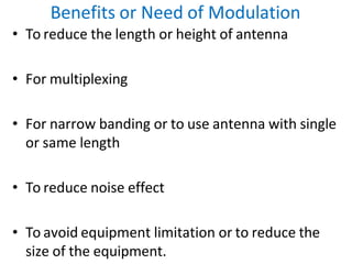
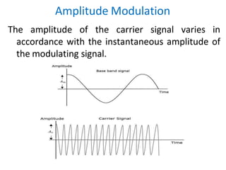
2) There are three main types of modulation: amplitude modulation, frequency modulation, and phase modulation. Amplitude modulation varies the amplitude of the carrier signal, frequency modulation varies the frequency, and phase modulation varies the phase.
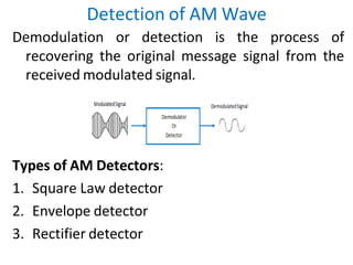
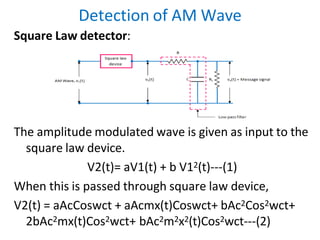
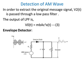
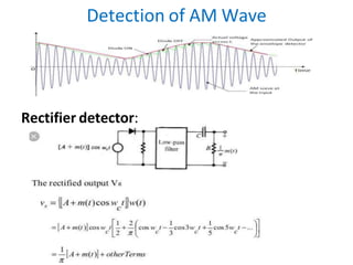
3) Demodulation or detection is the process of recovering the original message signal from the received modulated signal. Common detection methods for amplitude modulation include square law detection, envelope detection, and rectification.
![Amplitude Modulation
The standard equation for amplitude modulated
signal is expressed as,
S(t)= Ac Cos2πfct[1+ma(Cos2πfmt)]
Where, ma = Am/Ac = Modulation Index
Time Domain representation of AM:
S(t)=AcCos2πfct+μAc/2Cos[2πfc+2πfm]t+μAc/2Cos[2πfc-2πfm]t
I term: Carrier signal with amplitude Ac and frequency fc.
II.term: Amplitude= μAc/2, frequency= fc+fm , Upper sideband
frequency
III.term: Amplitude= μAc/2, frequency= fc-fm , Lower sideband
frequency](https://image.slidesharecdn.com/2-240313083333-72fec380/85/modulation-of-analog-communication-system-8-320.jpg)
![Amplitude Modulation
Frequency Domain representation of AM:
The time domain representation of AM wave is
given by,
S(t)= Ac Cos2πfct[1+ma(Cos2πfmt)]
Taking Fourier transform on both sides,
S(f) = Ac/2[δ(f-fc)+ δ(f+fc)] + Acma/2[M(f-fc)+ M(f+fc)]](https://image.slidesharecdn.com/2-240313083333-72fec380/85/modulation-of-analog-communication-system-9-320.jpg)
![Modulation Index
Modulation index or depth of modulation is given
by,
ma = [Amax-Amin/ Amax+Amin]= Am/Ac
Percentage of modulation index is,
%ma = [Amax-Amin/ Amax+Amin]X100= [Am/Ac ]X100
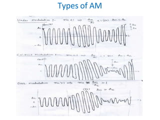
Types of AM with respect to modulation index:
• Under Modulation (ma <1)
• Critical Modulation (ma =1)
• Over Modulation (ma >1)](https://image.slidesharecdn.com/2-240313083333-72fec380/85/modulation-of-analog-communication-system-10-320.jpg)