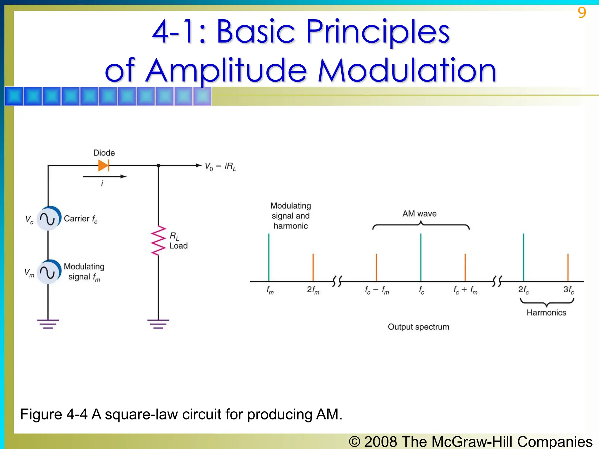
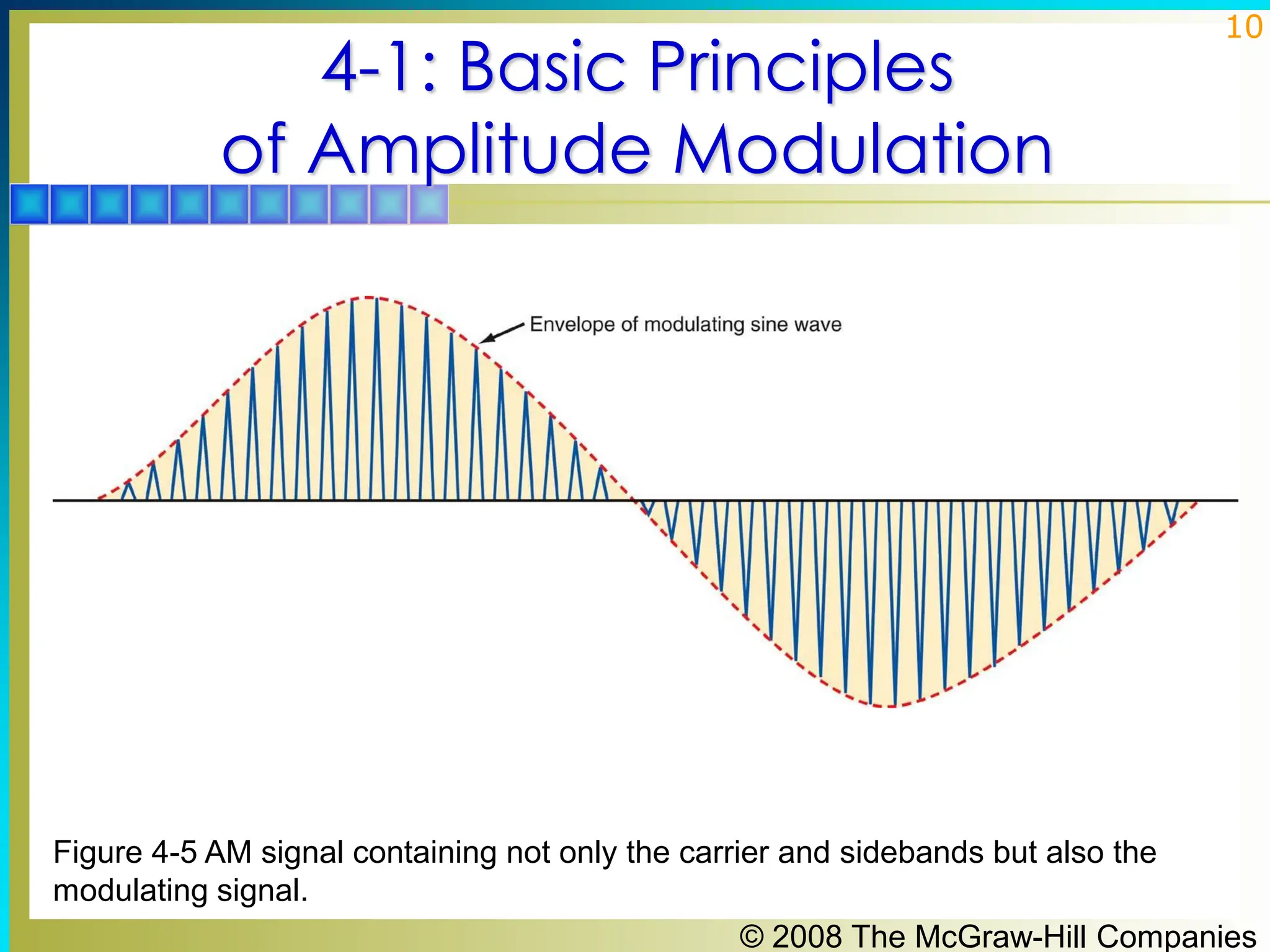
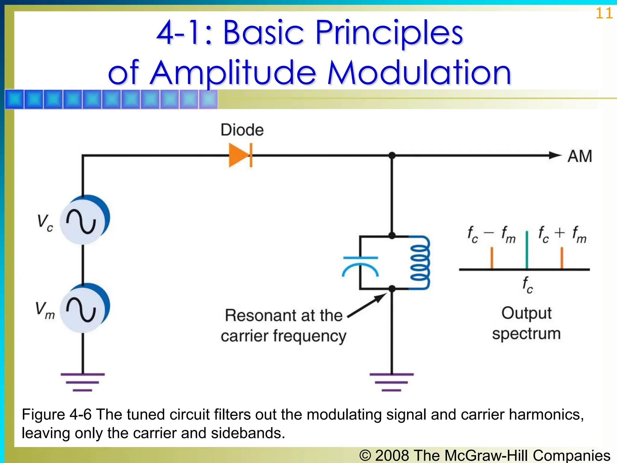
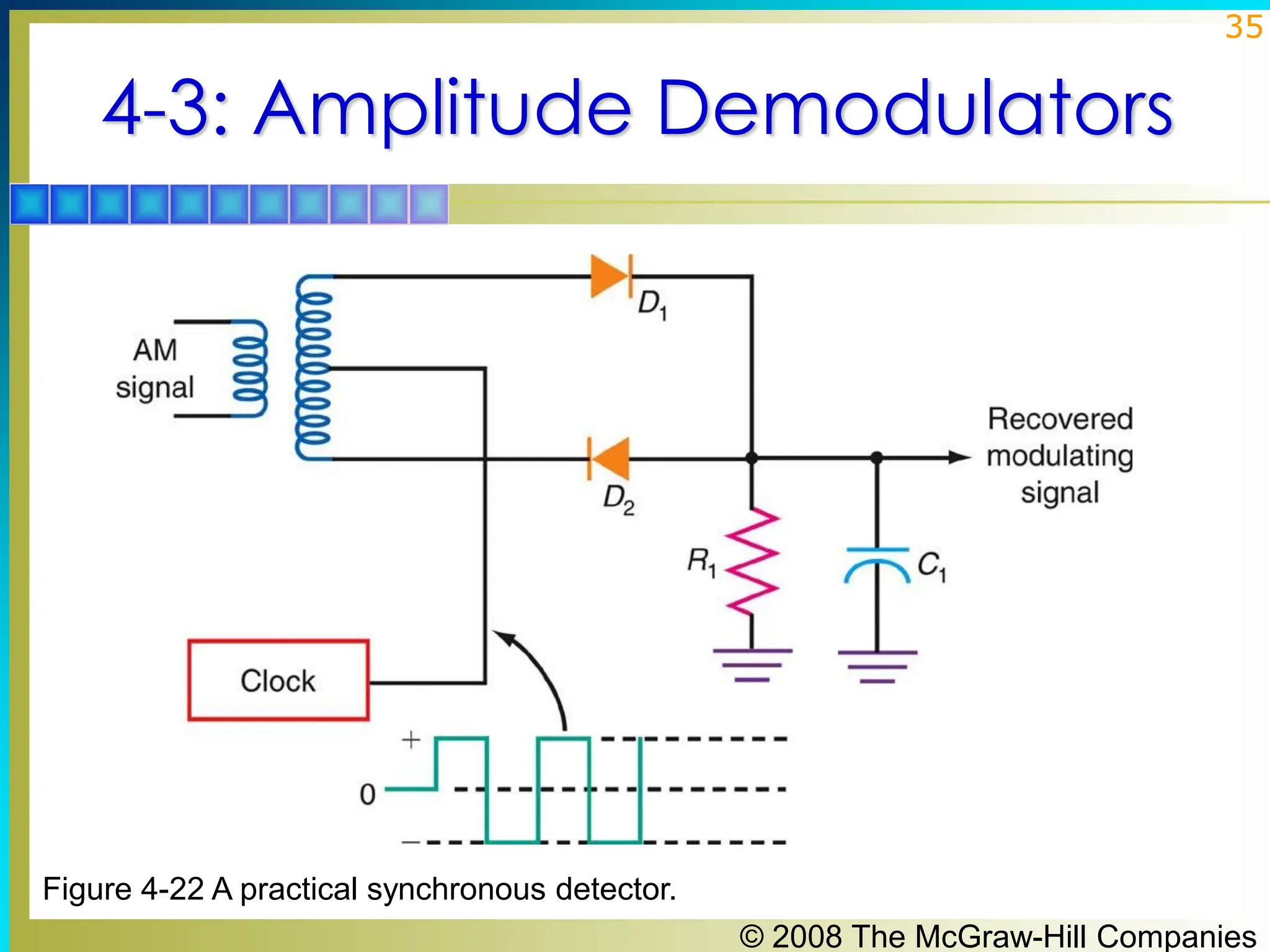
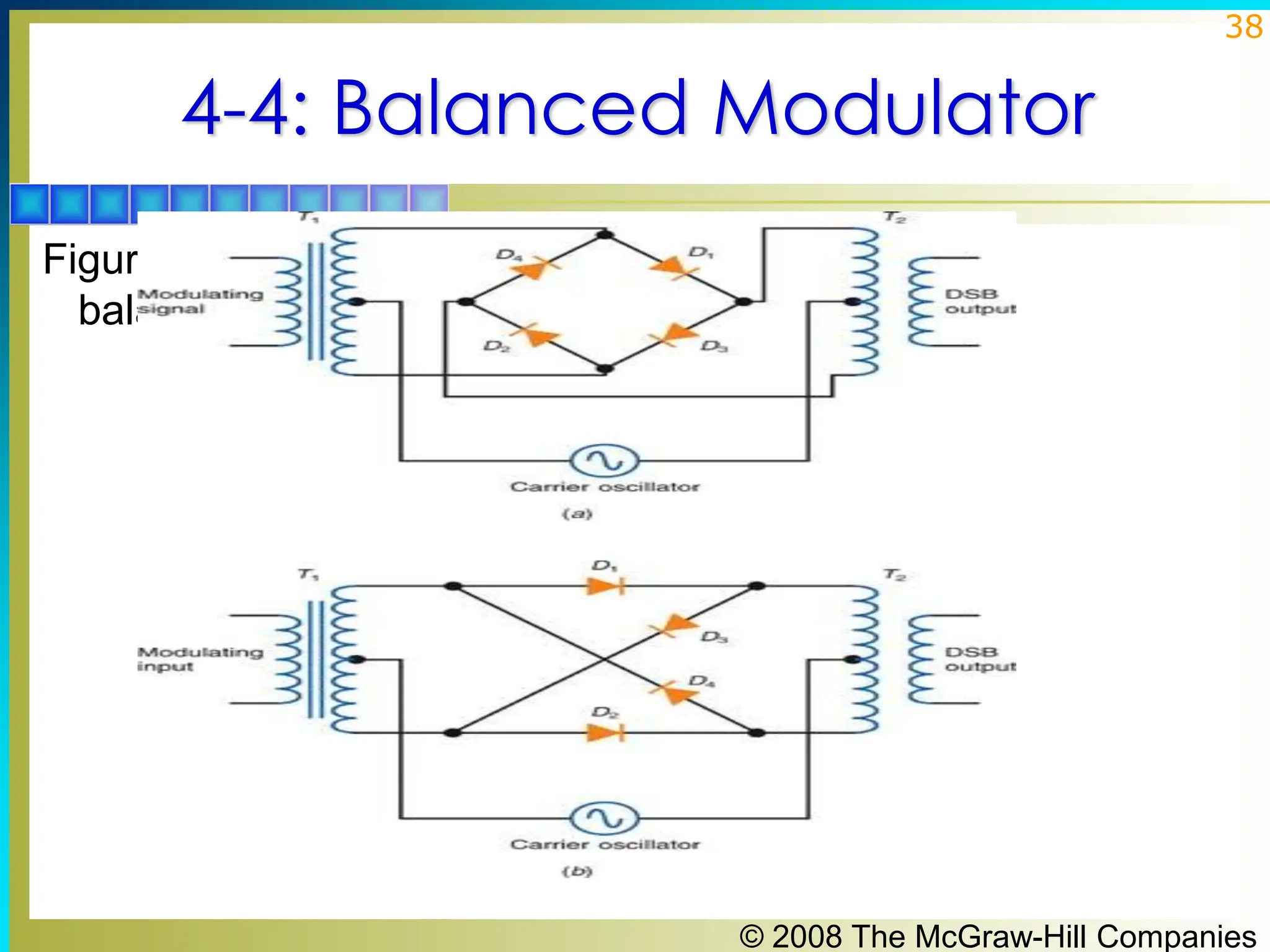
SlideShare a Scribd company logo
1 of 49
Download to read offline
1
Principles of Electronic
Communication Systems
Third Edition
Louis E. Frenzel, Jr.
© 2008 The McGraw-Hill Companies
2
Chapter 4
Amplitude Modulator
and Demodulator Circuits
© 2008 The McGraw-Hill Companies
3
Topics Covered in Chapter 4
▪ 4-1: Basic Principles of Amplitude Modulation
▪ 4-2: Amplitude Modulators
▪ 4-3: Amplitude Demodulators
▪ 4-4: Balanced Modulators
▪ 4-5: SSB Circuits
© 2008 The McGraw-Hill Companies
4
4-1: Basic Principles
of Amplitude Modulation
▪ Modulator circuits cause carrier amplitude to be varied
in accordance with modulating signals. Circuits
produce AM, DSB, and SSB transmission methods.
▪ The basic equation for an AM signal is
νAM = Vcsin 2πfct + (Vmsin 2πfmt)(sin 2πfct)
▪ The first term is the sine wave carrier
▪ The second term is the product of the sine wave
carrier and modulating signals.
© 2008 The McGraw-Hill Companies
5
4-1: Basic Principles
of Amplitude Modulation
AM in the Time Domain
▪ Amplitude modulation voltage is produced by a circuit
that can multiply the carrier by the modulating signal
and then add the carrier.
▪ If a circuit’s gain is a function of 1+ m sin 2πfmt, the
expression for the AM signal is
νAM = A(νc)
Where A is the gain or attenuation factor.
© 2008 The McGraw-Hill Companies
6
4-1: Basic Principles
of Amplitude Modulation
Figure 4-1 Block diagram of a circuit to produce AM.
© 2008 The McGraw-Hill Companies
7
4-1: Basic Principles
of Amplitude Modulation
AM in the Frequency Domain
▪ The product of the carrier and modulating signal can be
generated by applying both signals to a nonlinear
component such as a diode.
▪ A square-law function is one that varies in proportion
to the square of the input signals. A diode gives a good
approximation of a square-law response. Bipolar and
field-effect transistors (FETs) can also be biased to give
a square-law response.
© 2008 The McGraw-Hill Companies
8
4-1: Basic Principles
of Amplitude Modulation
AM in the Frequency Domain
▪ Diodes and transistors whose function is not a pure
square-law function produce third-, fourth-, and higher-
order harmonics, which are sometimes referred to as
intermodulation products.
▪ Intermodulation products are easy to filter out.
▪ Tuned circuits filter out the modulating signal and carrier
harmonics, leaving only carrier and sidebands.
© 2008 The McGraw-Hill Companies
9
4-1: Basic Principles
of Amplitude Modulation
Figure 4-4 A square-law circuit for producing AM.
© 2008 The McGraw-Hill Companies
10
4-1: Basic Principles
of Amplitude Modulation
Figure 4-5 AM signal containing not only the carrier and sidebands but also the
modulating signal.
© 2008 The McGraw-Hill Companies
11
4-1: Basic Principles
of Amplitude Modulation
Figure 4-6 The tuned circuit filters out the modulating signal and carrier harmonics,
leaving only the carrier and sidebands.
© 2008 The McGraw-Hill Companies
12
4-2: Amplitude Modulators
▪ There are two types of amplitude modulators. They
are low-level and high-level modulators.
▪ Low-level modulators generate AM with small signals
and must be amplified before transmission.
▪ High-level modulators produce AM at high power
levels, usually in the final amplifier stage of a
transmitter.
© 2008 The McGraw-Hill Companies
13
4-2: Amplitude Modulators
Low-Level AM: Diode Modulator
▪ Diode modulation consists of a resistive mixing
network, a diode rectifier, and an LC tuned circuit.
▪ A diode passes half cycles when forward biased.
▪ The coil and capacitor repeatedly exchange energy,
causing an oscillation or ringing at the resonant
frequency.
© 2008 The McGraw-Hill Companies
14
4-2: Amplitude Modulators
Figure 4-7 Amplitude modulation with a diode.
© 2008 The McGraw-Hill Companies
15
4-2: Amplitude Modulators
Low-Level AM: Transistor Modulator
▪ Transistor modulation consists of a resistive mixing
network, a transistor, and an LC tuned circuit.
▪ The emitter-base junction of the transistor serves as a
diode and nonlinear device.
▪ Modulation and amplification occur as base current
controls a larger collector current.
▪ The LC tuned circuit oscillates (rings) to generate the
missing half cycle.
© 2008 The McGraw-Hill Companies
16
4-2: Amplitude Modulators
Figure 4-9 Simple transistor modulator.
© 2008 The McGraw-Hill Companies
17
4-2: Amplitude Modulators
Low-Level AM: PIN Diode Modulator
▪ Variable attenuator circuits using PIN diodes produce
AM at VHF, UHF, and microwave frequencies.
▪ When PIN diodes are forward-biased, they operate as
variable resistors.
▪ Attenuation caused by PIN diode circuits varies with the
amplitude of the modulating signal.
© 2008 The McGraw-Hill Companies
18
4-2: Amplitude Modulators
Figure 4-10 High-frequency amplitude modulators using PIN diodes.
© 2008 The McGraw-Hill Companies
19
4-2: Amplitude Modulators
Low-Level AM: Differential Amplifier
▪ Differential amplifier modulators make excellent
amplitude modulators because they have a high gain,
good linearity and can be 100 percent modulated.
▪ The output voltage can be taken between two
collectors, producing a balanced, or differential,
output.
▪ The output can also be taken from the output of either
collector to ground, producing a single-ended output.
© 2008 The McGraw-Hill Companies
20
4-2: Amplitude Modulators
Figure 4-11 (a) Basic differential amplifier. (b) Differential amplifier modulator.
© 2008 The McGraw-Hill Companies
21
4-2: Amplitude Modulators
Figure 4-11 (a) Basic differential amplifier. (b) Differential amplifier modulator.
© 2008 The McGraw-Hill Companies
22
4-2: Amplitude Modulators
Figure 4-11 (a) Basic differential amplifier. (b) Differential amplifier modulator.
© 2008 The McGraw-Hill Companies
23
4-2: Amplitude Modulators
High-Level AM
▪ In high-level modulation, the modulator varies the
voltage and power in the final RF amplifier stage of the
transmitter.
▪ The result is high efficiency in the RF amplifier and
overall high-quality performance.
© 2008 The McGraw-Hill Companies
24
4-2: Amplitude Modulators
High-Level AM: Collector Modulator
▪ The collector modulator is a linear power amplifier
that takes the low-level modulating signals and
amplifies them to a high-power level.
▪ A modulating output signal is coupled through a
modulation transformer to a class C amplifier.
▪ The secondary winding of the modulation transformer is
connected in series with the collector supply voltage of
the class C amplifier.
© 2008 The McGraw-Hill Companies
25
4-2: Amplitude Modulators
Figure 4-13 A high-level collector modulator.
© 2008 The McGraw-Hill Companies
26
4-2: Amplitude Modulators
High-Level AM: Series Modulator
▪ A series modulator produces high-level modulation
without a large and expensive modulation transformer
used in collector modulators.
▪ It improves frequency response.
▪ It is, however, very inefficient.
© 2008 The McGraw-Hill Companies
27
4-2: Amplitude Modulators
High-Level AM: Series Modulator
▪ A series modulator replaces the modulation
transformer with an emitter follower.
▪ The modulating signal is applied to the emitter
follower.
▪ The emitter follower is in series with the collector
supply voltage.
▪ The collector voltage changes with variations in the
amplified audio modulating signal.
© 2008 The McGraw-Hill Companies
28
4-2: Amplitude Modulators
Figure 4-15 Series modulation. Transistors may also be MOSFETs with appropriate
biasing.
© 2008 The McGraw-Hill Companies
29
4-3: Amplitude Demodulators
▪ Demodulators, or detectors, are circuits that accept
modulated signals and recover the original modulating
information.
© 2008 The McGraw-Hill Companies
30
4-3: Amplitude Demodulators
Figure 4-16 A diode detector AM demodulator.
© 2008 The McGraw-Hill Companies
31
4-3: Amplitude Demodulators
Diode Detector
▪ On positive alternations of the AM signal, the
capacitor charges quickly to the peak value of pulses
passed by the diode.
▪ When the pulse voltage drops to zero, the capacitor
discharges into the resistor.
▪ The time constant of the capacitor and resistor is long
compared to the period of the carrier.
▪ The capacitor discharges only slightly when the diode
is not conducting.
▪ The resulting waveform across the capacitor is a
close approximation to the original modulating signal.
© 2008 The McGraw-Hill Companies
32
4-3: Amplitude Demodulators
Diode Detector
▪ Because the diode detector recovers the envelope of
the AM (modulating) signal, the circuit is sometimes
called an envelope detector.
▪ If the RC time constant in a diode detector is too long,
the capacitor discharge will be too slow to follow the
faster changes in the modulating signal.
▪ This is referred to as diagonal distortion.
© 2008 The McGraw-Hill Companies
33
4-3: Amplitude Demodulators
Synchronous Detection
▪ Synchronous detectors use an internal clock signal at
the carrier frequency in the receiver to switch the AM
signal off and on, producing rectification similar to that
in a standard diode detector.
▪ Synchronous detectors or coherent detectors have
less distortion and a better signal-to-noise ratio than
standard diode detectors.
© 2008 The McGraw-Hill Companies
34
4-3: Amplitude Demodulators
Synchronous Detection
▪ The key to making the synchronous detector work is to
ensure that the signal producing the switching action is
perfectly in phase with the received AM carrier.
▪ An internally generated carrier signal from an oscillator
will not work.
© 2008 The McGraw-Hill Companies
35
4-3: Amplitude Demodulators
Figure 4-22 A practical synchronous detector.
© 2008 The McGraw-Hill Companies
36
4-4: Balanced Modulator
▪ A balanced modulator is a circuit that generates a
DSB signal, suppressing the carrier and leaving only
the sum and difference frequencies at the output.
▪ The output of a balanced modulator can be further
processed by filters or phase-shifting circuitry to
eliminate one of the sidebands, resulting in a SSB
signal.
▪ Types of balanced modulators include lattice,
1496/1596 IC, and the analog multiplier.
© 2008 The McGraw-Hill Companies
37
4-4: Balanced Modulator
Lattice Modulator
▪ A popular and widely used balanced modulator is the
diode ring or lattice modulator.
▪ The lattice modulator consists of an input transformer,
an output transformer and four diodes connected in a
bridge circuit.
▪ The carrier signal is applied to the center taps of the
input and output transformers.
▪ The modulating signal is applied to the input
transformer.
▪ The output appears across the output transformer.
© 2008 The McGraw-Hill Companies
38
4-4: Balanced Modulator
Figure 4-24: Lattice-type
balanced modulator.
© 2008 The McGraw-Hill Companies
39
4-4: Balanced Modulator
Lattice Modulators
▪ The carrier sine wave is considerably higher in
frequency and amplitude than the modulating signal.
▪ The carrier sine wave is used as a source of forward
and reverse bias for the diodes.
▪ The carrier turns the diodes off and on at a high rate of
speed.
▪ The diodes act like switches that connect the
modulating signal at the secondary of T1 to the primary
of T2.
© 2008 The McGraw-Hill Companies
40
4-4: Balanced Modulator
IC Balanced Modulators
▪ The 1496/1596 IC is a versatile circuit available for
communication applications.
▪ It can work at carrier frequencies up to 100 MHz.
▪ It can achieve a carrier suppression of 50 to 65 dB.
▪ The 1496/1596 IC can operate as a balanced modulator
or configured to perform as an amplitude modulator, a
product detector, or a synchronous detector.
© 2008 The McGraw-Hill Companies
41
4-4: Balanced Modulator
IC Balanced Modulators: Analog Multiplier
▪ An analog multiplier is a type of integrated circuit that
can be used as a balanced modulator.
▪ Analog multipliers are often used to generate DSB
signals.
▪ The analog multiplier is not a switching circuit like the
balanced modulator.
▪ The analog multiplier uses differential amplifiers
operating in the linear mode.
▪ The carrier must be a sine wave and the multiplier
produces the true product of two analog inputs.
© 2008 The McGraw-Hill Companies
42
4-5: SSB Circuits
Generating SSB Signals: The Filter Method
▪ The filter method is the simplest and most widely used
method of generating SSB signals.
▪ The modulating signal is applied to the audio amplifier.
▪ The amplifier’s output is fed to one input of a balanced
modulator.
▪ A crystal oscillator provides the carrier signal which is
also applied to the balanced modulator.
© 2008 The McGraw-Hill Companies
43
4-5: SSB Circuits
Generating SSB Signals: The Filter Method
▪ The output of the balanced modulator is a double-
sideband (DSB) signal.
▪ An SSB signal is produced by passing the DSB signal
through a highly selective bandpass filter.
▪ With the filter method, it is necessary to select either the
upper or the lower sideband.
© 2008 The McGraw-Hill Companies
44
4-5: SSB Circuits
Figure 4-31 An SSB transmitter using the filter method.
© 2008 The McGraw-Hill Companies
45
4-5: SSB Circuits
Generating SSB Signals: Phasing Method
▪ The phasing method of SSB generation uses a
phase-shift technique that causes one of the
sidebands to be canceled out.
▪ The phasing method uses two balanced modulators
which eliminate the carrier.
▪ The carrier oscillator is applied to the upper balanced
modulator along with the modulating signal.
© 2008 The McGraw-Hill Companies
46
4-5: SSB Circuits
Generating SSB Signals: Phasing Method
▪ The carrier and modulating signals are both shifted in
phase by 90 degrees and applied to another balanced
modulator.
▪ Phase-shifting causes one sideband to be canceled out
when the two modulator outputs are added together.
© 2008 The McGraw-Hill Companies
47
4-5: SSB Circuits
Figure 4-33 An SSB generator using the phasing method.
© 2008 The McGraw-Hill Companies
48
4-5: SSB Circuits
DSB and SSB Demodulation
▪ To recover the intelligence in a DSB or SSB signal, the
carrier that was suppressed at the receiver must be
reinserted.
▪ A product detector is a balanced modulator used in a
receiver to recover the modulating signal.
▪ Any balanced modulator can be used as a product
detector to demodulate SSB signals.
© 2008 The McGraw-Hill Companies
49
4-5: SSB Circuits
Figure 4-38 A balanced modulator used as a product detector to demodulate an SSB
signal.

More Related Content

Similar to WEEK-10-AM-MODULATOR-DEMODULATOR.pdf

Similar to WEEK-10-AM-MODULATOR-DEMODULATOR.pdf (20)

Carrier and chopper amplifiers
Carrier and chopper amplifiers Carrier and chopper amplifiers
Carrier and chopper amplifiers
 
Special transformers
Special transformersSpecial transformers
Special transformers
 
Automatic doorbell with object detection
Automatic doorbell with object detectionAutomatic doorbell with object detection
Automatic doorbell with object detection
 
Microwave Coupler
Microwave CouplerMicrowave Coupler
Microwave Coupler
 
waveguide-1
waveguide-1waveguide-1
waveguide-1
 
ALBA MANUFACTURING OF TRANSFORMERS.pptx
ALBA MANUFACTURING OF TRANSFORMERS.pptxALBA MANUFACTURING OF TRANSFORMERS.pptx
ALBA MANUFACTURING OF TRANSFORMERS.pptx
 
Transmit / Receive (T/R) Modules for Radar Systems
Transmit / Receive (T/R) Modules for Radar SystemsTransmit / Receive (T/R) Modules for Radar Systems
Transmit / Receive (T/R) Modules for Radar Systems
 
Ppt iitr
Ppt iitrPpt iitr
Ppt iitr
 
Electronic circuits ii
Electronic circuits iiElectronic circuits ii
Electronic circuits ii
 
Traffic wireless(eee499.blogspot.com)
Traffic wireless(eee499.blogspot.com)Traffic wireless(eee499.blogspot.com)
Traffic wireless(eee499.blogspot.com)
 
Amplitude modulation & demodulation
Amplitude modulation & demodulation Amplitude modulation & demodulation
Amplitude modulation & demodulation
 
Fundamental of FM modulation and demodulation.ppt
Fundamental of FM modulation and demodulation.pptFundamental of FM modulation and demodulation.ppt
Fundamental of FM modulation and demodulation.ppt
 
Design_of_Power_Transformers.ppt
Design_of_Power_Transformers.pptDesign_of_Power_Transformers.ppt
Design_of_Power_Transformers.ppt
 
Amplifiers.pdf
Amplifiers.pdfAmplifiers.pdf
Amplifiers.pdf
 
“Microcontroller Based Substation Monitoring system with gsm modem”.
“Microcontroller Based Substation Monitoring system with gsm modem”.“Microcontroller Based Substation Monitoring system with gsm modem”.
“Microcontroller Based Substation Monitoring system with gsm modem”.
 
Transformer
TransformerTransformer
Transformer
 
The AM Receiver and Audio Amplification Project
The AM Receiver and Audio Amplification ProjectThe AM Receiver and Audio Amplification Project
The AM Receiver and Audio Amplification Project
 
Ch14 transmission line. Class 11 cbse ..
Ch14 transmission line. Class 11 cbse ..Ch14 transmission line. Class 11 cbse ..
Ch14 transmission line. Class 11 cbse ..
 
Am fm transmitter
Am fm transmitterAm fm transmitter
Am fm transmitter
 
lecture_11.pptx
lecture_11.pptxlecture_11.pptx
lecture_11.pptx
 

Recently uploaded

Call Now ≽ 9953056974 ≼🔝 Call Girls In New Ashok Nagar ≼🔝 Delhi door step de...
Call Now ≽ 9953056974 ≼🔝 Call Girls In New Ashok Nagar  ≼🔝 Delhi door step de...Call Now ≽ 9953056974 ≼🔝 Call Girls In New Ashok Nagar  ≼🔝 Delhi door step de...
Call Now ≽ 9953056974 ≼🔝 Call Girls In New Ashok Nagar ≼🔝 Delhi door step de...
9953056974 Low Rate Call Girls In Saket, Delhi NCR
 
XXXXXXXXXXXXXXXXXXXXXXXXXXXXXXXXXXXXXXXXXXXXXXXXXXXX
XXXXXXXXXXXXXXXXXXXXXXXXXXXXXXXXXXXXXXXXXXXXXXXXXXXXXXXXXXXXXXXXXXXXXXXXXXXXXXXXXXXXXXXXXXXXXXXXXXXXXXXX
XXXXXXXXXXXXXXXXXXXXXXXXXXXXXXXXXXXXXXXXXXXXXXXXXXXX
ssuser89054b
 
Call Girls in Ramesh Nagar Delhi 💯 Call Us 🔝9953056974 🔝 Escort Service
Call Girls in Ramesh Nagar Delhi 💯 Call Us 🔝9953056974 🔝 Escort ServiceCall Girls in Ramesh Nagar Delhi 💯 Call Us 🔝9953056974 🔝 Escort Service
Call Girls in Ramesh Nagar Delhi 💯 Call Us 🔝9953056974 🔝 Escort Service
9953056974 Low Rate Call Girls In Saket, Delhi NCR
 
Call Girls in Netaji Nagar, Delhi 💯 Call Us 🔝9953056974 🔝 Escort Service
Call Girls in Netaji Nagar, Delhi 💯 Call Us 🔝9953056974 🔝 Escort ServiceCall Girls in Netaji Nagar, Delhi 💯 Call Us 🔝9953056974 🔝 Escort Service
Call Girls in Netaji Nagar, Delhi 💯 Call Us 🔝9953056974 🔝 Escort Service
9953056974 Low Rate Call Girls In Saket, Delhi NCR
 
Top Rated Call Girls In chittoor 📱 {7001035870} VIP Escorts chittoor
Top Rated Call Girls In chittoor 📱 {7001035870} VIP Escorts chittoorTop Rated Call Girls In chittoor 📱 {7001035870} VIP Escorts chittoor
Top Rated Call Girls In chittoor 📱 {7001035870} VIP Escorts chittoor
dharasingh5698
 

Recently uploaded (20)

FEA Based Level 3 Assessment of Deformed Tanks with Fluid Induced Loads
FEA Based Level 3 Assessment of Deformed Tanks with Fluid Induced LoadsFEA Based Level 3 Assessment of Deformed Tanks with Fluid Induced Loads
FEA Based Level 3 Assessment of Deformed Tanks with Fluid Induced Loads
 
Call Now ≽ 9953056974 ≼🔝 Call Girls In New Ashok Nagar ≼🔝 Delhi door step de...
Call Now ≽ 9953056974 ≼🔝 Call Girls In New Ashok Nagar  ≼🔝 Delhi door step de...Call Now ≽ 9953056974 ≼🔝 Call Girls In New Ashok Nagar  ≼🔝 Delhi door step de...
Call Now ≽ 9953056974 ≼🔝 Call Girls In New Ashok Nagar ≼🔝 Delhi door step de...
 
Block diagram reduction techniques in control systems.ppt
Block diagram reduction techniques in control systems.pptBlock diagram reduction techniques in control systems.ppt
Block diagram reduction techniques in control systems.ppt
 
XXXXXXXXXXXXXXXXXXXXXXXXXXXXXXXXXXXXXXXXXXXXXXXXXXXX
XXXXXXXXXXXXXXXXXXXXXXXXXXXXXXXXXXXXXXXXXXXXXXXXXXXXXXXXXXXXXXXXXXXXXXXXXXXXXXXXXXXXXXXXXXXXXXXXXXXXXXXX
XXXXXXXXXXXXXXXXXXXXXXXXXXXXXXXXXXXXXXXXXXXXXXXXXXXX
 
Hazard Identification (HAZID) vs. Hazard and Operability (HAZOP): A Comparati...
Hazard Identification (HAZID) vs. Hazard and Operability (HAZOP): A Comparati...Hazard Identification (HAZID) vs. Hazard and Operability (HAZOP): A Comparati...
Hazard Identification (HAZID) vs. Hazard and Operability (HAZOP): A Comparati...
 
Unleashing the Power of the SORA AI lastest leap
Unleashing the Power of the SORA AI lastest leapUnleashing the Power of the SORA AI lastest leap
Unleashing the Power of the SORA AI lastest leap
 
2016EF22_0 solar project report rooftop projects
2016EF22_0 solar project report rooftop projects2016EF22_0 solar project report rooftop projects
2016EF22_0 solar project report rooftop projects
 
Minimum and Maximum Modes of microprocessor 8086
Minimum and Maximum Modes of microprocessor 8086Minimum and Maximum Modes of microprocessor 8086
Minimum and Maximum Modes of microprocessor 8086
 
COST-EFFETIVE and Energy Efficient BUILDINGS ptx
COST-EFFETIVE  and Energy Efficient BUILDINGS ptxCOST-EFFETIVE  and Energy Efficient BUILDINGS ptx
COST-EFFETIVE and Energy Efficient BUILDINGS ptx
 
ONLINE FOOD ORDER SYSTEM PROJECT REPORT.pdf
ONLINE FOOD ORDER SYSTEM PROJECT REPORT.pdfONLINE FOOD ORDER SYSTEM PROJECT REPORT.pdf
ONLINE FOOD ORDER SYSTEM PROJECT REPORT.pdf
 
Call Girls Wakad Call Me 7737669865 Budget Friendly No Advance Booking
Call Girls Wakad Call Me 7737669865 Budget Friendly No Advance BookingCall Girls Wakad Call Me 7737669865 Budget Friendly No Advance Booking
Call Girls Wakad Call Me 7737669865 Budget Friendly No Advance Booking
 
Design For Accessibility: Getting it right from the start
Design For Accessibility: Getting it right from the startDesign For Accessibility: Getting it right from the start
Design For Accessibility: Getting it right from the start
 
Call Girls in Ramesh Nagar Delhi 💯 Call Us 🔝9953056974 🔝 Escort Service
Call Girls in Ramesh Nagar Delhi 💯 Call Us 🔝9953056974 🔝 Escort ServiceCall Girls in Ramesh Nagar Delhi 💯 Call Us 🔝9953056974 🔝 Escort Service
Call Girls in Ramesh Nagar Delhi 💯 Call Us 🔝9953056974 🔝 Escort Service
 
Water Industry Process Automation & Control Monthly - April 2024
Water Industry Process Automation & Control Monthly - April 2024Water Industry Process Automation & Control Monthly - April 2024
Water Industry Process Automation & Control Monthly - April 2024
 
data_management_and _data_science_cheat_sheet.pdf
data_management_and _data_science_cheat_sheet.pdfdata_management_and _data_science_cheat_sheet.pdf
data_management_and _data_science_cheat_sheet.pdf
 
Call Girls in Netaji Nagar, Delhi 💯 Call Us 🔝9953056974 🔝 Escort Service
Call Girls in Netaji Nagar, Delhi 💯 Call Us 🔝9953056974 🔝 Escort ServiceCall Girls in Netaji Nagar, Delhi 💯 Call Us 🔝9953056974 🔝 Escort Service
Call Girls in Netaji Nagar, Delhi 💯 Call Us 🔝9953056974 🔝 Escort Service
 
chapter 5.pptx: drainage and irrigation engineering
chapter 5.pptx: drainage and irrigation engineeringchapter 5.pptx: drainage and irrigation engineering
chapter 5.pptx: drainage and irrigation engineering
 
(INDIRA) Call Girl Bhosari Call Now 8617697112 Bhosari Escorts 24x7
(INDIRA) Call Girl Bhosari Call Now 8617697112 Bhosari Escorts 24x7(INDIRA) Call Girl Bhosari Call Now 8617697112 Bhosari Escorts 24x7
(INDIRA) Call Girl Bhosari Call Now 8617697112 Bhosari Escorts 24x7
 
A Study of Urban Area Plan for Pabna Municipality
A Study of Urban Area Plan for Pabna MunicipalityA Study of Urban Area Plan for Pabna Municipality
A Study of Urban Area Plan for Pabna Municipality
 
Top Rated Call Girls In chittoor 📱 {7001035870} VIP Escorts chittoor
Top Rated Call Girls In chittoor 📱 {7001035870} VIP Escorts chittoorTop Rated Call Girls In chittoor 📱 {7001035870} VIP Escorts chittoor
Top Rated Call Girls In chittoor 📱 {7001035870} VIP Escorts chittoor
 

WEEK-10-AM-MODULATOR-DEMODULATOR.pdf

  • 1. 1 Principles of Electronic Communication Systems Third Edition Louis E. Frenzel, Jr. © 2008 The McGraw-Hill Companies
  • 2. 2 Chapter 4 Amplitude Modulator and Demodulator Circuits
  • 3. © 2008 The McGraw-Hill Companies 3 Topics Covered in Chapter 4 ▪ 4-1: Basic Principles of Amplitude Modulation ▪ 4-2: Amplitude Modulators ▪ 4-3: Amplitude Demodulators ▪ 4-4: Balanced Modulators ▪ 4-5: SSB Circuits
  • 4. © 2008 The McGraw-Hill Companies 4 4-1: Basic Principles of Amplitude Modulation ▪ Modulator circuits cause carrier amplitude to be varied in accordance with modulating signals. Circuits produce AM, DSB, and SSB transmission methods. ▪ The basic equation for an AM signal is νAM = Vcsin 2πfct + (Vmsin 2πfmt)(sin 2πfct) ▪ The first term is the sine wave carrier ▪ The second term is the product of the sine wave carrier and modulating signals.
  • 5. © 2008 The McGraw-Hill Companies 5 4-1: Basic Principles of Amplitude Modulation AM in the Time Domain ▪ Amplitude modulation voltage is produced by a circuit that can multiply the carrier by the modulating signal and then add the carrier. ▪ If a circuit’s gain is a function of 1+ m sin 2πfmt, the expression for the AM signal is νAM = A(νc) Where A is the gain or attenuation factor.
  • 6. © 2008 The McGraw-Hill Companies 6 4-1: Basic Principles of Amplitude Modulation Figure 4-1 Block diagram of a circuit to produce AM.
  • 7. © 2008 The McGraw-Hill Companies 7 4-1: Basic Principles of Amplitude Modulation AM in the Frequency Domain ▪ The product of the carrier and modulating signal can be generated by applying both signals to a nonlinear component such as a diode. ▪ A square-law function is one that varies in proportion to the square of the input signals. A diode gives a good approximation of a square-law response. Bipolar and field-effect transistors (FETs) can also be biased to give a square-law response.
  • 8. © 2008 The McGraw-Hill Companies 8 4-1: Basic Principles of Amplitude Modulation AM in the Frequency Domain ▪ Diodes and transistors whose function is not a pure square-law function produce third-, fourth-, and higher- order harmonics, which are sometimes referred to as intermodulation products. ▪ Intermodulation products are easy to filter out. ▪ Tuned circuits filter out the modulating signal and carrier harmonics, leaving only carrier and sidebands.
  • 9. © 2008 The McGraw-Hill Companies 9 4-1: Basic Principles of Amplitude Modulation Figure 4-4 A square-law circuit for producing AM.
  • 10. © 2008 The McGraw-Hill Companies 10 4-1: Basic Principles of Amplitude Modulation Figure 4-5 AM signal containing not only the carrier and sidebands but also the modulating signal.
  • 11. © 2008 The McGraw-Hill Companies 11 4-1: Basic Principles of Amplitude Modulation Figure 4-6 The tuned circuit filters out the modulating signal and carrier harmonics, leaving only the carrier and sidebands.
  • 12. © 2008 The McGraw-Hill Companies 12 4-2: Amplitude Modulators ▪ There are two types of amplitude modulators. They are low-level and high-level modulators. ▪ Low-level modulators generate AM with small signals and must be amplified before transmission. ▪ High-level modulators produce AM at high power levels, usually in the final amplifier stage of a transmitter.
  • 13. © 2008 The McGraw-Hill Companies 13 4-2: Amplitude Modulators Low-Level AM: Diode Modulator ▪ Diode modulation consists of a resistive mixing network, a diode rectifier, and an LC tuned circuit. ▪ A diode passes half cycles when forward biased. ▪ The coil and capacitor repeatedly exchange energy, causing an oscillation or ringing at the resonant frequency.
  • 14. © 2008 The McGraw-Hill Companies 14 4-2: Amplitude Modulators Figure 4-7 Amplitude modulation with a diode.
  • 15. © 2008 The McGraw-Hill Companies 15 4-2: Amplitude Modulators Low-Level AM: Transistor Modulator ▪ Transistor modulation consists of a resistive mixing network, a transistor, and an LC tuned circuit. ▪ The emitter-base junction of the transistor serves as a diode and nonlinear device. ▪ Modulation and amplification occur as base current controls a larger collector current. ▪ The LC tuned circuit oscillates (rings) to generate the missing half cycle.
  • 16. © 2008 The McGraw-Hill Companies 16 4-2: Amplitude Modulators Figure 4-9 Simple transistor modulator.
  • 17. © 2008 The McGraw-Hill Companies 17 4-2: Amplitude Modulators Low-Level AM: PIN Diode Modulator ▪ Variable attenuator circuits using PIN diodes produce AM at VHF, UHF, and microwave frequencies. ▪ When PIN diodes are forward-biased, they operate as variable resistors. ▪ Attenuation caused by PIN diode circuits varies with the amplitude of the modulating signal.
  • 18. © 2008 The McGraw-Hill Companies 18 4-2: Amplitude Modulators Figure 4-10 High-frequency amplitude modulators using PIN diodes.
  • 19. © 2008 The McGraw-Hill Companies 19 4-2: Amplitude Modulators Low-Level AM: Differential Amplifier ▪ Differential amplifier modulators make excellent amplitude modulators because they have a high gain, good linearity and can be 100 percent modulated. ▪ The output voltage can be taken between two collectors, producing a balanced, or differential, output. ▪ The output can also be taken from the output of either collector to ground, producing a single-ended output.
  • 20. © 2008 The McGraw-Hill Companies 20 4-2: Amplitude Modulators Figure 4-11 (a) Basic differential amplifier. (b) Differential amplifier modulator.
  • 21. © 2008 The McGraw-Hill Companies 21 4-2: Amplitude Modulators Figure 4-11 (a) Basic differential amplifier. (b) Differential amplifier modulator.
  • 22. © 2008 The McGraw-Hill Companies 22 4-2: Amplitude Modulators Figure 4-11 (a) Basic differential amplifier. (b) Differential amplifier modulator.
  • 23. © 2008 The McGraw-Hill Companies 23 4-2: Amplitude Modulators High-Level AM ▪ In high-level modulation, the modulator varies the voltage and power in the final RF amplifier stage of the transmitter. ▪ The result is high efficiency in the RF amplifier and overall high-quality performance.
  • 24. © 2008 The McGraw-Hill Companies 24 4-2: Amplitude Modulators High-Level AM: Collector Modulator ▪ The collector modulator is a linear power amplifier that takes the low-level modulating signals and amplifies them to a high-power level. ▪ A modulating output signal is coupled through a modulation transformer to a class C amplifier. ▪ The secondary winding of the modulation transformer is connected in series with the collector supply voltage of the class C amplifier.
  • 25. © 2008 The McGraw-Hill Companies 25 4-2: Amplitude Modulators Figure 4-13 A high-level collector modulator.
  • 26. © 2008 The McGraw-Hill Companies 26 4-2: Amplitude Modulators High-Level AM: Series Modulator ▪ A series modulator produces high-level modulation without a large and expensive modulation transformer used in collector modulators. ▪ It improves frequency response. ▪ It is, however, very inefficient.
  • 27. © 2008 The McGraw-Hill Companies 27 4-2: Amplitude Modulators High-Level AM: Series Modulator ▪ A series modulator replaces the modulation transformer with an emitter follower. ▪ The modulating signal is applied to the emitter follower. ▪ The emitter follower is in series with the collector supply voltage. ▪ The collector voltage changes with variations in the amplified audio modulating signal.
  • 28. © 2008 The McGraw-Hill Companies 28 4-2: Amplitude Modulators Figure 4-15 Series modulation. Transistors may also be MOSFETs with appropriate biasing.
  • 29. © 2008 The McGraw-Hill Companies 29 4-3: Amplitude Demodulators ▪ Demodulators, or detectors, are circuits that accept modulated signals and recover the original modulating information.
  • 30. © 2008 The McGraw-Hill Companies 30 4-3: Amplitude Demodulators Figure 4-16 A diode detector AM demodulator.
  • 31. © 2008 The McGraw-Hill Companies 31 4-3: Amplitude Demodulators Diode Detector ▪ On positive alternations of the AM signal, the capacitor charges quickly to the peak value of pulses passed by the diode. ▪ When the pulse voltage drops to zero, the capacitor discharges into the resistor. ▪ The time constant of the capacitor and resistor is long compared to the period of the carrier. ▪ The capacitor discharges only slightly when the diode is not conducting. ▪ The resulting waveform across the capacitor is a close approximation to the original modulating signal.
  • 32. © 2008 The McGraw-Hill Companies 32 4-3: Amplitude Demodulators Diode Detector ▪ Because the diode detector recovers the envelope of the AM (modulating) signal, the circuit is sometimes called an envelope detector. ▪ If the RC time constant in a diode detector is too long, the capacitor discharge will be too slow to follow the faster changes in the modulating signal. ▪ This is referred to as diagonal distortion.
  • 33. © 2008 The McGraw-Hill Companies 33 4-3: Amplitude Demodulators Synchronous Detection ▪ Synchronous detectors use an internal clock signal at the carrier frequency in the receiver to switch the AM signal off and on, producing rectification similar to that in a standard diode detector. ▪ Synchronous detectors or coherent detectors have less distortion and a better signal-to-noise ratio than standard diode detectors.
  • 34. © 2008 The McGraw-Hill Companies 34 4-3: Amplitude Demodulators Synchronous Detection ▪ The key to making the synchronous detector work is to ensure that the signal producing the switching action is perfectly in phase with the received AM carrier. ▪ An internally generated carrier signal from an oscillator will not work.
  • 35. © 2008 The McGraw-Hill Companies 35 4-3: Amplitude Demodulators Figure 4-22 A practical synchronous detector.
  • 36. © 2008 The McGraw-Hill Companies 36 4-4: Balanced Modulator ▪ A balanced modulator is a circuit that generates a DSB signal, suppressing the carrier and leaving only the sum and difference frequencies at the output. ▪ The output of a balanced modulator can be further processed by filters or phase-shifting circuitry to eliminate one of the sidebands, resulting in a SSB signal. ▪ Types of balanced modulators include lattice, 1496/1596 IC, and the analog multiplier.
  • 37. © 2008 The McGraw-Hill Companies 37 4-4: Balanced Modulator Lattice Modulator ▪ A popular and widely used balanced modulator is the diode ring or lattice modulator. ▪ The lattice modulator consists of an input transformer, an output transformer and four diodes connected in a bridge circuit. ▪ The carrier signal is applied to the center taps of the input and output transformers. ▪ The modulating signal is applied to the input transformer. ▪ The output appears across the output transformer.
  • 38. © 2008 The McGraw-Hill Companies 38 4-4: Balanced Modulator Figure 4-24: Lattice-type balanced modulator.
  • 39. © 2008 The McGraw-Hill Companies 39 4-4: Balanced Modulator Lattice Modulators ▪ The carrier sine wave is considerably higher in frequency and amplitude than the modulating signal. ▪ The carrier sine wave is used as a source of forward and reverse bias for the diodes. ▪ The carrier turns the diodes off and on at a high rate of speed. ▪ The diodes act like switches that connect the modulating signal at the secondary of T1 to the primary of T2.
  • 40. © 2008 The McGraw-Hill Companies 40 4-4: Balanced Modulator IC Balanced Modulators ▪ The 1496/1596 IC is a versatile circuit available for communication applications. ▪ It can work at carrier frequencies up to 100 MHz. ▪ It can achieve a carrier suppression of 50 to 65 dB. ▪ The 1496/1596 IC can operate as a balanced modulator or configured to perform as an amplitude modulator, a product detector, or a synchronous detector.
  • 41. © 2008 The McGraw-Hill Companies 41 4-4: Balanced Modulator IC Balanced Modulators: Analog Multiplier ▪ An analog multiplier is a type of integrated circuit that can be used as a balanced modulator. ▪ Analog multipliers are often used to generate DSB signals. ▪ The analog multiplier is not a switching circuit like the balanced modulator. ▪ The analog multiplier uses differential amplifiers operating in the linear mode. ▪ The carrier must be a sine wave and the multiplier produces the true product of two analog inputs.
  • 42. © 2008 The McGraw-Hill Companies 42 4-5: SSB Circuits Generating SSB Signals: The Filter Method ▪ The filter method is the simplest and most widely used method of generating SSB signals. ▪ The modulating signal is applied to the audio amplifier. ▪ The amplifier’s output is fed to one input of a balanced modulator. ▪ A crystal oscillator provides the carrier signal which is also applied to the balanced modulator.
  • 43. © 2008 The McGraw-Hill Companies 43 4-5: SSB Circuits Generating SSB Signals: The Filter Method ▪ The output of the balanced modulator is a double- sideband (DSB) signal. ▪ An SSB signal is produced by passing the DSB signal through a highly selective bandpass filter. ▪ With the filter method, it is necessary to select either the upper or the lower sideband.
  • 44. © 2008 The McGraw-Hill Companies 44 4-5: SSB Circuits Figure 4-31 An SSB transmitter using the filter method.
  • 45. © 2008 The McGraw-Hill Companies 45 4-5: SSB Circuits Generating SSB Signals: Phasing Method ▪ The phasing method of SSB generation uses a phase-shift technique that causes one of the sidebands to be canceled out. ▪ The phasing method uses two balanced modulators which eliminate the carrier. ▪ The carrier oscillator is applied to the upper balanced modulator along with the modulating signal.
  • 46. © 2008 The McGraw-Hill Companies 46 4-5: SSB Circuits Generating SSB Signals: Phasing Method ▪ The carrier and modulating signals are both shifted in phase by 90 degrees and applied to another balanced modulator. ▪ Phase-shifting causes one sideband to be canceled out when the two modulator outputs are added together.
  • 47. © 2008 The McGraw-Hill Companies 47 4-5: SSB Circuits Figure 4-33 An SSB generator using the phasing method.
  • 48. © 2008 The McGraw-Hill Companies 48 4-5: SSB Circuits DSB and SSB Demodulation ▪ To recover the intelligence in a DSB or SSB signal, the carrier that was suppressed at the receiver must be reinserted. ▪ A product detector is a balanced modulator used in a receiver to recover the modulating signal. ▪ Any balanced modulator can be used as a product detector to demodulate SSB signals.
  • 49. © 2008 The McGraw-Hill Companies 49 4-5: SSB Circuits Figure 4-38 A balanced modulator used as a product detector to demodulate an SSB signal.